

Page 1
INSTALLATION INSTRUCTIONS
#304 Tactical Security Drawer Mounting Kit
Fits: Ford Interceptor Sedan (2012-up)
(This kit is designed to mount on the rear cargo drawer sold separately)
Please read and fill out the enclosed warranty registration card to activate your warranty.
Table of Contents:
Vehicle Standard Drawer Enclosure Size Pages
General Mounting Directions (All Vehicles) 2
Ford Interceptor Sedan (2012-up) #167-420220080-000-01 3-7
#304 Auxiliary Tray Instructions 7
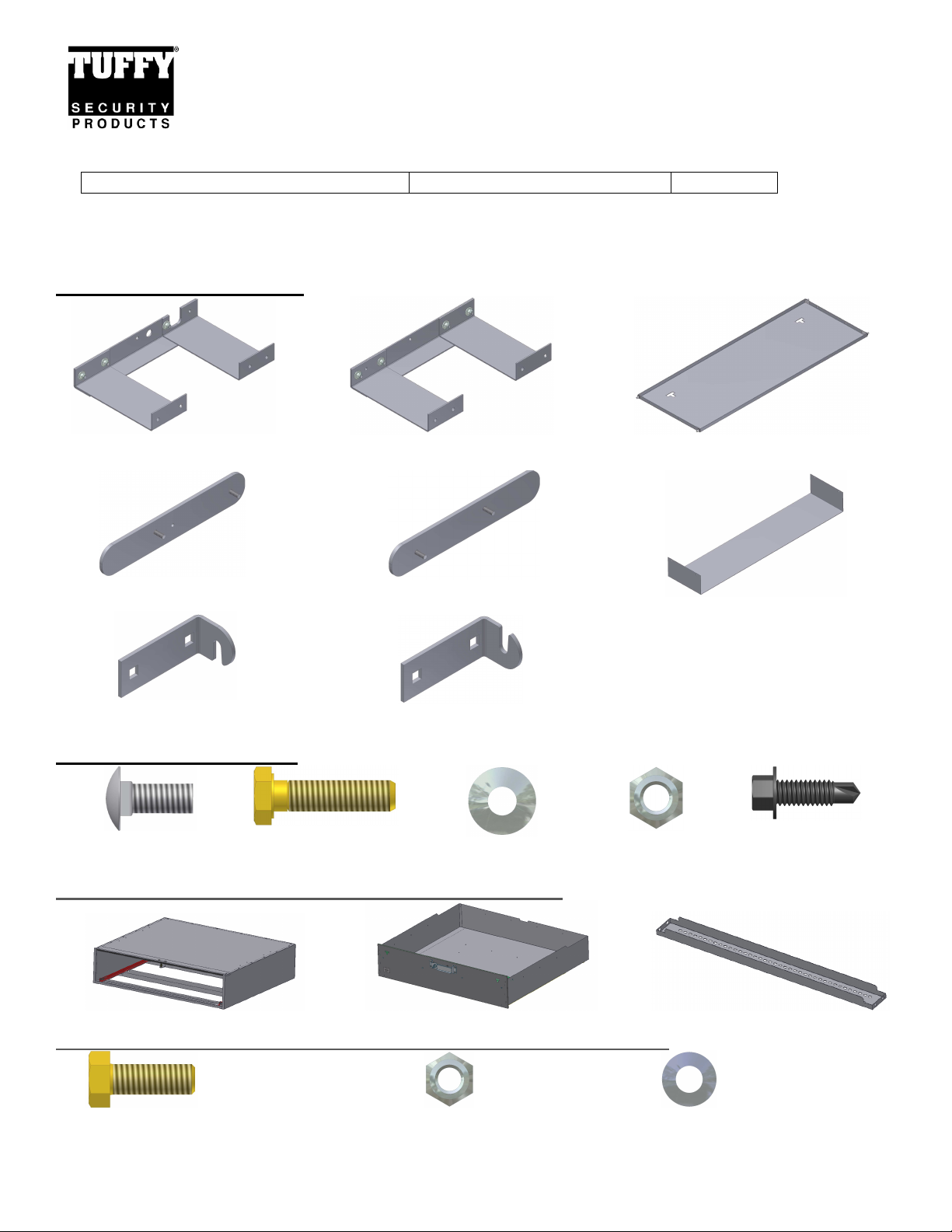
#304 Mounting Kit Parts
#16 (1) Lower Drivers Side
Assembly(Pre-assembled)
#2 (1) Upper Support Plate
Drivers Side
#11 (2) Tray Mount Bracket
Drivers Side
#17 (1) Lower Passenger Side
Assembly(Pre-assembled)
#1 (1) Upper Support Plate
Passenger Side
#10 (2) Tray Mount Bracket
Passenger Side
#304 Shipping Package
#12.1 (4) 5/16x3/4”
Carriage Bolts
#12.2 (8) 5/16x1” Bolts #12.3 (21) 5/16 Washers #12.4 (13) 5/16
Parts used which are included with the drawer assembly:
#8 (1) Electronics Tray
Nylock Nuts
#9 (1) Auxiliary Tray
(Optional)
#12.5 (4) 5/16”x1”
Self-Drilling Screw
Parts used from the drawer shipping package (Included with drawer):
#5.2.4 (4) 5/16-18x7/8” Bolts
Enclosure Drawer (1) Mounting Bracket
#5.2.2 (4) 5/16 Nuts
Page 1 of 7 – 10/17/2013
#5.2.3 (8) 5/16 Narrow OD Washers
Page 2
Tools required
• ½” Shallow socket with a long extension and a ratchet (Universal joint also helps)
• ½” Wrench
• 5/16” End Wrench/Socket
• 3/16” Drill Bit and Drill
• 3/8” End Wrench/Socket
Preparatory Mounting Directions
WARNING! This drawer/mount is rated to hold a maximum of 100# evenly distributed. This would include any
dividers mounted in the drawer. Never stand or sit on the Tuffy drawer or enclosure. The vehicle should not be
operated with the drawer opened and not secured shut. The drawer should not be operated/opened when not
level. Keep hands clear of moving parts and pinch points when maneuvering the drawer. Do not exceed the
rated weight capacity for this product.
THE DRAWER SHOULD ALWAYS BE EMPTY BEFORE REMOVING IT. CONSTANT SUPPORT MUST BE APPLIED
TO HOLD UP THE FRONT OF THE DRAWER THROUGHOUT THE ENTIRE REMOVAL PROCESS SO IT DOES NOT
CAUSE INJURY AND/OR DAMAGE.
1. Remove the rear seatback from the vehicle(see vehicle owners manual), as well as the headliner material above and
below the Package Tray (the area behind the rear seat and below the rear windshield) is accessible from both above
and below. The ¼” Upper Support Plates rest in pockets located in the top of the package tray, while the
corresponding Lower Assemblies are installed below the package tray “sandwiching” it to provide maximum strength
and weight distribution. When fully assembled, the mounting brackets suspend the drawer below the cooling fan and
speaker bottoms. It is designed to provide clearance for these items, while still allowing access to the spare tire and
the trunk floor.
2. The mounting bracket location measurements in these instructions are for the standard vehicles listed at the top of
Page 1. Due to the wide variety of options, models, and other variables your vehicle may be different. If the
dimensions in the vehicle where the drawer will be installed vary from those illustrated, the dimensions for the
mounting locations will need to be adjusted.
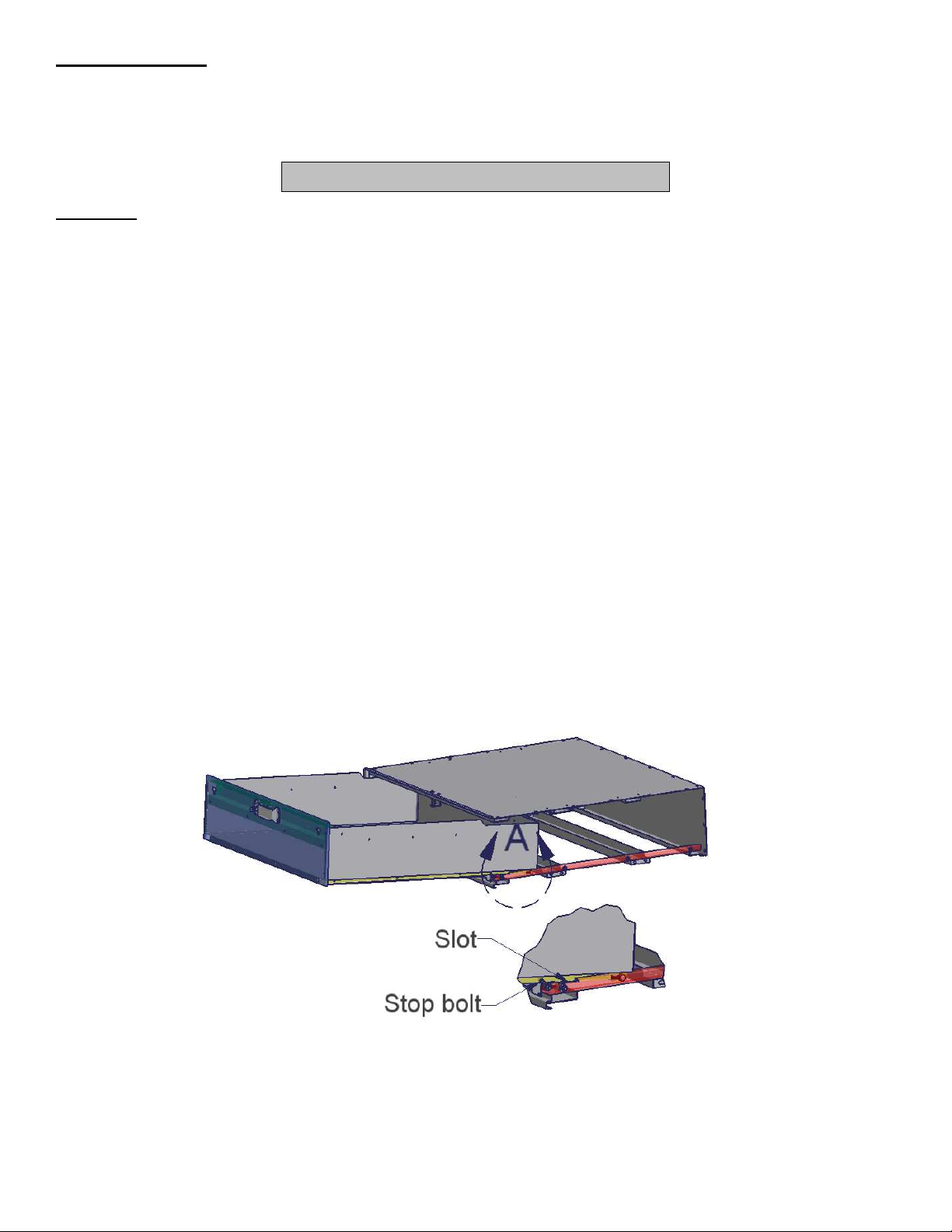
3. Remove the drawer from the enclosure. Pull the drawer out until it stops. Lift up the front of the drawer and pull it out
a few inches further until the stop bolts on the drawer slides clear the rollers on the enclosure slide. Pull the drawer
again until it stops, being sure to support the front of the drawer. Pivot the front of the drawer down and lift the rear
end of the drawer out so the rollers on the drawer slides pull free through the slots in the enclosure slides. Reverse
steps to install. (See Figure A)
FIGURE A
ATTENTION:
FREQUENT LUBRICATION IS NECESSARY ON THE LOCKING SYSTEM
The pushbutton lock contains an “O” ring seal to protect the interior from dust and water. If this mechanism is not
lubricated regularly it will become difficult to operate and it may not return to its home position preventing the key from
operating the lock. If this happens simply pull up on the pushbutton to manually bring it back to its home position.
Lubricate the pushbutton with a light lubricant such as silicone spray. The pushbutton may have to be periodically
disassembled and cleaned.
Call (970) 564-1762 for Technical Support
Page 2 of 7 – 10/17/2013
Page 3
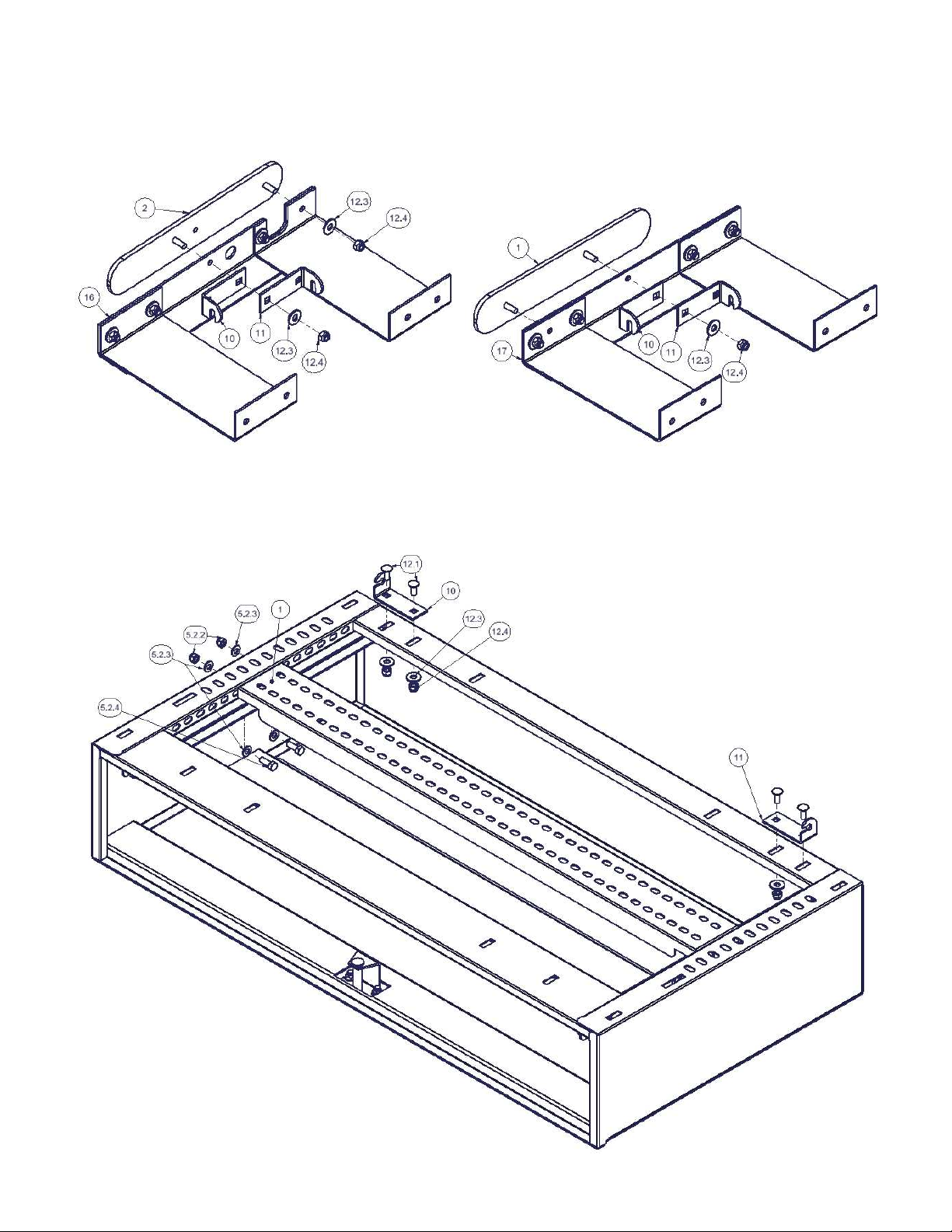
1. Begin the installation by partially disassembling the Drivers Side Assembly by removing 2) #12.3 Washers, and 2)
#12.4 Nylock Nuts(See Figure 1). This will allow the #2 Upper Support Plate, the #16 Lower Drivers Side Assembly,
1)#10 Tray Mount Bracket, and 1)#11 Tray Mount Brackets to be separated. Save the Nuts and Washers to be
used later in the installation. Note the relative orientation of the parts as this is their final configuration once
installed.
FIGURE 1 FIGURE 2
2. Partially disassemble the Passenger Side Assembly by removing 1) #12.3 Washer, and 1) #12.4 Nylock Nut(See
Figure 2). This will allow the #1 Upper Support Plate, the #17 Lower Passenger Side Assembly, 1) #10 Tray Mount
Bracket, and 1) #11 Tray Mount Bracket to be separated. Save the Nuts and Washers to be used later in the
installation. Note the relative orientation of the parts as this is their final configuration once installed.
FIGURE 3A
Page 3 of 7 – 10/17/2013
Page 4

FIGURE 3B
3. Invert the enclosure and install (1) #11, and (1) #10 Tray Mount Bracket using the hardware and positions
illustrated(See Figures 3A/3B). In addition, attach (1) mounting bracket to the drawer enclosure with the illustrated
hardware. The location of the mounting bracket is secondary and may be moved forward or back depending on
customer preference for mounting of other equipment(fire extinguisher, etc). These bolts are difficult to reach; Use a
½” shallow socket with a long extension and a ratchet (Universal joint also helps) and a ½” wrench on the other end.
Unbolting the slide using a 7/16” wrench will make things easier as well. The Mounting Bracket parts and
fasteners are included with the drawer.
4. Place the enclosure in the trunk with the back of the enclosure facing the front of the car, and the tray mount brackets
facing down. Due to the shape of the trunk opening the enclosure must be placed in the trunk at a downward angle
from above(the widest portion of the trunk), and rotating it through this portion of the opening. Rest the enclosure on
the floor of the trunk.
5. Moving to the area between the “Package Tray” and the Rear Window, remove the Grounding Lug that is located in
the Package Tray pocket on the Driver’s Side of the car, also loosen the bolt that holds the electrical connector near
the forward end of the pocket. Both of these fasteners have 5/16” heads. Place the #2 Upper Support plate into the
pocket, slipping it under the wiring that runs across the package tray with the studs facing down into the openings and
the open hole in the plate centered on the threaded hole for the grounding lug bolt. Do not reinstall/tighten these
stock fasteners until after the enclosure is in place.
6. On the Passenger’s Side a single bolt(5/16”) needs to be loosened near the front of the pocket to make room for the
#1 upper support plate. Place the plate in the pocket with the studs facing down.
7. Lift the #17 Lower Passenger’s Side Assembly into place on the studs of the #1 Upper Support Plate in the orientation
shown in Figure 2. Install (2) #12.3 washers, and (2) #12.4 Nylock Nuts(1 set from Step #1, 1 from Shipping
Package) on the studs but only tighten hand tight as enclosure installation requires the brackets to be spread apart.
8. Lift the #16 Lower Driver’s Side Assembly into place on the studs of the #2 Upper Support plate as shown in Figure 1,
and use (2) #12.3 washers, and (2) #12.4 Nylock nuts(saved from Step #2)hand tighten to hold assembly in place.
9. With help spread the brackets and lift the enclosure into place under the “Package Tray”. Once in place, allow the
brackets to capture the enclosure and support its weight.
10. After making sure the Upper Support Plates are resting in their respective pockets, tighten the (4) #12.4 Nylock
Nuts(Steps #7/8) to 15 ft-lbs. To make this step easier the enclosure may be slid to the rear of the car and supported
to give access to the nuts from the back seat area of the vehicle.
Page 4 of 7 – 10/17/2013
Page 5

11. Slide the enclosure back into the brackets and into final position with the back of the enclosure ¼” beyond the forward
surfaces of the brackets(See Figure 4).
FIGURE 4
12. Attach the enclosure to the brackets using (8) #12.2 Hex Bolts, (16) #12.3 Flat Washers, and (8) #12.4 Nylock Hex
Nuts. Leaving them loose for enclosure flexibility until all are in place, then tightening to approx. 15 ft-lb(See Figure 5)
FIGURE 5
Page 5 of 7 – 10/17/2013
Page 6

13. From the rear seat area of the vehicle, install the #8 Electronics Tray onto the Tray Mount Brackets attached to the
rear of the enclosure.(See Figure 6)
FIGURE 6
14. Place the remaining #10 and #11 Tray Mount Brackets at the lower end of the Electronics Tray, resting the tray on the
dimples in the Brackets, and making sure the rubber washers are within 1/16” of the Bracket. Mark lines on the
vehicle floor along the outside and the forward edges to correctly locate the Brackets in the next step(See Figure 7).
FIGURE 7
15. Remove the #8 Electronics Tray, realign the #10 and #11 Mount Brackets with the lines drawn in Step #14. Make a
mark at the center of each of the square holes in the Brackets. Remove the Brackets and drill (4) 3/16” diameter
holes through the sheet metal(making sure there is nothing directly below).
16. Permanently install the #10, and #11 Tray Mount Brackets using (4) #12.5 Self-Drilling Screws in the pre-drilled holes.
17. The electronics may now be installed onto the #8 Electronics Tray using appropriate hardware making sure that there
is enough slack in wires to allow the Electronics Tray to be moved to the rear section of the trunk for future
maintenance of electronic equipment. Refrain from using the upper 1” of the Electronics Tray as it may cause
interference when removing the Tray from the enclosure.
18. Loosen, but do not remove the (4) #12.4 Nylock Nuts that hold the Tray Mount Brackets to the enclosure, and slide
the brackets toward the rear of the enclosure(See Figure 8).
19. Place the Electronics Tray into the floor mounted Brackets, and lift/rotate the Tray into place pulling the Tray toward
the rear of the vehicle to insure contact with the lower Tray Mount Brackets(See Figure 8)
Page 6 of 7 – 10/17/2013
Page 7

20. Pull the upper Tray Mount Brackets toward the front of the enclosure and retighten the (4) Nuts loosened in Step 18
while maintaining pressure on the Brackets to prevent rattles(See Figure 8).
FIGURE 8
21. Reinstall/tighten the factory fasteners in the “Package Tray” that were loosened/removed in Steps 5/6. Reinstall
headliner onto the upper side of the “Package Tray”.
22. Replace rear seatback to factory location.
23. Install the drawer into the enclosure, using the procedure of Step 3 on Page 2 of these instructions in opposite order.
AUXILIARY TRAY INSTALLATION
1. Install the #9 Auxiliary Tray to the #8 Electronics Tray using (4) #13.3 10-32 x ½” Hexwasher Screws, (4) #13.2
10-32 Flat Washers, and (4) #13.1 10-32 Nylock Hexnut(All are included with Auxiliary Tray) through the prepunched holes.
Call (970) 564-1762 for Technical Support
Page 7 of 7 – 10/17/2013
 Loading...