

Page 1

OPERATION INSTRUCTIONS
QC CHECK
VISUAL INSPECTION
RUBBER SEAL
CORRECT KEY & COMBO CODES
PUSHBUTTON LOCK TEST
COMBO LOCK TEST
LATCH TEST
GAS SPRING TEST
FOAM FINISH KIT INSPECTION
UNLOCKED WITH KEY INSIDE
QC INSPECTOR INITIALS ____________
STEP 1.3
STEP 1.4
Tactical Security Lock-Box #301
Opening the Tuffy Security Lock-box
1. Using the pushbutton key lock:
Warning: keep clear of the lid when opening it. There is a gas strut which forces
the lid open.
1.1. Locate the key and unlock the pushbutton lock.
1.2. Press the pushbutton while at the same time pulling the lid open using the handle.
2. Using the pushbutton combination lock:
Warning: keep clear of the lid when opening it. There is a gas strut which forces the lid open.
Attention: The combination pushbutton lock is typically shipped from the factory with either no code entered
yet or “12345” and will need to be reset by the customer. Alternative pre-programmed code is
________________
2.1. Turn the OPEN lever clockwise to disengage the latch mechanism and pull the lid open while holding the OPEN
lever clockwise. Releasing the lever before pulling the lid open will allow the latch to re-engage preventing the lid
from opening.
Instructions for securing the Tuffy Lock-box to the vehicle
1.1. Open the lid.
1.2. Secure one end of the cable to an adequate anchor point in the vehicle, by creating a loop in the cable(See
Figure 2).
1.3. Place the other cable end into the notch in the cable anchor(located just behind the hinge on the left side of the
box. (See Figure 1)
1.4. Lift the cable loop so that the pinched end of the cable loop slips over the front side of the cable anchor.
(See Figure 1)
1.5. Route the cable through the notch in the side of the box(See Figure 2), and close the lid.
Figure 1(RIGHT SIDE PANEL REMOVED FOR CLARITY)
Page 1 of 5 – Rev 9/19/2012
Page 2
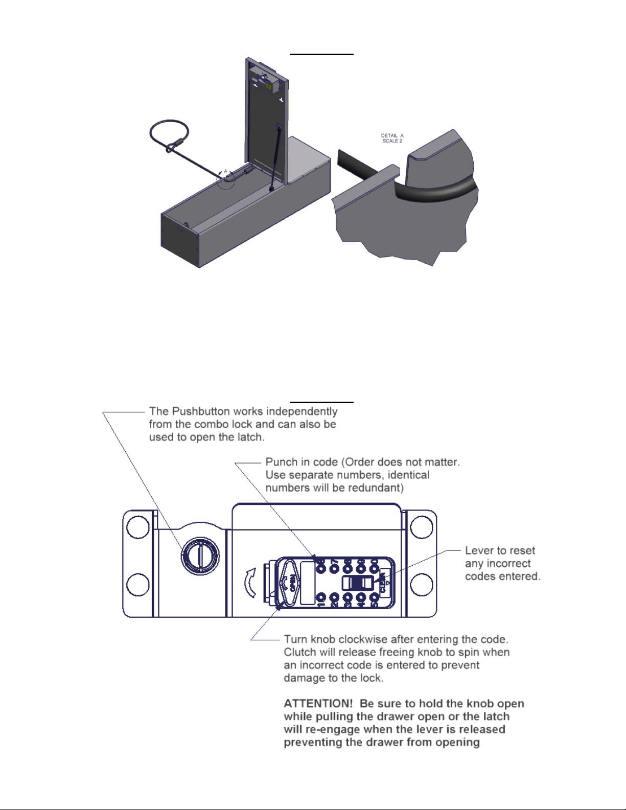
Figure 2
Instructions for changing the combination
Attention: The combination pushbutton lock is typically shipped from the factory with either no code entered yet
or “12345” and will need to be reset by the customer. Alternative pre-programmed code is ________________
2. Selecting your combination
2.1. Please look at the front of the combination lock. There are buttons numbered 1 through 0. There is also an
OPEN lever and a CLEAR button. (See Figure 3)
2.2. Select your own combination and keep the combination in a safe place.
2.3. For best results, select between four and seven numbers in your combination. Each number can only be used
one time. Do not use number combinations that can be easily guessed.
Figure 3
Page 2 of 5 – Rev 9/19/2012
Page 3

3. Setting your combination
WARNING: Improperly setting the combination is not covered under the warranty. Do not disassemble the
lock. Doing so voids the warranty.
3.1. Press on the CLEAR to reset the combination lock. (See Figure 3)
3.2. It is not necessary to remove the latch cover on the back of the latch mechanism. A window has been provided in
the face of the latch cover to allow for easy changing of the combination code. Simply open the lid and locate the
latch cover combination window.
3.3. Looking at the rear of the pushbutton combination lock from the inside of the box you will see ten numbered
buttons with arrows. (These are actually upside down the way the latch is installed) These numbers correspond
to the numbered button on the front of the lock. (See Figure 4)
3.4. The arrows on the screws are pointing in the direction which the previous codes were set to. (See Figure 4)
IMPORTANT: Open knob must be in LOCKED position before the code can be changed.
3.5. Use a small screwdriver to rotate the arrows. For each number in your combination, apply light pressure and
rotate a half turn so that the arrow points correctly (SET ON) and snaps up. Be sure to reset all the arrows to
SET OFF before entering the new combination. (See Figure 4)
3.6. Check to make sure that the arrow of any number that is not in the combination is pointing the correct direction
(SET OFF). (See Figure 4)
CAUTION: Arrows must point either direction (SET ON or SET OFF). An arrow pointing differently indicates
that it has not snapped up, the combination will not work. Test the combination before locking the lid.
Figure 4
4. Testing your combination before closing the lid.
Please note: This product is equipped with a clutch mechanism to protect it from forced entry. Do not be
alarmed if the OPEN lever turns even if the correct combination has not been entered.
4.1. Do not close the door. Press on the latch mechanism on the inside of the box to engage the latch.
4.2. Make sure OPEN lever is in home position. If not, turn OPEN lever counterclockwise until it’s in the home
position. On the front of the lock, push only the numbered buttons in your combination. If a mistake is made,
shift the CLEAR lever and re-enter the combination. (See Figure 3)
4.3. Turn the OPEN lever clockwise to disengage the latch mechanism. When the latch mechanism disengages it will
spring back open again. If you have entered an incorrect combination, you can return the buttons to their original
setting by shifting the CLEAR lever. (See Figure 3)
4.4. When you turn the lever, the combination will clear. (See Figure 3)
4.5. To relock the combination lock turn the OPEN lever counter-clockwise. (See Figure 3)
5. Test the combination lock by closing, unlocking and reopening the lid.
ATTENTION: The OPEN lever must be turned clockwise and held in position while at the same time the lid is
pulled open.
5.1. Close the lid until the latch engages.
5.2. Make sure OPEN lever is in home position. If not, turn OPEN lever counterclockwise until it’s in the home
position. On the front of the lock, push only the numbered buttons in your combination. If a mistake is made,
shift the CLEAR lever and re-enter the combination. (See Figure 3)
Page 3 of 5 – Rev 9/19/2012
Page 4

5.3. Turn the OPEN lever clockwise to disengage the latch mechanism and pull the lid open while holding the OPEN
lever clockwise. Releasing the lever before pulling the lid open will allow the latch to re-engage preventing the lid
from opening. (See Figure 3)
6. GAS STRUT REPLACEMENT OR REVERSAL:
**Attention: The gas strut is considered a “wear” item and may need to be replaced after a period of time.
On some models, the Lock-box is shipped from the factory with the gas strut located on the left hand side.
On these models, the gas strut may be reversed to the opposite side if desired.
6.1 To replace or reverse the gas strut, start by removing the spring clip from the top and bottom mounting heads by
prying the clip up with a flat screwdriver.
6.2 Remove the gas strut from the ball studs located at the top and bottom of the strut.
**Note the orientation of the factory installed gas strut is with the gas strut body located at the top.
6.3 If reversing the strut location, remove the (2) ball studs from the mounting flanges on the Lock-box body and
relocate to the opposite side.
6.4 Install a new or re-install the gas strut onto the ball studs and re-install the retaining spring clips.
7 Required Periodic maintenance: Failure to perform periodic maintenance can result in the loss of access
inside the security enclosure and failure of components.
7.1 Lubrication is required for all moving parts. The schedule will vary depending on the level of usage and
environmental conditions. Once a month is a good starting point. Be sure to lubricate all friction points
completely. Use high temperature lithium grease. Key lubrication points are shown in the illustration
below. (See figure 5)
7.2 If the latch handle is removed or has been bumped out of alignment it will need to be adjusted correctly
again. The gap shown between the knob and the stop is critical and can vary slightly. If the gap is too
small the knob cannot be turned enough to unlock the latch. If the gap is too large then the knob can be
turned past its stop point which trips the internal clutch and will not unlock the latch. Adjust the handle
so the gap is the largest possible initially then if the clutch is tripped move it in small increments until it
unlatches correctly. (See figure 6)
7.3 All fasteners should be checked to ensure they are not loose. The schedule will vary depending on the
level of usage, environmental conditions and typical vibration encountered. Once a month is a good
starting point. Loctite may need to be reapplied after extended periods of time.
Page 4 of 5 – Rev 9/19/2012
Page 5

Figure 5
Figure 6
Call (970)564-1762 for Technical Support
Page 5 of 5 – Rev 9/19/2012
 Loading...