

Page 1
INSTALLATION INSTRUCTIONS
#280 Combo Lock Kit for #167, #171, or #258
(This kit is designed to install on a rear cargo/tactical drawer sold separately.
Rear cargo drawer must be pre-manufactured to accept this kit.)
Attention: For instructions on setting the combination, search “089 - COMBINATION LOCK FOR CAMLOCK
SYSTEM” at tuffyproducts.com and click on the link to the pdf “Operating instructions - setting the combination”
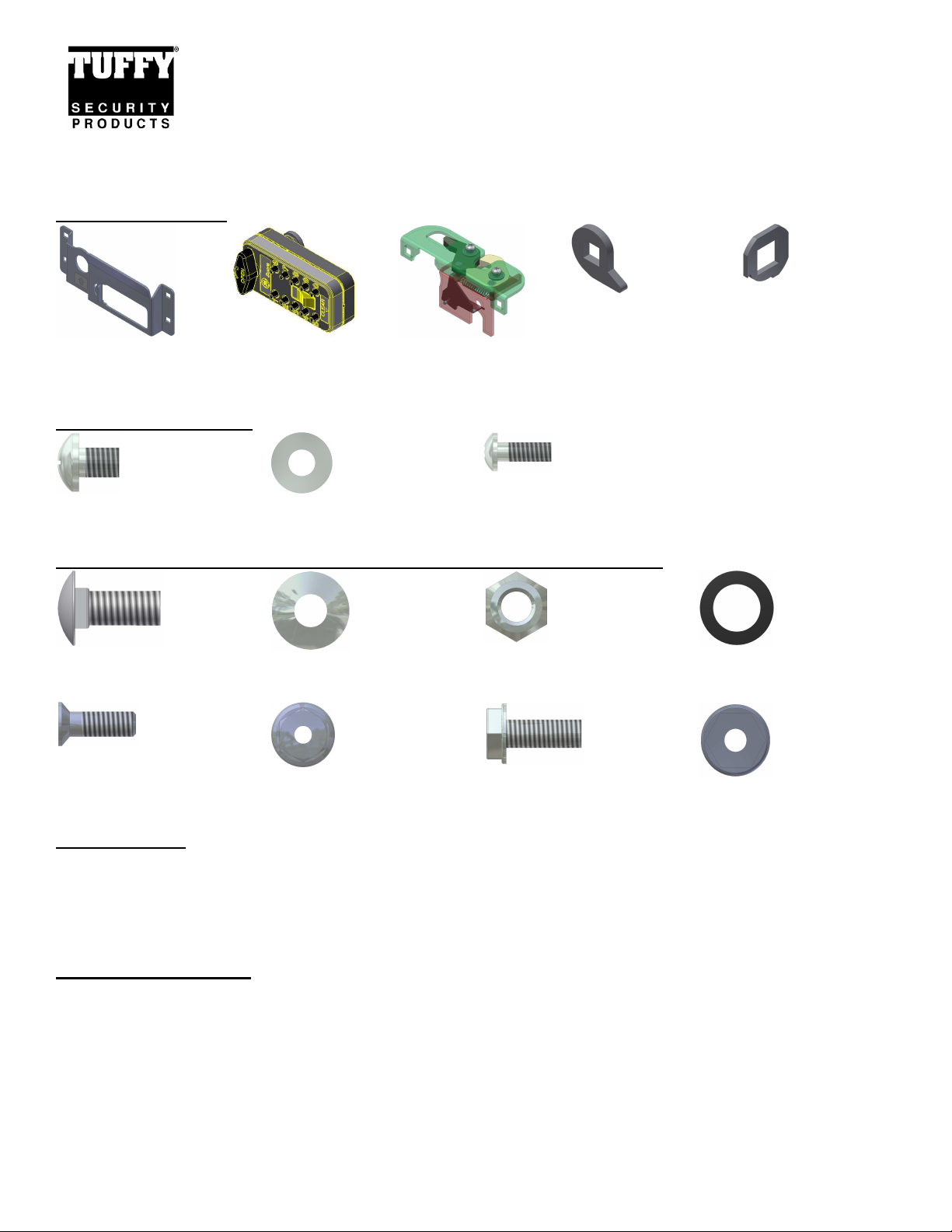
280 Parts Checklist
#20.4.7 (1) Combo
Lock Drawer Handle
280 Shipping Package
#20.4.15 (1) #10-24 x ¼”
Cam screw
Parts used from the drawer shipping package (Included with drawer)
#20.3.2 (6) 5/16-18x7/8”
Carriage Bolts
#20.4.6 (1) 089
Combination Lock
Assembly
#20.4.16 (1) #10 washer #20.4.14 (4) #6-32 x 5/16”
#20.3.3 (6) 5/16 Washers
#20.4.5 (1) Combo
Latch Assembly
Torx screw
#20.3.4 (6) 5/16 Nuts
#20.4.10 (1) Combo
Cam
#20.4.9 (1) Combo
Stop Washer
#20.3.6 (2) 5/16” Rubber
Washers
#17.3 (4) #10-32 Flange
nuts
#17.1 (2) #8-32 x 1/2”
Philips flat head screws
#17.2 (2) #8-32 Nuts #17.4 (4) #10-32 x ½” Hex
washer screw
Tools required
• ½” socket and a ratchet
• ½” Wrench
• 5/16” socket and ratchet or 5/16” wrench
• Philips or Flat screwdriver
• T-15 Torx bit or screwdriver
Installation Directions
REMOVAL OF THE DRAWER FROM THE ENCLOSURE IS NOT REQUIRED TO PERFORM THIS INSTALLATION. IF
THE DRAWER IS TO BE REMOVED, FOR SAFETY THE DRAWER REMOVAL REQUIRES AT LEAST (2) PEOPLE.
THE DRAWER SHOULD ALWAYS BE EMPTY BEFORE REMOVING IT. CONSTANT SUPPORT MUST BE APPLIED
TO HOLD UP THE FRONT OF THE DRAWER THROUGHOUT THE ENTIRE REMOVAL PROCESS SO IT DOES NOT
CAUSE INJURY AND/OR DAMAGE.
Page 1 of 5 – 06/23/2011 – Rev6/23/2011
Page 2
BEFORE BEGINNING THIS INSTALLATION, VERIFY THAT YOUR REAR CARGO OR TACTICAL GEAR DRAWER
HAS BEEN PRE-MANUFACTURED TO ACCEPT THIS COMBO LOCK KIT. THE DRAWER FRONT MUST FEATURE
HOLES FOR THE COMBO LOCK. A COMBO HOLE COVER PLATE MAY BE COVERING THE COMBO LOCK
HOLES. REFER TO FIGURE 1 AND FIGURE 4.
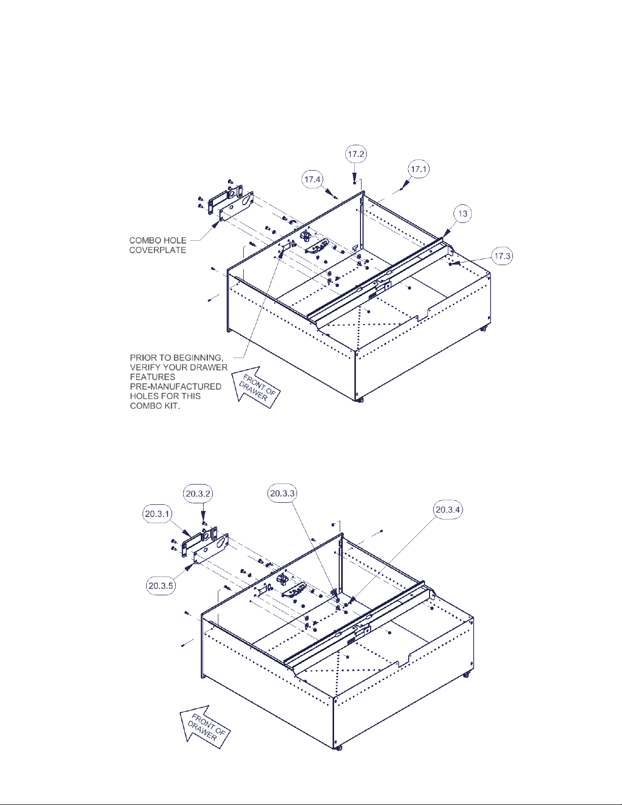
1. Remove the #13 Drawer Front Latch Cover by removing the (2) #17.1 screws and (2) #17.2 nuts on each side
followed by the (4) #17.4 screws and (4) #17.3 nuts at the drawer front. Save all hardware and latch cover for reuse.
(Figure 1)
FIGURE 1
2. Remove the #20.3.1 Standard Drawer handle and #20.3.5 Combo Hole Cover Plate by removing the (4) #20.3.2
carriage bolts, (4) #20.3.3 washers, and (4) #20.3.4 nuts. Save all hardware for reuse. (Figure 2)
FIGURE 2
Page 2 of 5 – 06/23/2011 – Rev6/23/2011
Page 3

3. Remove the #20.2.3 Standard Latch assembly by removing the (2) 20.3.2 carriage bolts, (2) 20.3.6 rubber washers,
(2) #20.3.3 washers, and (2) #20.3.4 nuts. Save all hardware for reuse. (Figure 3)
FIGURE 3
4. Install the #20.4.6 Combination Lock Assembly through the pre-manufactured holes in the #9 Drawer Front. Fasten
the combo lock to the drawer front with the (4) #20.4.14 screws. Install the #20.4.9 Stop Washer and the #20.4.10
Combo Cam onto the combination lock assembly shaft. Fasten with the (1) #20.4.16 washer and (1) #20.4.15 screw.
(Figure 4)
**NOTE THE POSITION AND ORIENTATION OF THE STOP WASHER AND COMBO CAM IN FIGURE 4. BOTH
MUST BE INSTALLED CORRECTLY ONTO THE SHAFT IN ORDER FOR THE COMBINATION TO FUNCTION
PROPERLY.
FIGURE 4
Page 3 of 5 – 06/23/2011 – Rev6/23/2011
Page 4

5. Install the #20.4.5 Combo Latch Assembly onto the drawer front panel by fitting it over the pushbutton and combo
locks. **This is performed on the inside face of the drawer. Fasten the assembly to the drawer front with the (2)
#20.3.2 carriage bolts, (2) #20.3.6 rubber washer, (2) #20.3.3 washers, and (2) #20.3.4 nuts (removed in Step 3).
(Figure 5)
FIGURE 5
6. Install the #20.4.7 Combo Lock Drawer Handle to the front of the drawer and install with the (4) #20.3.2 carriage bolts,
(4) #20.3.3 washers, and (4) #20.3.4 nuts (removed in Step 2). (Figure 6) **NOTE THE ORIENTATION OF THE
HANDLE FITS OVER THE COMBO LOCK AND ORIGINAL PUSHBUTTON LOCK IN ONLY ONE WAY.
FIGURE 6
Page 4 of 5 – 06/23/2011 – Rev6/23/2011
Page 5

7. It is most convenient to set the combination lock code at this time. Refer to the document titled “089 Operating
instructions” for instructions on setting combination code. The combination pushbutton lock is typically shipped
from the factory with either no code entered yet or “12345” and will need to be reset by the customer.
**DO NOT CLOSE THE DRAWER AT THIS TIME. Test the operation and function of the combination lock and the
original pushbutton lock before closing the drawer.
8. Test the combination lock and the original pushbutton lock by closing, unlocking and reopening the drawer. Refer to
the document titled “089 Operating instructions” for instructions on operating the combination lock.
9. Finally, re-install the #13 Drawer Front Latch Cover into position and fasten with the (2) #17.1 screws and (2) #17.2
nuts on each side followed by the (4) #17.4 screws and (4) #17.3 nuts at the drawer front. (Figure 7)
FIGURE 7
ATTENTION:
FREQUENT LUBRICATION IS NECESSARY ON THE LOCKING SYSTEM
The pushbutton lock contains an “O” ring seal to protect the interior from dust and water. If this mechanism is not
lubricated regularly it will become difficult to operate and it may not return to its home position preventing the key from
operating the lock. If this happens simply pull up on the pushbutton to manually bring it back to its home position.
Lubricate the pushbutton with a light lubricant such as silicone spray. The pushbutton may have to be periodically
disassembled and cleaned.
Call (970) 564-1762 for Technical Support
Page 5 of 5 – 06/23/2011 – Rev6/23/2011
 Loading...