

Page 1
INSTALLATION INSTRUCTIONS
Please read and fill out the enclosed warranty registration card to activate your warranty.
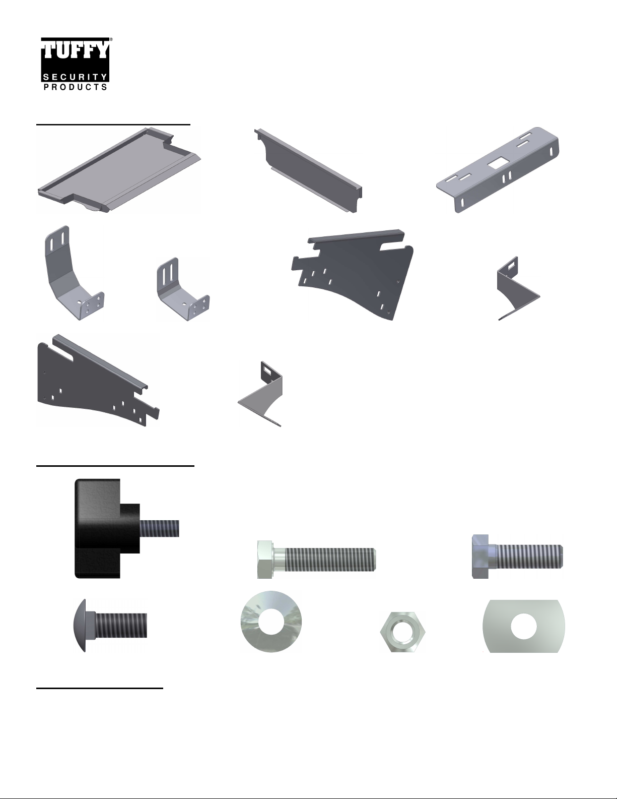
SHIPMENT CONTENTS
DECK ENCLOSURE #275
#1 Lid #4 Front Panel #9 Top Mount
#10 Large Bracket #11 Small Bracket #5 Left Mounting Panel #7 Left Filler Bracket
#6 Right Mounting Panel #8 Right Filler Bracket
HARDWARE PACKAGE
#15.1 (4) ½-20 X ½” Knob Screw #15.26 (4) 8MM x 35mm Bolt #15.25 (10) 5/16 x 1” Bolt
#15.19 (12) 5/16 x ¾” Carriage Bolt #15.18 (36) 5/16 Washer #15.21 (22) 5/16 Locknuts #15.24 (4) 8mm Rec nuts
TOOLS REQUIRED
• ½” Socket, ratchet & wrench
• T-40 Torx (For vehicles with an existing hardtop)
• 13mm Socket (For vehicles without an existing hardtop)
• Optional Security step – Drill and 3/8” bit
Page 1 of 6 – 1/28/2011 – Rev12/13/2011
Page 2
ATTENTION:
• THIS ENCLOSURE WAS DESIGNED FOR A STOCK OEM VEHICLE, ANY MODIFICATIONS MADE
MAY AFFECT THE FIT INCLUDING: CARPET REMOVAL/CHANGES, SEATS, ETC.
• On Jeep Wrangler JK vehicles with Manual Door Locks only, the rear tailgate lock must be locked
manually with key in order for Tuffy enclosure security to function. Vehicles with Power Door
Locks by default also feature Remote Keyless Entry and the Vehicle Security Alarm. Arming of the
Vehicle Security Alarm (by locking the doors with either the key fob or interior power door lock
switch) automatically disables the interior power door lock switches and ensures the tailgate and
Tuffy enclosure are secure, even on softtop models or with the top removed. There is a 16-second
alarm arming period during which the interior power door lock switches remain active.
•
For safety do not place any items on top of the enclosure that are not adequately secured to the
vehicle to prevent movement in the event of an accident or abrupt speed changes.
INSTALLATION:
PLEASE READ ALL SAFETY WARNINGS AND INSTRUCTIONS THOROUGHLY BEFORE STARTING INSTALL
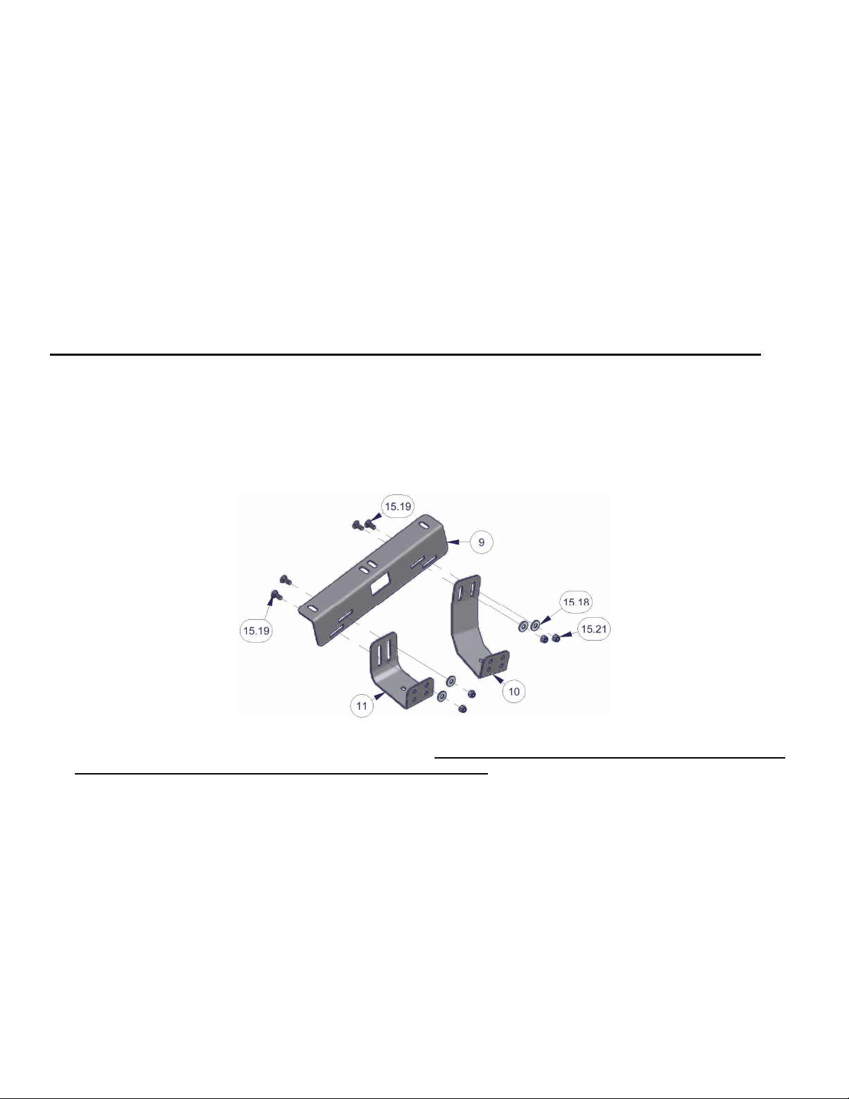
• Assemble the left/drivers side mounting assembly. Do not fully tighten the hardware, leave them loose enough for
adjustment.
• Fasten #9 Top Mount to the #10 Large and #11 Small brackets using (4) #15.19 Carriage bolts, (4) #15.18 Washers
and (4) #15.21 nuts as illustrated. Leave hardware slightly loose. (See Figure 1)
Figure 1
• Fasten #5 Left Mounting Panel to the left/drivers side assembly using (4) #15.25 Bolts, (8) #15.18 Washers and (4)
#15.21 nuts as illustrated. Leave hardware slightly loose. Important! The left and right panel look similar but the “U”
shaped bend is opposite and should face the outside of the vehicle. (See Figure 2)
• Fasten #7 Left Filler Panel to #5 Left Mounting Panel using (2) #15.19 Carriage bolts, (2) #15.18 Washers and (2)
#15.21 nuts as illustrated. Leave hardware slightly loose. (See Figure 2)
• Assemble the right/passenger side mounting assembly with the same hardware but mirrored/opposite of the left side.
Do not fully tighten the hardware, leave them loose enough for adjustment.
(Left/drivers side assembly)
Page 2 of 6 – 1/28/2011 – Rev12/13/2011
Page 3

Figure 2
• Fasten the left/driver and right/passenger mounting assemblies to the vehicle by following the applicable vehicle
specific instructions below. While tightening the hardware make sure the #9 bracket is adjusted toward the outside of
the vehicle as much as possible.
(Left/drivers side assembly)
• 4-door with an existing hardtop - If the vehicle has a hard top remove the (2) factory OEM torx bolts then refasten
the #9 top mounting brackets on top of the flange on the hardtop to the existing (2) holes using the original OEM
hardware as illustrated. (The 8mm x 35mm bolts included and 5/16” washers can be substituted if desired) (See
Figure 3)
• 4-door without an existing hardtop - Fasten the #9 top mounting brackets to the flange on the top of the vehicle
body through the existing holes using #15.26 Bolts, #15.18 Washers and #15.24 Nuts as illustrated. (See Figure
3)
• 2-door with an existing hardtop - If the vehicle has a hard top remove the factory OEM torx bolt then refasten the
#9 top mounting brackets on top of the flange on the hardtop to the existing hole using the original OEM bolt
through the indicated hole on #9 top mounting bracket. (The 8mm x 35mm bolts included and 5/16” washers can
be substituted if desired) (See Figure 3)
• 2-door without an existing hardtop - Fasten the #9 top mounting brackets through the hole illustrated to the flange
on the top of the vehicle body using #15.26 Bolts, #15.18 Washers and #15.24 Nuts as illustrated. (See Figure 3)
• Fasten the #4 Front Panel to the mounting assemblies using the (4) #15.1 Knob Screws. (See Figure 3)
• With the fasteners on the left & right mounting assemblies still slightly loose adjust all the component brackets and
mounting panels so that they are flush with the vehicle tub. Also adjust the mounting panels so the tab toward the
rear of the panel has about a ¾” gap between it and the plastic seat belt cover at the base of the sport bar as
illustrated. This gap size varies, ¾” is typical, but adjustment may be necessary upon final fit check. Then tighten all
hardware on both the left and right mounting assemblies. (See Figure 3)
Page 3 of 6 – 1/28/2011 – Rev12/13/2011
Page 4

Figure 3
• Install the #1 Lid by maneuvering it above the left and right mounting assemblies in the vehicle. Then pull the #1 lid
toward the rear of the vehicle until it stops while guiding the welded studs #13 into the slots in the #5 Left and #6 Right
Mounting Panels. Initially this will be tight but will loosen up after a break in period. Drop the lid closed then push the
#1 lid toward the front of the vehicle until it stops while guiding the welded studs #12 into the slots. (See Figure 4)
• Inspect that the #12 welded studs are bottomed out with the #1 Lid as far forward as it can go. Close/secure the rear
window then close the rear tailgate. If the tailgate is difficult to fully close or there is a gap between the tailgate and
the #1 lid loosen the fasteners on the left and right mounting bracket assemblies and adjust them as required then
refasten them and recheck. (See Figure 1, 2 & 4)
Page 4 of 6 – 1/28/2011 – Rev12/13/2011
Page 5

Figure 4
Page 5 of 6 – 1/28/2011 – Rev12/13/2011
Page 6

OPTIONAL SECURITY FASTENER STEPS
• After all adjustments and checks have been made the optional security fasteners can be added if desired. Remove
both the OEM inside wheel liners under the tub.
WARNING! - Make sure that there is nothing under the vehicle that will be damaged by the drill bit when drilling. The
exhaust is located in that area, be cautious not to touch it when hot.
• Mark the tub under the center hole in the #10 Large bracket (or #11 Small bracket if desired) on both wheel wells and
drill a 3/8” hole in each. It is recommended to use silicone sealant on any drilled holes to prevent rusting. (See Figure
5)
• Secure brackets to the vehicle using #15.25 bolts, #15.18 Washers and #15.21 nuts through each hole drilled. (See
Figure 5)
• Reattach OEM inside wheel liners under tub.
Figure 5
2-DOOR REAR SEAT STORAGE INSTRUCTIONS
The rear seat can be stored, folded and tumbled in 2-door models, with the deck enclosure installed, with some limitations
and adjustments.
LIMITATIONS: With the rear seat tipped forward the front seats will only recline to approximately 17 degrees when they
are positioned in the extreme rear setting. (This may end up too upright for tall people)
INSTRUCTIONS: Fold and tumble the rear seat. Unlatch the rear seat from both connection points on the left and right
side. Then re-latch the rear seat to only the front connection points on the left and right side. This tips the seat forward
enough to clear the deck enclosure when installed. The headrests can also be removed if more room is necessary but
this is typically not required.
IMPORTANT! Don’t forget to re-latch the rear seat to both connection points when use is desired again.
Call (970) 564-1762 for Technical Support
Page 6 of 6 – 1/28/2011 – Rev12/13/2011
 Loading...