

Page 1
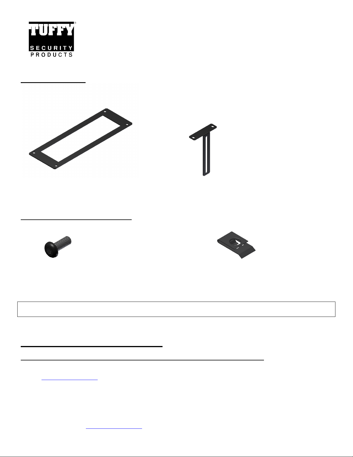
PARTS CHECKLIST
Command Center Modular Console Line
ITEM # - 195-______-__-___ Face Plates
See TuffyProducts.com for all console applications and related products
Please read and fill out the enclosed warranty registration card to activate your warranty.
#1 - (1) 195-______-__-___ FACEPLATE #2 - (2) 195-__-____ RADIO MOUNTING BRACKETS
(Note: Your face plate may differ from the one shown
above depending on your radio style.)
SHIPPING PACKAGE CHECKLIST
#3 - (4) 10-32X1/2 HEX HEAD SCREW #4 - (4) 10-32 U-NUTS
TOOLS NEEDED
• 3mm hex key or 3mm bit and cordless driver with clutch
ASSEMBLY INSTRUCTIONS:
PLEASE READ ALL INSTRUCTIONS THOROUGHLY BEFORE STARTING INSTALLATION.
1. The 195 Faceplate kits require a Tuffy Security Products Communications Console to mount to. Please see
www.tuffyproducts.com for the complete Command Center Console line.
2. IMPORTANT! Make sure the vehicle is parked on a flat surface, placed in park, and the emergency brake is activated.
Tuffy Security Products, www.tuffyproducts.com, (970) 564-1762 Page 1 of 2 - 12/01/2009
Page 2
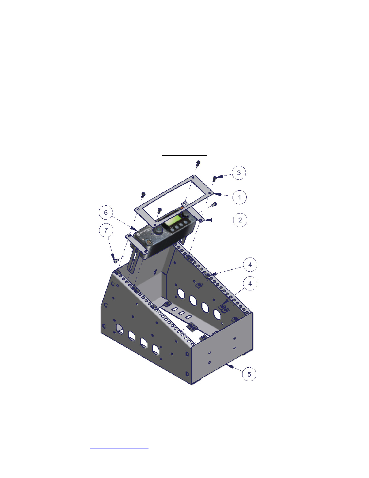
3. Install the snap fit U-Nuts (#4) in the appropriate locations so that they line up at each corner of the faceplate as shown in
Figure 1.
4. Install the Radio Mounting Brackets (#2) onto the side of the radio head (#6) using the hardware provided by the radio
manufacturer (#7). Note: The Radio Mounting Brackets (#2) are designed to be able to be bent by the installer if the radio
mounting locations are narrower than the radio head at the faceplate cutout.
5. Set the radio (#6) and mounting bracket (#2) assembly into the Tuffy console and check the fit. Note: Radio mounting
brackets can be cut to length if they interfere with any additional equipment that may be mounted in the console.
6. Place the faceplate over the radio and mounting bracket assembly, then install the four cap screws (#3) through the faceplate
(#1), then through the mounting brackets (#2) and into the U-Nuts (#4). Hand tighten cap screws until firmly tight but be
careful not to over tighten.
Note: Some faceplates do not have a cutout, such as in the case of a controller that mounts directly to the surface of the plate. In
this case, the #2 mounting brackets are replaced with small spacers to ensure that all of the faceplates are mounted flush.
FIGURE 1
NOTE: Many Radio Mounting Kits come with a part #199 Microphone Mounting Bracket kit, also sold separately; please see
included instructions for Mic Bracket installation.
Call (970) 564-1762 for Technical Support
Tuffy Security Products, www.tuffyproducts.com, (970) 564-1762 Page 2 of 2 - 12/01/2009
 Loading...