

Page 1
INSTALLATION INSTRUCTIONS
DECK ENCLOSURE #173
Please read and fill out the enclosed warranty registration card to activate your warranty.
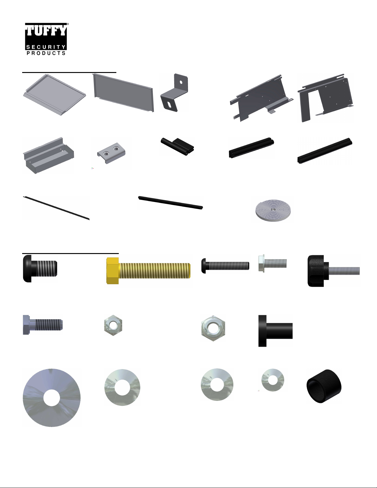
SHIPMENT CONTENTS
#3 Lid #4 Rear #5 Bracket #9 Left side #8 Right side
#7 (2) Trays #11 (2) Clamps #10.21 (2) 2 ¼” Seal #10.20 (2) 4 1/8” Seal #10.19 (2) 5 7/16”
#10.15 Seal 38 7/8” (Pre-installed) #10.14 Edge seal 38 1/8”
(Pre-installed)
#10.22 Rubber seal
Seal
HARDWARE PACKAGE
#10.12 (4) 3/8 x 5/8” Bolts
(2) PRE-INSTALLED ON
PROTECTIVE LID BRACE
#10.16 (4) 3/8 x 1 ¾” Bolts #10.7 (3) 10-32x1”
Screw
#10.10 (4) 1032x1/2” Screw
#10.11 (4) ¼-20x1”
Knob Screw
#10.30 (2) ¼”-20x3/4” Bolts #10.9 (4) 10-32 Nut #10.31 (2) ¼”-20
#10.13 (4) 3/8” Fender
Washers
Nuts
#10.17 (8) 3/8” Washers #10.32 (4) ¼”
Washers
Page 1 of 8 – 12/20/06 – Rev 11/4/13
#10.6 (3) 10-32 Rubber
Well Nut
#10.8 (7) #10
Washer
#10.18 (4) Rubber
spacer
Page 2
TOOLS REQUIRED
• All applications: Ratchet, 10MM Socket, 5/16” socket or wrench, 3/8” socket or wrench, 7/16” socket and wrench,
1/8” Allen wrench, 7/32” Allen wrench and a utility knife.
• Vehicles with subwoofer: 15MM Socket
• 4 door model - 18 MM Socket or wrench, 2 door model - 9/16” Socket
ATTENTION:
• THIS ENCLOSURE WAS DESIGNED FOR A STOCK OEM VEHICLE, ANY MODIFICATIONS MADE
MAY AFFECT THE FIT INCLUDING: CARPET REMOVAL/CHANGES, SEATS, ETC.
•
On Jeep Wrangler JK vehicles with Manual Door Locks only, the rear tailgate lock must be locked
manually with key in order for Tuffy enclosure security to function. Vehicles with Power Door
Locks by default also feature Remote Keyless Entry and the Vehicle Security Alarm. Arming of the
Vehicle Security Alarm (by locking the doors with either the key fob or interior power door lock
switch) automatically disables the interior power door lock switches and ensures the tailgate and
Tuffy enclosure are secure, even on softtop models or with the top removed. There is a 16-second
alarm arming period during which the interior power door lock switches remain active.
•
For safety do not place any items on top of the enclosure that are not adequately secured to the
vehicle to prevent movement in the event of an accident or abrupt speed changes.
INSTALLATION:
PLEASE READ ALL SAFETY WARNINGS AND INSTRUCTIONS THOROUGHLY BEFORE STARTING INSTALL
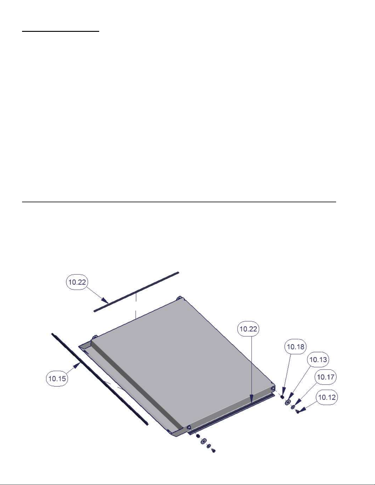
1. Remove the bolted-on protective metal brace from the front edge of the lid.
2. Install the lid hardware on all (4) welded studs by sliding #10.18 rubber spacers on first then #10.13 fender washer,
10.17 washer and #10.12 Bolt. (2) #10.12 Bolts were removed in Step #1 and are reused here. (See Figure 1)
3. Cut and install the #10.22 rubber seal on #3 Lid in the center of the flange as illustrated. (Trim seal #10.15 on the
front edge of the lid is installed at the factory). (See Figure 1)
Figure 1
Page 2 of 8 – 12/20/06 – Rev 11/4/13
Page 3
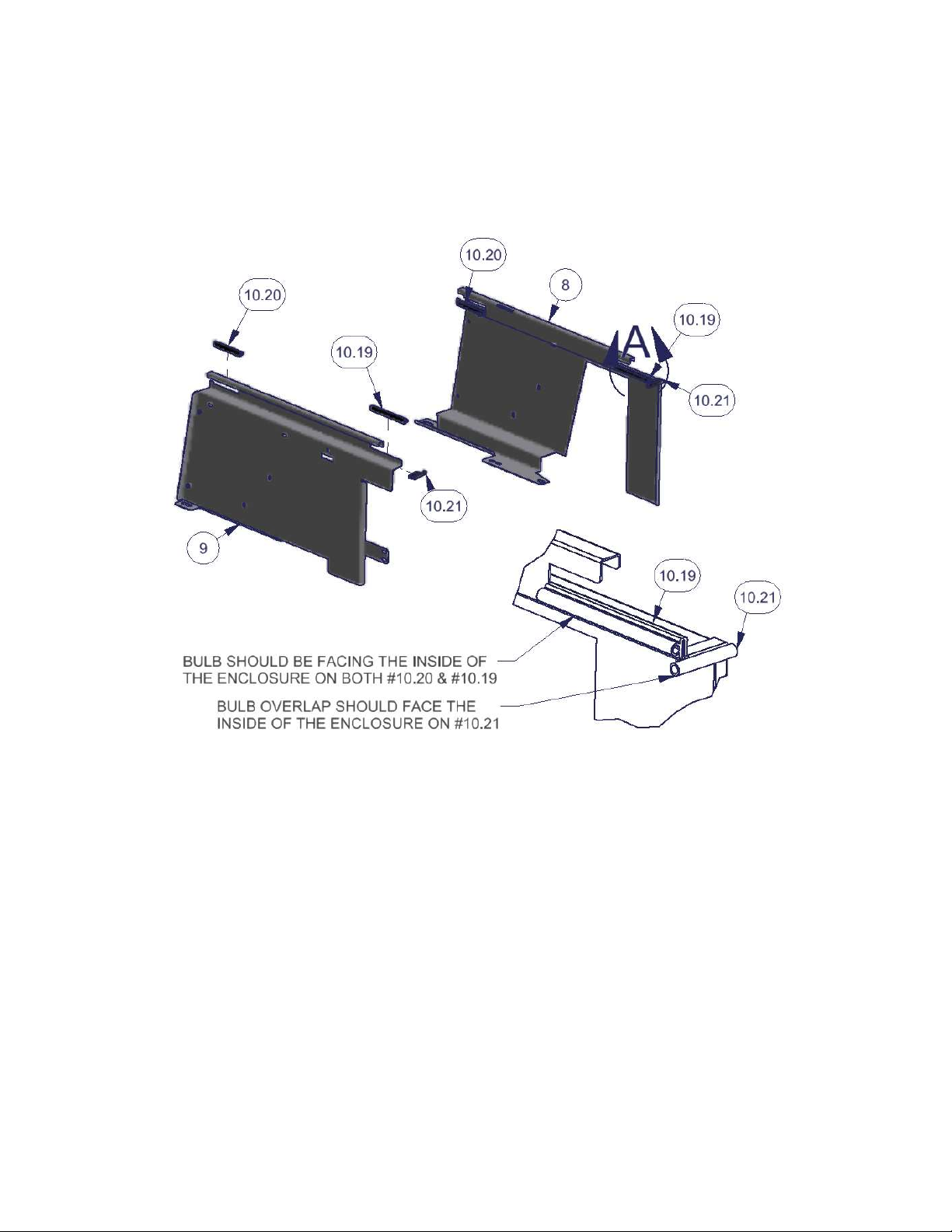
4. Install the pre-cut trim seal #10.20 and #10.19 on both sides #8 and #9 as illustrated with the bulb facing the inside of
the enclosure assembly. (See Figure 2a)
5. Install the pre-cut trim seal # 10.21 on both sides #8 and #9 with the bulb overlap protruding toward the inside of the
enclosure assembly. (See Figure 2a)
Figure 2a
6. Install the #5 Brackets to the #8 and #9 sides. The slotted holes in the #5 Brackets should be towards the outside of
the enclosure. The #5 Brackets should be mounted to the inside face of the #8 and #9 sides as illustrated. The #5
Bracket will pass through the slot in the #9 side. (See Figure 2b)
Page 3 of 8 – 12/20/06 – Rev 11/4/13
Page 4
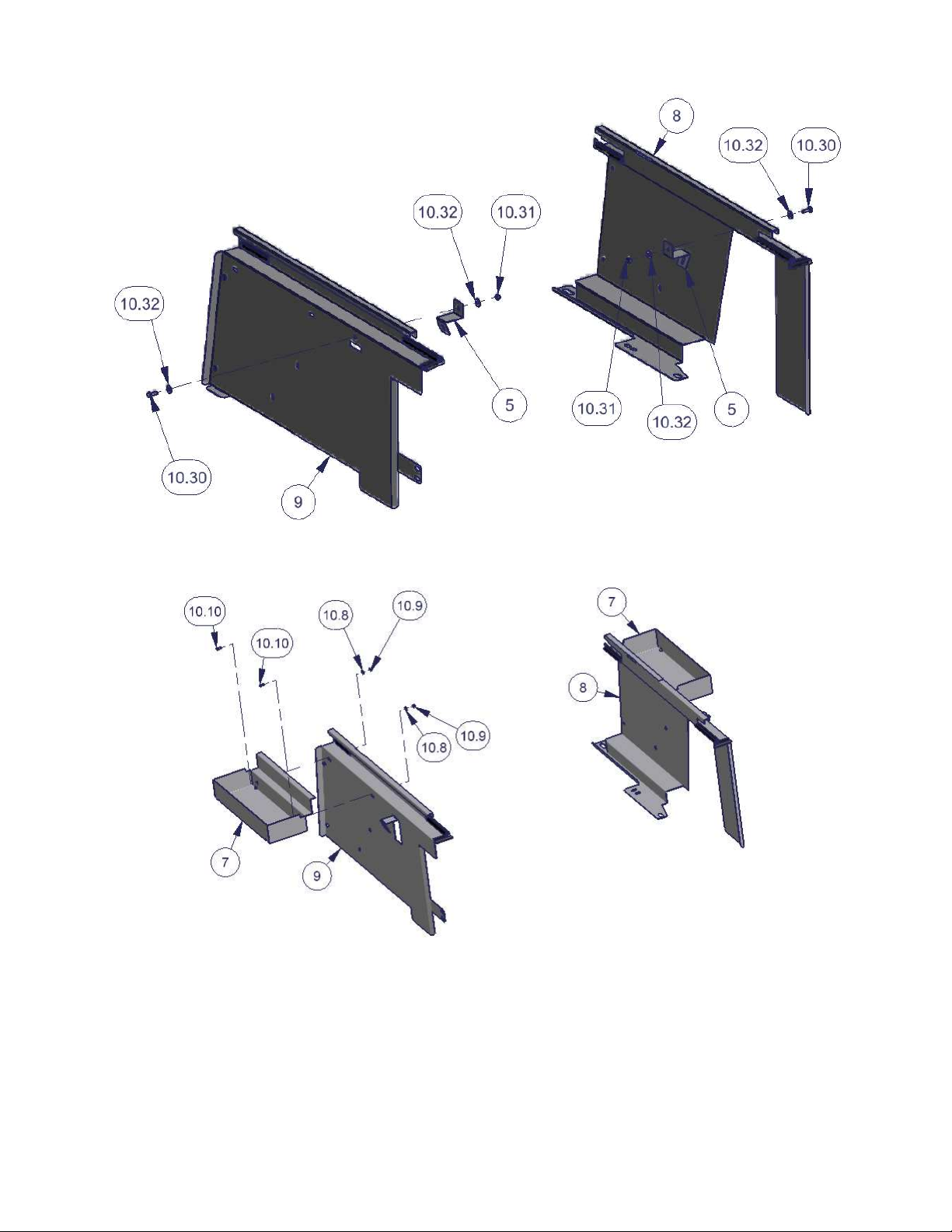
Figure 2b
7. Install the #7 trays to both sides #8 and #9 using the illustrated hardware. (See Figure 3)
Figure 3
8. All models with subwoofer only - If the vehicle is equipped with the original factory subwoofer unfasten the OEM
factory front mounting nut attaching it to the floor and also unfasten the top nut attaching it to the base of the roll bar.
(#10.2 Figure 5 shows the location when reinstalling this hardware) Save this hardware you will reuse it.
9. Unfasten the two original screws #10.3 holding the factory rear door alignment guide #10.4 and spacer #10.5 which
are mounted by the Jeep rear door latch. Save this hardware you will reuse it. (Figure 4 shows the location when
reinstalling this hardware)
10. 2-door models only - Remove rear seat in 2-door models.
Page 4 of 8 – 12/20/06 – Rev 11/4/13
Page 5
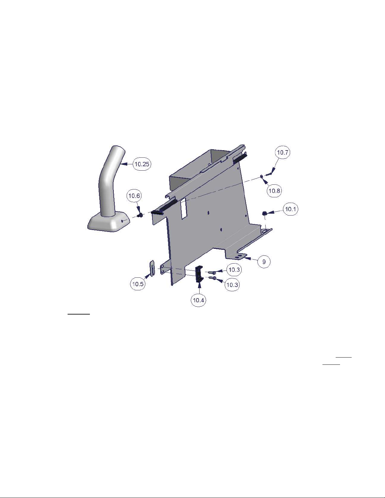
11. 4-door models only - Unfasten the two rear original factory nuts #10.1 on the rear seat mounting brackets. The two
front nuts do not need to be removed. Save this hardware you will reuse it. (See Figure 4 & 5 shows the location
when reinstalling this hardware)
12. Install the left side panel #9 by pressing the well nut #10.6 into the hex shaped hole that is located under the carpet at
the base of the roll bar mount #10.25. The carpet will need to be cut. Then fasten using bolt #10.7 and washer #10.8
through the obround hole in the #5 Bracket. (See Figure 4)
13. Fasten the left side panel #9 to the original door alignment mounting points. The door alignment spacer #10.5 should
be first then the left side panel #9 with the door alignment block #10.4 next and fasten all with the original mounting
hardware #10.3. Align the bracket by not fully tightening the screws then shutting the rear door to align the bracket
then fully tighten and check the door operation. (See Figure 4)
14. 4-door models only - Fasten the front of the left side panel #9 to the studs on top of the original seat mounting
bracket using the original nuts #10.1. (See Figure 4)
Figure 4
15. All models without subwoofer - Install the right side panel #8 by pressing a well nut #10.6 into the hex shaped hole
that is located under the carpet at the base of the roll bar mount #10.25. Also, remove the rubber plug and press a
well nut #10.6 into the hex shaped hole that is located under the carpet on the floor. The carpet will need to be cut.
Then fasten the right side panel #8 and #5 Bracket to both of these well nuts using bolts #10.7 and washers #10.8.
(See Figure 5)
16. All models with subwoofer – Position the original subwoofer #10.23 so the bottom front mounting flange is under
the bottom flange on the right side panel #8. Position the top mounting flange on the subwoofer #10.23 on top of the
right side panel #5 Bracket. Then fasten using the original nuts #10.2. (See Figure 5)
17. 4-door models only - Fasten the front of the right side panel #9 to the studs on top of the original seat mounting
bracket using the original nuts #10.1. (See Figure 5)
Page 5 of 8 – 12/20/06 – Rev 11/4/13
Page 6

Figure 5
For 2 door mounting applications do these steps. (4 door mounting applications skip past this section)
18. Slide each of the (2) Clamp brackets #11 under the (2) rear seat catch brackets inset into the floor. (See Figure 6)
19. Fasten both the Left #9 and Right #8 Side Panels to the (2) Clamp brackets #11 using #10.16 Bolts and #10.17
Washers. Be sure to tighten each bolt a little at a time to keep the pressure on the bracket even. Be careful not to
over tighten. (See Figure 6)
Figure 6
20. Fasten the #4 Rear Panel to the front of #9 left and #8 right side panels using the #10.11 knob screws. (#10.14 edge
seal on the top flange of Rear Panel #4 is installed at the factory). (See Figure 7)
Page 6 of 8 – 12/20/06 – Rev 11/4/13
Page 7
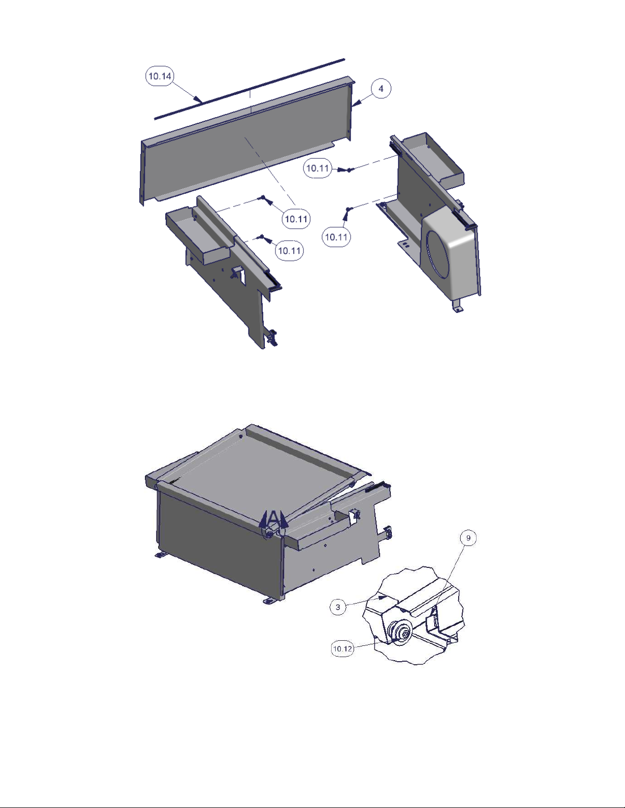
Figure 7
21. Install the lid #3 by placing it on the enclosure assembly so the welded studs with bolts #10.12 are overlapping the
enclosure toward the front of the vehicle. The end of the lid #3 with the Tuffy logo should face the rear of the vehicle.
Then pull the lid assembly toward the rear of the vehicle till it stops while guiding the welded studs into the slots on the
side panels #8 and #9. (See Figure 8)
Figure 8
22. Close the lid #3. The welded studs on the lid #3 with bolts #10.12 located toward the rear of the vehicle should now
overlap the end of the side panels. Push the lid toward the front of the vehicle till it stops while guiding the welded
studs into the slots on the side panels #8 and #9. When the rear vehicle door is shut it prevents the lid from being
pulled toward the rear releasing it from the slots. When the rear vehicle door is locked so is the Tuffy enclosure. (See
Figure 9)
Page 7 of 8 – 12/20/06 – Rev 11/4/13
Page 8

Figure 9
23. Check the seal between the vehicle rear door and the lid. Close the top rear window and check the clearance with the
lid. Loosen the mounting hardware and maneuver the enclosure so there is a good seal and clearance between the
top rear window if necessary.
Call (970) 564-1762 for Technical Support
Page 8 of 8 – 12/20/06 – Rev 11/4/13
 Loading...