

Page 1
INSTALLATION INSTRUCTIONS
QC CHECK
VISUAL INSPECTION
BEARING INSPECTION
SLIDE TEST
DRAWER STOP
RUBBER SEAL
CORRECT KEY (& COMBO
SETTING)
PUSHBUTTON LOCK TEST
COMBO LOCK TEST (IF INCL)
LATCH TEST
SHIPPING PACKAGE
DIVIDERS (IF INCL)
TRIM KIT (IF INCL)
MOUNTING KITS (IF INCL)
VERIFY CROSS BRACES
UNLOCKED WITH KEY INSIDE
QC INSPECTOR INITIALS ____________
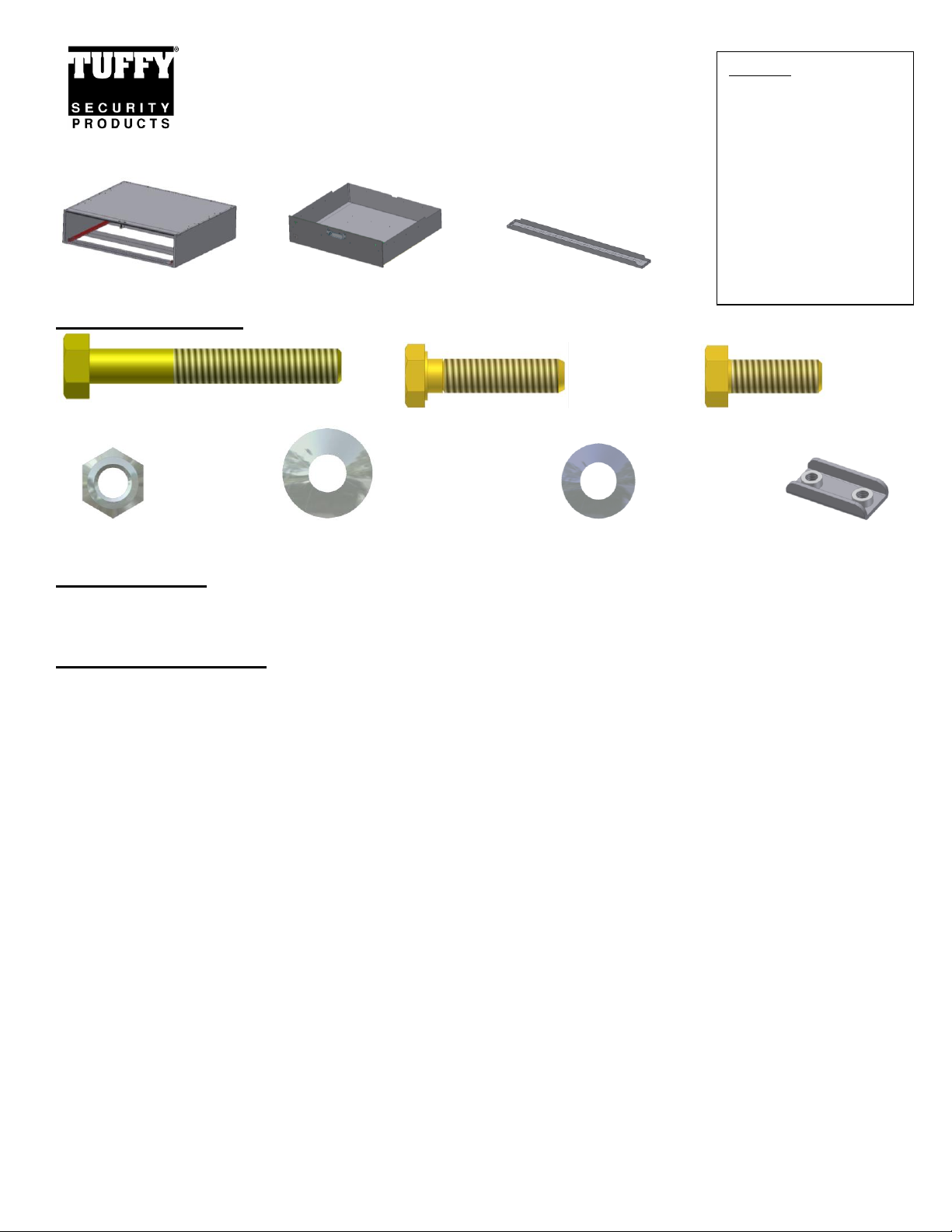
Rear Cargo Drawer – Part #167
Please read and fill out the enclosed warranty registration card to activate
your warranty.
Enclosure Drawer #8 (2) Mounting Brackets
Shipping Package
#5.2.1 (8) 5/16-18x2 1/4” Bolts #5.2.6 (8) 5/16-18x1 ¼” Bolts #5.2.4 (8) 5/16-18x7/8” Bolts
#5.2.2 (8) 5/16 Nuts #5.2.5 (8) 5/16 Wide OD Washers #5.2.3 (16) 5/16 Narrow OD Washers #14 (4) Clamps
Tools required
½” Shallow socket with a long extension and a ratchet (Universal joint also helps)
½” Wrench
Mounting Directions
WARNING! This drawer is rated to hold a maximum of 250# evenly distributed. The enclosure is rated to hold
250# on top evenly distributed. This would include any dividers mounted in the drawer. Never stand or sit on the
Tuffy drawer or enclosure. The vehicle should not be operated with the drawer opened and not secured shut.
The drawer should not be operated/opened when not level. Keep hands clear of moving parts and pinch points
when maneuvering the drawer. Do not exceed the rated weight capacity for this product.
FOR SAFETY THE DRAWER REMOVAL REQUIRES AT LEAST (2) PEOPLE. THE DRAWER SHOULD ALWAYS BE
EMPTY BEFORE REMOVING IT. CONSTANT SUPPORT MUST BE APPLIED TO HOLD UP THE FRONT OF THE
DRAWER THROUGHOUT THE ENTIRE REMOVAL PROCESS SO IT DOES NOT CAUSE INJURY AND/OR DAMAGE.
1. Check the floor and wheel well panels of the vehicle for cubby holes containing important gear or require access in an
emergency (Jack, spare tire, spare tire access, fuses, etc.). If floor access is required make sure that it is exposed
and accessible through the opening in the bottom of the drawer enclosure when the drawer is removed. Remove and
relocate any inaccessible items as required.
2. Remove drawer from enclosure. Pull the drawer out until it stops. Lift up the front of the drawer and pull it out a few
inches further until the stop bolts on the drawer slides clear the rollers on the enclosure slide. Pull the drawer again
until it stops being sure to support the front of the drawer. Pivot the front of the drawer down and lift the rear end of
the drawer out so the rollers on the drawer slides pull free through the slots in the enclosure slides. Reverse steps to
install. (See Figure 1)
Page 1 of 4 – 10/13/2010 – Rev6/8/2011
Page 2
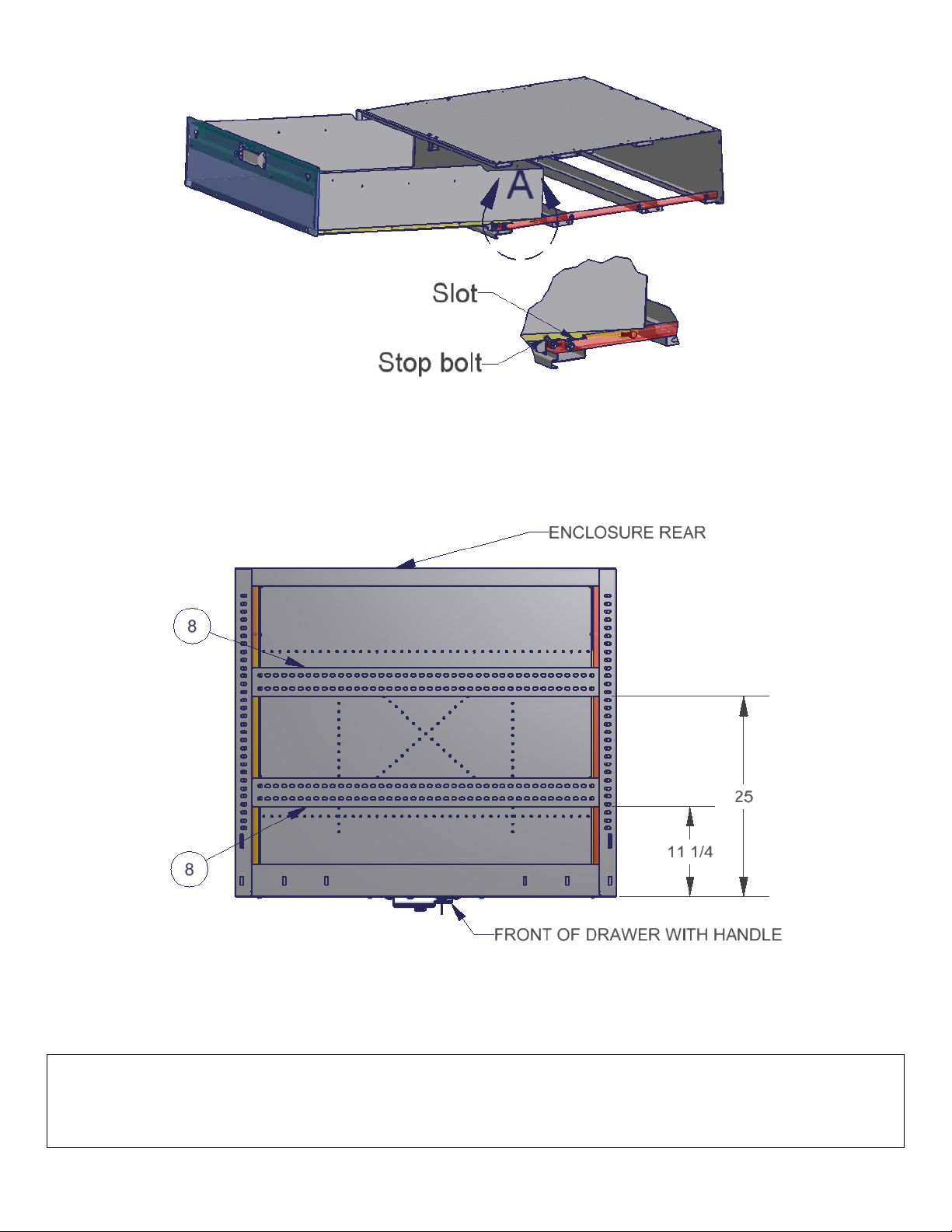
FIGURE 1
3. The drawer is shipped without the Mounting Brackets #8 installed due to the wide variety of mounting point locations
in different vehicles. Place the drawer enclosure in the vehicle in the desired mounting location and mark where the
#8 mounting brackets should be located. The #8 mounting brackets should be directly above the anchors used for the
seat mounts if available. Make sure the rear door of the vehicle shuts with the drawer installed and the seats function
properly. (See Figure 2 for the Chevy Tahoe standard mounting location)
FIGURE 2 (Chevy Tahoe standard mounting location shown, mounting bracket location varies by vehicle)
4. Remove the Enclosure from the vehicle and fasten the #8 Mounting Brackets to the enclosure with the #5.2.4 bolts,
#5.2.2 nuts and #5.2.3 washers. These bolts are difficult to reach; Use a ½” shallow socket with a long extension and
a ratchet (Universal joint also helps) and a ½” wrench on the other end. Unbolting the slide using a 7/16” wrench will
make things easier as well. (See Figure 3)
If the vehicle is not equipped with seat anchor points or the drawer requires additional mounting points you can drill 3/8”
holes in the floor aligned with holes in the #8 mounting brackets and fasten the drawer to the floor using the hardware
provided with the #14 clamps on the underside of the vehicle floor. Warning! Be sure there is nothing on the
underside of the vehicle floor which will be damaged when drilling. Most vehicles have a gas tank and gas lines
in that area.
Page 2 of 4 – 10/13/2010 – Rev6/8/2011
Page 3
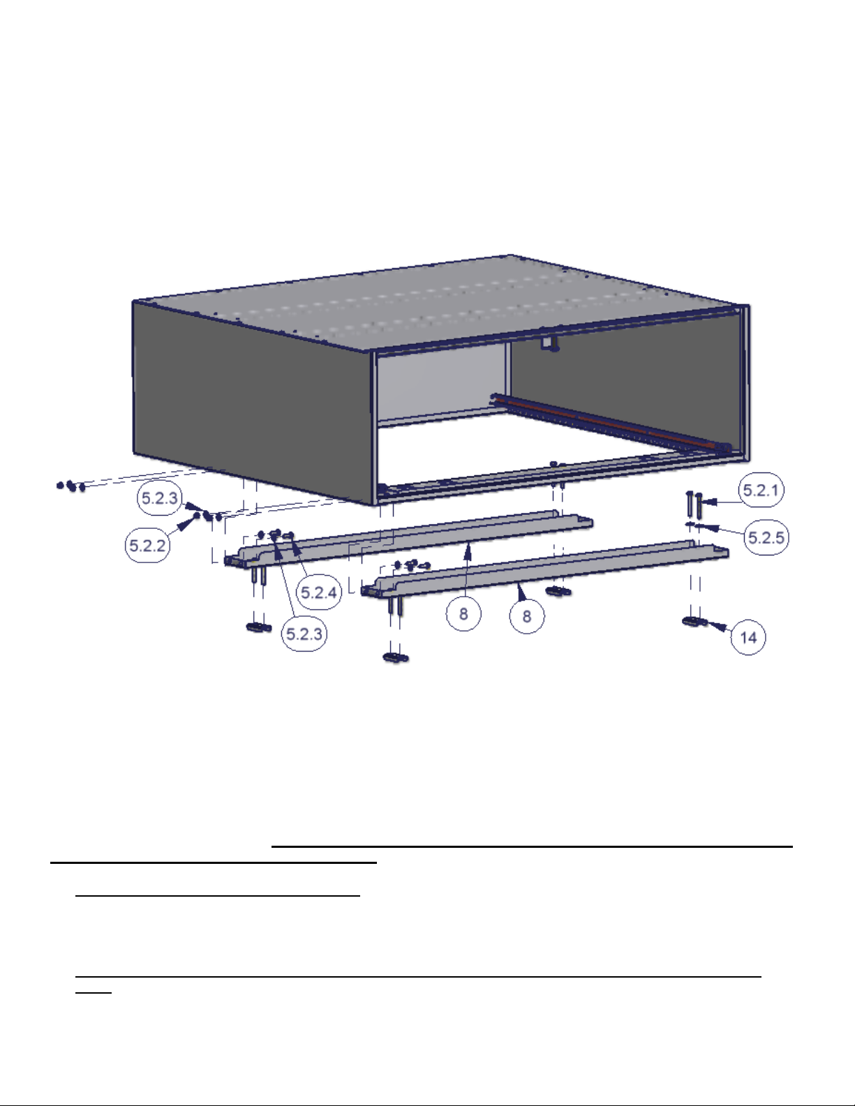
5. With the enclosure placed in the desired mounting location insert the (4) #14 clamps on the underside of the seat
anchors in the vehicle floor and using a ½” socket, extension, and ratchet fasten them to the #8 mounting brackets
with the #5.2.1 Bolts and #5.2.5 Washers (#5.2.6 Bolts are a shorter length and may alternately be required for
mounting in some vehicles). Be sure the anchor point is completely enclosed between the Bolts and is “sandwiched”
between the #14 clamp and #8 mounting bracket and cannot slip out from behind it. Do not over tighten these bolts
or damage to the #8 mounting brackets will occur due to the necessary gap. (See Figure 3)
6. Insert the drawer and test the operation. Make sure there is clearance between the drawer handle and the rear
tailgate. Test to make sure that access to any important compartments in the floor or side panels are maintained.
FIGURE 3
ATTENTION:
FREQUENT LUBRICATION IS NECESSARY ON THE LOCKING SYSTEM
The pushbutton lock contains an “O” ring seal to protect the interior from dust and water. If this mechanism is not
lubricated regularly it will become difficult to operate and it may not return to its home position preventing the key from
operating the lock. If this happens simply pull up on the pushbutton to manually bring it back to its home position.
Lubricate the pushbutton with a light lubricant such as silicone spray. The pushbutton may have to be periodically
disassembled and cleaned.
Required Periodic maintenance: Failure to perform periodic maintenance can result in the loss of access inside
the security enclosure and failure of components.
Lubrication is required for all moving parts. The schedule will vary depending on the level of usage and
environmental conditions. Once a month is a good starting point. Be sure to lubricate all friction points
completely. Use high temperature lithium grease. Key lubrication points are shown on the illustration below
for the latch system with the optional pushbutton combination lock. Some lube points in the illustration will
not be present on other latch systems. (See figure 4)
If the latch handle is removed or has been bumped out of alignment it will need to be adjusted correctly
again. The gap shown between the knob and the stop is critical and can vary slightly. If the gap is too small
the knob cannot be turned enough to unlock the latch. If the gap is too large then the knob can be turned
past its stop point which trips the internal clutch and will not unlock the latch. Adjust the handle so the gap
Page 3 of 4 – 10/13/2010 – Rev6/8/2011
Page 4

is the largest possible initially then if the clutch is tripped move it in small increments until it unlatches
correctly. (See figure 5)
All fasteners should be checked to ensure they are not loose. The schedule will vary depending on the level
of usage, environmental conditions and typical vibration encountered. Once a month is a good starting
point. Loctite may need to be reapplied after extended periods of time.
Figure 4
Figure 5
Call (970) 564-1762 for Technical Support
Page 4 of 4 – 10/13/2010 – Rev6/8/2011
 Loading...