

Page 1
INSTALLATION INSTRUCTIONS
JK Glove box Part # 149
Please read and fill out the enclosed warranty registration card to activate your warranty.
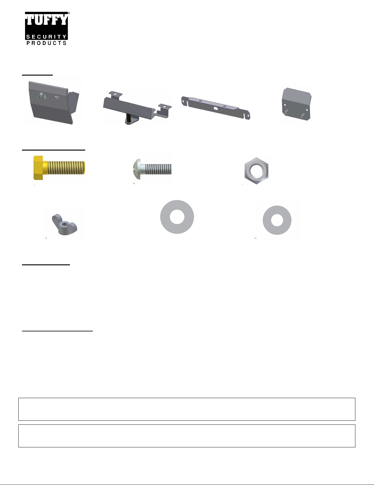
Parts list
Glove box #6 Latch Bracket #4 Mounting Bracket #3 Door Stop
Shipping Package
#13.3 (1) 5/16 X 1” Bolt #13.2 (2) ¼-20 x ¾ Screws #13.5 (1) 5/16 Nylock nut
#13.1 (2) ¼-20 Wingnuts #13.4 (2) 5/16” Washers #13.6 (2) ¼” Washers
Tools Needed
#2 Phillips head screwdriver
7mm Socket, extension, and ratchet
10mm Socket
These are only required if the optional security step is done which requires drilling
½” Socket and ½” Wrench
Drill and 5/16” drill bit
Mounting Directions
1. Remove the factory glovebox by opening it until it stops then gently squeezing the sides together so the tabs clear the
frame then rotate and pull it all the way out.
2. Remove the factory lock catch at the top of the glove box opening in the dash by unscrewing the two screws.
3. Remove the original two screws #13.7 in the dash face that attach the plastic dash panel to the frame just below each
corner of the glove box opening. Save these screws you will reuse them. (See Figure 1)
Optional step to make installation easier:
2007-2010 JK (Not applicable to 2011-up): Pop off the plastic dash panel just below the glove box opening and remove
the two screws holding the dash panel to the frame. Save these screws you will reuse them.
Optional step to make installation easier:
2007-up JK: Remove the screw on the far bottom right holding the dash panel to the frame. This screw is next to the
metal side body wall just above the ground connection. Save this screw it will be reused.
Page 1 of 2 – 12/20/06 – Rev10/12/2012
Page 2
4. Remove the original two nuts #13.8 at the top inside the glove box opening by where the lock catch was removed.
Save these you will reuse them. (See Figure 1)
5. Maneuver #4 Mounting bracket between the plastic dash panel and the frame at the bottom of the glove box opening
then re-fasten the (2) original screws #13.7. (See Figure 1) If the other original dash screws were removed they can
be re-fastened and the plastic panel can be popped back in.
6. Mount the #6 Latch Bracket to the inside top of the dash opening by re-fastening the original nuts #13.8. (See Figure
1)
OPTIONAL SECURITY STEP
WARNING! - Make sure that there is nothing behind the dash that will be damaged by the drill bit when drilling.
(2007-2010 JK) Drill a 3/8” hole in the dash frame corresponding with the center hole in Mounting Bracket #4. Fasten
using 5/16 x 1” bolt #13.3, 5/16 Nut #13.5, and 5/16” Washers #13.4. (See Figure 1)
(2011-up JK) Drill a 5/8” hole in the plastic dash panel and subsequently drill a 3/8” hole in the dash frame corresponding
with the center hole in Mounting Bracket #4. Fasten using 5/16 x 1” bolt #13.3, 5/16 Nut #13.5, and 5/16” Washers #13.4.
(See Figure 1)
7. Position the Glove box in the dash so the mounting holes by the hinge line up with the holes in the #4 Mounting
Bracket and fasten them together using (2) ¼-20 x ¾ screws #13.2 and (2) ¼ Washers #13.6. (See Figure 1)
8. Check the lock operation and fit clearances. All the mounting holes are obrounded so the fit can be adjusted by
loosening the fasteners and maneuvering the box as required.
9. Fasten the #3 Door stop to the back of the Glove box using (2) ¼-20 Wingnuts #13.1. Enable it by partially shutting
the Glove box past the #6 Latch bracket, slide the #3 Door stop up and tightening the Wingnuts. When the door is
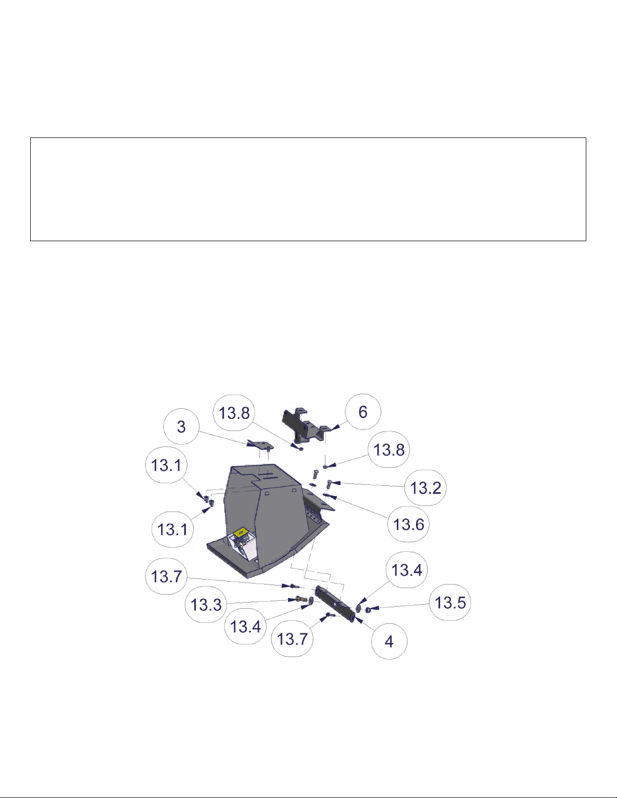
opened the #3 Door stop will hit the #6 Latch bracket preventing the door from opening further. (See Figure 1)
FIGURE 1
ATTENTION:
FREQUENT LUBRICATION IS NECESSARY ON THE LOCKING SYSTEM
The pushbutton lock contains an “O” ring seal to protect the interior from dust and water. If this mechanism is not lubricated regularly it will become
difficult to operate and it may not return to its home position preventing the key from operating the lock. If this happens simply pull up on the pushbutton
to manually bring it back to its home position. Lubricate the pushbutton with a light lubricant such as silicone spray. The pushbutton may have to be
periodically disassembled and cleaned.
Call (970) 564-1762 for Technical Support
Page 2 of 2 – 12/20/06 – Rev10/12/2012
 Loading...