

Page 1
Please read and fill out the enclosed warranty registration card to activate your warranty.
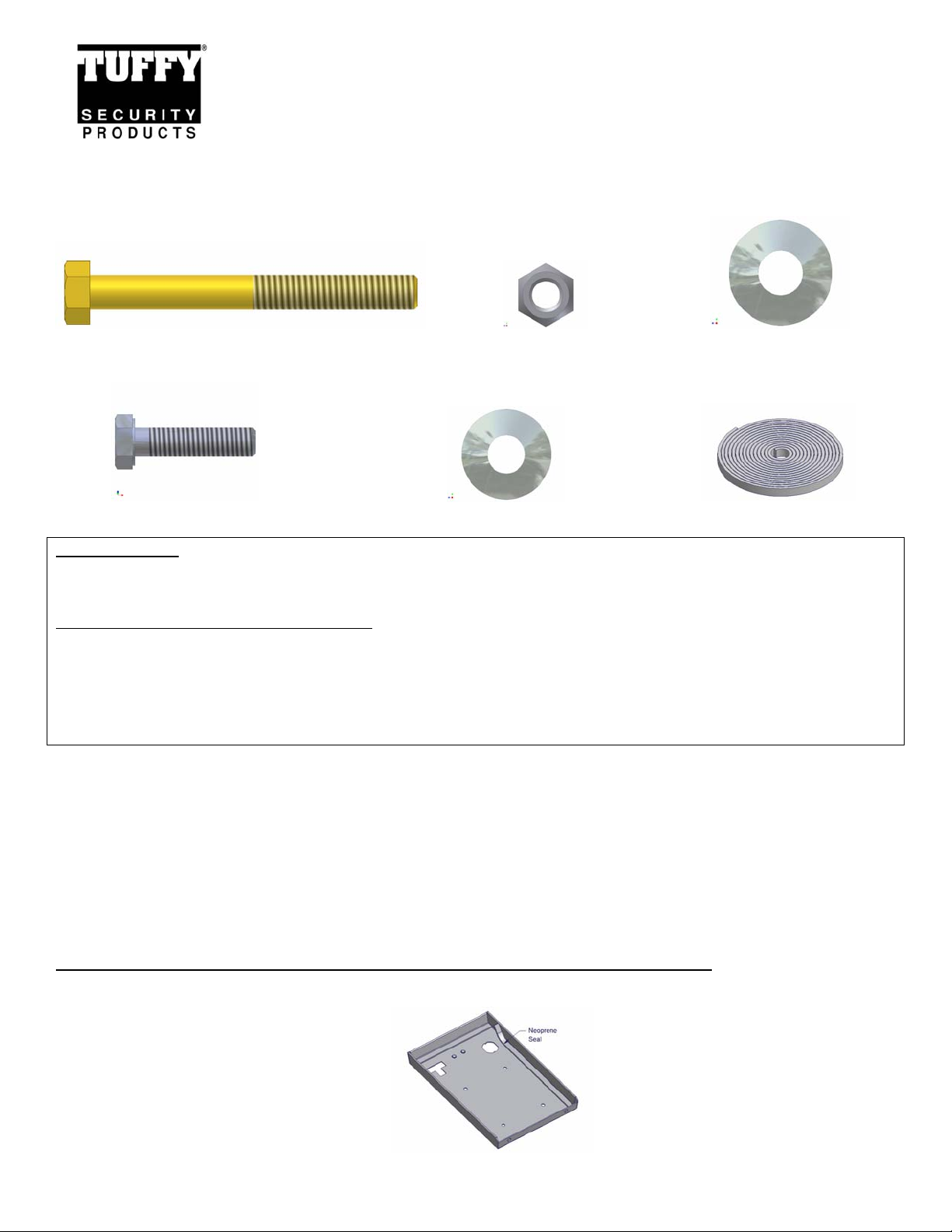
PARTS CHECKLIST
INSTALLATION INSTRUCTIONS
FJ CRUISER SECURITY CONSOLE #144
Call (970) 564-1762 for Technical Support
#6.5 (1) 5/16-18 x 3” HEX CAP SCREW, GRADE 8 #6.4 (1) 5/16-18 LOCKNUT #6.3 (2) 5/16” WASHERS
#6.6 (2) 6MM X 25MM HEX CAP SCREWS #6.7 (2) ¼” WASHERS RUBBER SEAL
TOOLS NEEDED
• 10MM Socket, extension, and ratchet
Tools for optional additional mounting security
• Electric drill
• 3/8” Drill bit
• Marker or pencil
• Silicone sealant (Reco mmended)
• ½” Socket and ratchet
• ½” Wrench
ATTENTION:
FREQUENT LUBRICATION IS NECESSARY ON THE LOCKING SYSTEM
The pushbutton lock contains an “O” ring seal to protect the interior from dust and water. If this mechanism is not lubricated regularly
it will become difficult to operate and it may not return to its home position preventing the key from operating the lock. If this
happens simply pull up on the pushbutton to manually bring it back to its home position. Lubricate the pushbutton with a light
lubricant such as silicone spray. The pushbutton may have to be periodically disassembled and cleaned.
PLEASE READ ALL INSTRUCTIONS THOROUGHLY BEFORE STARTING INSTALLA TION.
1. Install the rubber seal around the edge of the lid and check the lock and latch operation. (See Figure 1)
FIGURE 1
Page 1 of 2 - 01/28/2008 – Rev02152006
Page 2
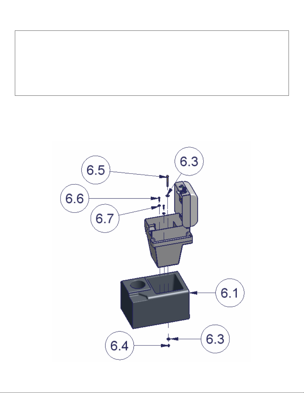
2. On the original OEM console #6.1 pull out the rubber floor insert in the tray and unscrew the (2) original 6MM screws.
OPTIONAL ADDITIONAL SECURITY STEP
3. Place the Tuffy console in the original OEM console tray #6.1 and line up all the mounting holes with the (2) threaded holes in
the bottom of the tray. Mark the spot on the original console under the 3/8” hole in the bottom of the Tuffy console for drilling.
(See Figure 2)
WARNING! Make sure that there is nothing under/on the vehicle that will be damaged by the drill bit when drilling,
the emergency brake cables are close so don’t push the drill bit through past ¼”.
4. Remove the Tuffy insert and drill a ¼” pilot hole in the marked spot then drill it out to 3/8”. Use touch up paint or silicone
sealant in any drilled holes to prevent rusting.
5. Fasten the console assembly down using the (2) provided 6MM x 25MM screws #6.6 and (2) ¼” Washers #6.7. (See Figure 2)
6. If the optional additional security step was done fasten down the Tuffy console using a 5/16-18 x 3” Hex cap screw #6.5, a 5/16”
Locknut #6.4, & (2) 5/16” washers #6.3 through the hole previously drilled. Do not over tighten. (See Figure 2)
FIGURE 2
Page 2 of 2 - 01/28/2008 – Rev02152006
 Loading...