

Page 1
Please read and fill out the enclosed warranty registration card to activate your warranty.
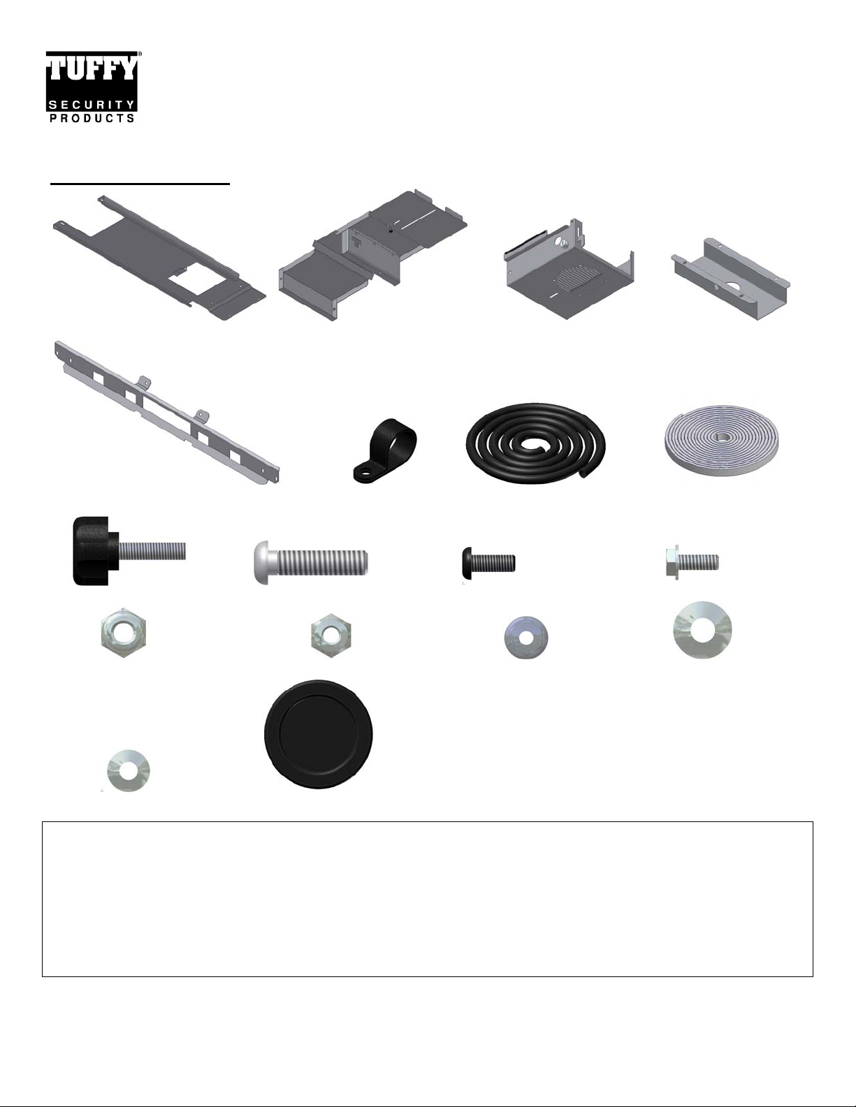
Shipment Contents
INSTALLATION INSTRUCTIONS
Single Compartment Overhead Console #142
#12
#8 Windshield Mounting Bracket #7.9 Wire Clamp #7.20 Wire Loom #9.15 Rubber Seal
#9.13 10-32x3/4 Knob Screw #7.13 (2) ¼-20x1 Screw #7.19 (7) 10-32x1/2 Allen Screw #7.10 (4) 10-32x1/2 Hex Screw
#7.14 (2) ¼-20 Nylock Nut #7.3 (4) 10-32 Nylock Nuts #7.11 (3) 10-32 Flange Nuts (7.15) ¼” Washers
Top Panel Slide Assembly #1 Electronics Mounting Bracket #4 Clamp Bracket
#7.2 (5) #10 Washers #7.1 (2) 1” Grommets
TOOLS / PARTS NEEDED
• T-25 Torx wrench
• 1/8” Allen Wrench or socket
• 5/32” Allen Wrench or socket
• 5/16” Wrench and/or socket
• Ratchet and 3/8” socket, 7/16” so cket, & 10mm socket
• Black Electrical tape
• Any electrical wires, connectors, etc. to install ele ctro nic equipment. (Read com pleted instructions prior to making this
list of parts to avoid unnecessary trips to the store)
Page 1 of 6 - 3/6/2009 – Rev030609
Page 2

PLEASE READ ALL INSTRUCTIONS THOROUGHLY BEFORE STARTING INSTALLA TION.
1. Install the #7.7 electronics equipment (Not included) in the #1 Electronics mounting bracket using the hardware illustrated #7.19
and #7.1. #7.12 is a stereo support strap that usually comes with the stereo. Plummer’s strap, which can be purchased at any
hardware store, can be substituted and is also helpful when mounting CBs or other equipment. Check to make sure nothing is
protruding more than 1 1/8” out of the front or the lid will not close. (See Figure 1)
2. Install the #7.1 grommets in both 1” holes in the #1 Electronics mounting bracket. If a CB is mounted and you would prefer the
MIC to be accessible when the lid is closed a small slit can be cut in either grommet (Passenger side is recommended) and the
MIC cable can be inserted through it and plugged in provided there is enough space in front of the CB so the lid can close. (See
Figure 1)
WIRING WARNINGS AND TIPS:
• Follow the manufacturer’s directions for connecting the supply wires to your electronic equipment.
• It is recommended to run all the wires possible from the source (Power, Speakers, etc.) along the roll bar, protected under
the padding to the upper corner of the sport cage. Then follow the instructions in the following steps to run corresponding
wires from the electronics equipment in the Tuffy Overhead console to the locations on the upper corner of the sport cage.
Then use electrical connectors to join the wires.
• Be sure to mark the wires so they can be matched up correctly.
• An antenna extension wire may be required and can be purchased at most Radio Shack locations or other electronic
equipment providers.
• Always make sure wiring is protected from rubbing against sharp edges which can and will cause shorts and potentially
damage electronic equipment.
3. Insert the wiring harness in the #7.2 wire loom and route it as illustrated. It should not be bunched up on top of the electronics
equipment. This is critical; the overhead console is designed so the electronics assembly can be slid back to access the levers for
removing the tops. When it is slid back the wire loom must be able to fill this area or the sliding action will be prohibited. Make
sure the wiring is fully protected inside the #7.2 wiring loom and electrical tape to prevent damage when the electronics
equipment is slid forward and back. (See Figure 1)
4. Fasten the slide assembly to the #1 Electronics mounting bracket using the illustrated hardware #7.19. Make sure #7.2 wire loom
is routed as illustrated. (See Figure 2)
5. Apply the Rubber Seal provided to the lid so that it will seal up against the #1 Electronics bracket when closed. Check the lid and
lock operation.
6. Slide the Electronics assembly through the front of the #12 Top Panel. Push it in until the front wire clamp hole for #7.19 screw
is only exposed by about ½”. Pull the #7.2 Wire loom snug and mark it where both #7.9 clamps will be located. (See Figure 3)
7. Remove the Electronics assembly and insert the #7.9 Wire clamps in the correct orientation at the correct locations on the #7.2
wire loom and using electrical tape secure the clamps so they will not move forward or back on the wire loom. This is critical so
that the wire loom will not bunch up in the wrong location and prevent the sliding action. Make sure the wiring is fully
protected inside the #7.2 wiring loom and electrical tape to prevent damage when the electronics equipment is slid forward
and back. (See Figure 3)
8. Slide the Electronics assembly back through the front of the #12 Top Panel. Fasten the #7.9 Wire clamps to the #12 Top Panel
using the illustrated hardware #7.19 and 7.11. Do not over tighten these screws. (See Figure 3)
9. Fasten the slide assembly to the #12 Top panel using the Knob Screw #9.13 and Washer #7.2. (See Figure 3)
10. Test the slide action by loosening the #9.13 knob screw then sliding the assembly forward and back. Inspect that the wiring is not
bunching up preventing movement and is not rubbing against any sharp edges which can potentially damage electronic
equipment. Adjust as required for adequate movement. (See Figure 6)
11. Remove the “T” tops (or lower the soft-top). Consult your veh icles owners’ manual for removal instructions.
12. Remove the OEM plastic top windshield frame cover #7.21. To do this pull firmly at the center bottom to pop out (6) catches
then un-tuck the ends. (See Figure 4)
13. Unfasten both loop catches #7.5 (Not the center one) by removing the #7.16 screws. You will reuse all these. (See Figure 4)
Page 2 of 6 - 3/6/2009 – Rev030609
Page 3

14. Insert the #8 Windshield mounting bracket over the center loop catch as illustrated then refasten both #7.5 loops with the original
hardware #7.16. (See Figure 4)
15. Re-install the #7.21 cover by tucking the ends in then aligning the inserts and pressing firmly to pop it securely in. (See Figure 4)
16. Remove the #7.6 factory sound bar by removing the 6 mounting screws and unplugging the wiring harness. Save all this
hardware it will all be reinstalled. (See figure 5)
NOTE: Having the necessary parts and hardware within reach before starting the following steps will make the installation
process easier.
17. Place the Tuffy Overhead Console as illustrated and fasten the holes on the front of #12 Top Panel to the corresponding holes in
the #8 Windshield Mounting Bracket and with the Tuffy Overhead console as far forward as possible fasten it using the provided
hardware #7.13, 7.15, and #7.14. Make sure the rear of #12 top panel is resting on top of the sport cage #7.4. (See Figure 5)
18. With the Tuffy Overhead Console centered fasten the rear of #12 Top Panel to the sport cage bar #7.4 using the #4 Clamp bracket
around the bottom and fastening it with the illustrated hardware #7.1, #7.2 and #7.3. (See Figure 5)
19. Connect the Electronics equipment in the Tuffy Overhead console and check the operation. Follow the manufacturer’s
directions for connecting the supply wires to your electronic equipment. (See Figure 5)
20. Reinstall the original #7.6 sound bar using the (6) original screws. Don’t forget to plug the wiring harness back in. (See Figure 5)
21. Reinstall the front tops. To access the clamps for the top installation and removal by loosen #9.13 knob screw and sliding the
electronics assembly toward the back to expose the #7.18 top front lever. (This #7.18 lever is in an alternate location on early
JK’s) Once all the exposed top levers have been undone, if there is still a difficult to reach lever still engaged behind the Tuffy
Overhead console, both tops can be lifted up together and shifted to the side to expose any other hard to reach lever. (See Figure
6)
22. Be sure to keep the #9.13 Knob screw tight at all times and do not operate the vehicle with the electronics assembly not slid all
the way forward. (See Figure 6)
Page 3 of 6 - 3/6/2009 – Rev030609
Page 4

FIGURE 1
FIGURE 2
Page 4 of 6 - 3/6/2009 – Rev030609
Page 5

FIGURE 3
FIGURE 4
Page 5 of 6 - 3/6/2009 – Rev030609
Page 6

FIGURE 5
FIGURE 6
Call (970) 564-1762 for Technical Support
Page 6 of 6 - 3/6/2009 – Rev030609
 Loading...