

Tuff Torq K92 Service Manual


T a b l e o f C o n t e n t s
4WD Output Disassembly and Assembly .................................................................. 24
Brakes Removal and Installation ................................................................................ 43
Center Valve Block Disassembly and Assembly ...................................................... 33
Charge Pump Disassembly and Assembly ................................................................. 2
Charge Pump Removal and Installation ...................................................................... 2
Control Arm and Damper Removal and Installation ................................................... 1
Differential (2WD) Disassembly and Assembly ........................................................ 20
Differential (4WD) Disassembly and Assembly ........................................................ 21
Differential Lock Shaft Disassembly and Assembly ................................................. 19
General Specifications ................................................................................................... iv
Hydrostatic Flow Diagram Check Points ................................................................... 44
Hydrostatic Pump Inspection ....................................................................................... 35
Hydrostatic Transmission 2WD and 4WD ................................................................. 28
Hydrostatic Transmission Installation ......................................................................... 35
Hydrostatic Transmission Motor Disassembly and Assembly (2WD) ................... 29
Hydrostatic Transmission Motor Disassembly and Assembly (4WD) ................... 31
Hydrostatic Transmission Motor Installation ............................................................. 34
Inspection of Transaxle Case ...................................................................................... 39
K92 Transmission Component Location ..................................................................... vi
Ordering Replacement Parts Online ............................................................................. ii
PTO Brake Removal and Installation ........................................................................... 6
PTO Clutch Disassembly, Inspection and Assembly ............................................... 22
PTO Drive Train (Mid-PTO) Removal and Installation .............................................. 9
PTO Drive Train (Mid and Rear PTO) Removal and Installation ........................... 11
PTO Relief Valve Disassembly, Inspection and Assembly ....................................... 6
PTO Relief Valve Removal and Installation ................................................................ 6
PTO Solenoid Valve ........................................................................................................ 4
Rear Axle Assembly - Disassembly and Assembly .................................................. 42
Rear Axle Assembly Removal and Installation ......................................................... 41
Rear PTO Assembly ..................................................................................................... 17
Rear PTO Removal and Installation ........................................................................... 14
Recommended Tools and Equipment ......................................................................... iv
Serial Number Location ................................................................................................. iv
Transaxle (Right Cover) Disassembly and Assembly .............................................. 38
Transaxle Disassembly ................................................................................................ 36
Troubleshooting Guides ............................................................................................... 46
i
Ordering Replacement Parts Online
w w w . t u f f t o r q . c o m
Home
Page 1
Page 2
Page 3
At Tuff Torq, we offer our customers quality
products at a modest price. A manufacturer
of hydrostatic and gear drive transmissions
for the power equipment industry, Tuff Torq
offers a complete line of transmissions and
parts to help fit your needs.
Designed to meet the needs of our OEM custom-ers,
this web site is designed to assist service and re-pair
facilities in locating and ordering parts for Tuff Torq
manufactured transmissions. It also provides
transaxle parts identification, troubleshooting
guides, online ordering capabilities, as well as
providing you with a complete inventory of parts,
service and same day shipping.
If you are a registered user, please login (from the
Welcome Page) to access the parts ordering system.
If you are not a OEM customer or authorized
service distributor, you may need to contact your
equipment manufacturer or authorized dealer.
Select your brand (from the Welcome page) and
you will be directed to the appropriate web site.
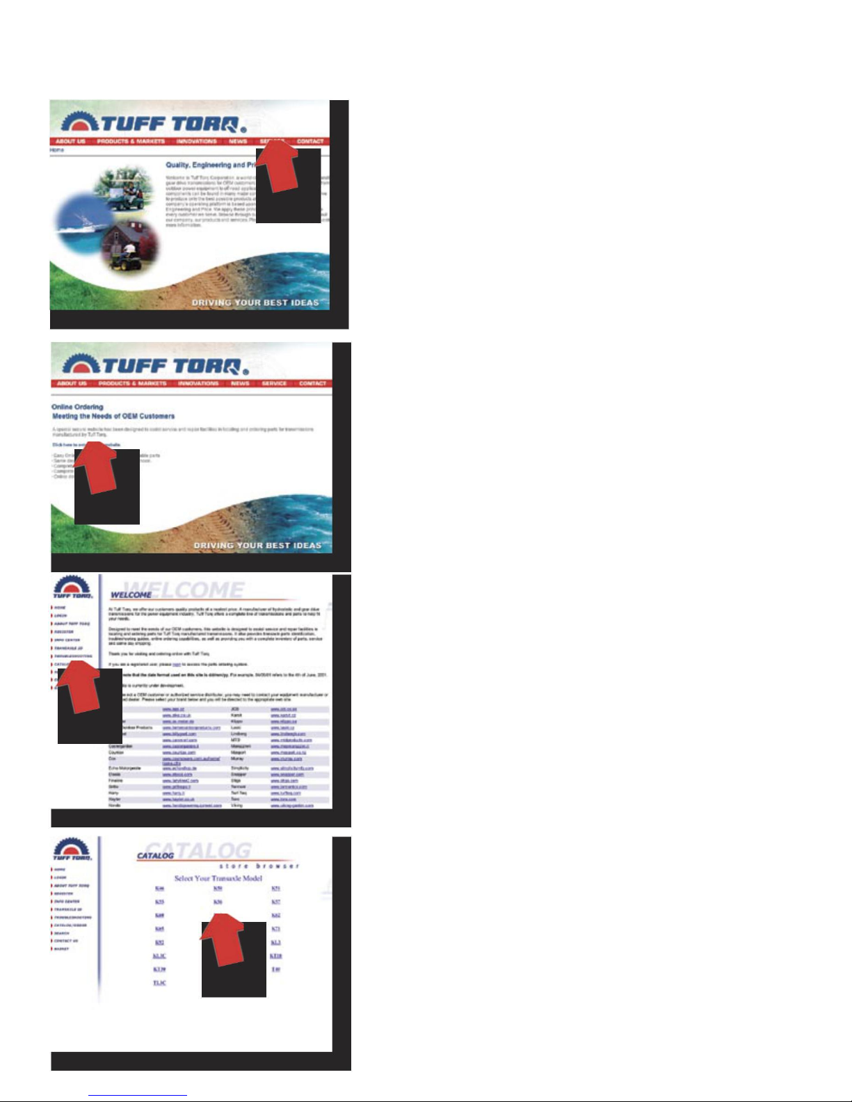
Navigating the web site:
To access Tuff Torq’s web site, type in www.
tufftorq.com from your Internet browser. From
the Home page, click on “Service” to enter the
Online Ordering page (Ref. Page 1)
From The Online Ordering page, click on “Click
here to enter service web site” to enter the
Welcome page (Ref. Page 2).
From the Welcome page, login (for register
users) and follow the on screen instructions. Or,
click on “Catalog/Order” to enter Store Browser
(Ref. Page 3).
From the Catalog/Order page, select your
transaxle model, e.g., K61. Click on “K61” to find
the serial number for your model (Ref. Page 4).
From the Model Series page, click on, your Model to
enter the Serial Number Range page (Ref. Page 5).
ii
Page 4
Page 5
Page 6
Page 7
Tuff Torq K92 Hydrostatic Transaxle
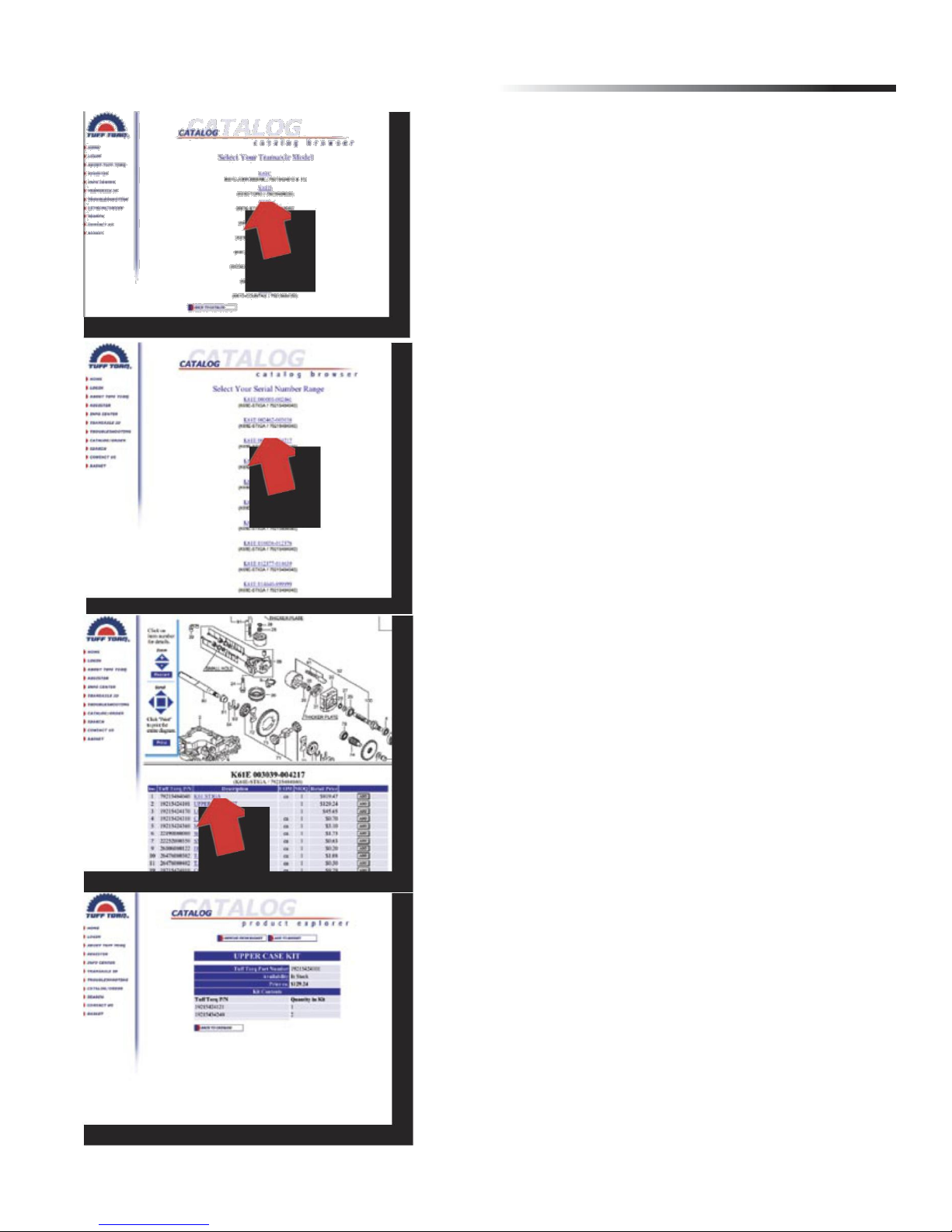
Having your Model, and Model Series, click on
the serial number to enter the Online Ordering
page for you Transaxle (Ref. 6).
Navigate through the exploded parts illustration until
the desired part has been identified. Take note of the
part’s figure number. Locate the part number in the
parts listing. You can add the part to your shopping cart
and return to the exploded illustration or—click on the
item to go to the Product Explorer page for additional
detail about the part (Ref. Page 7).
Thank you for visiting and ordering online with
Tuff Torq.
iii
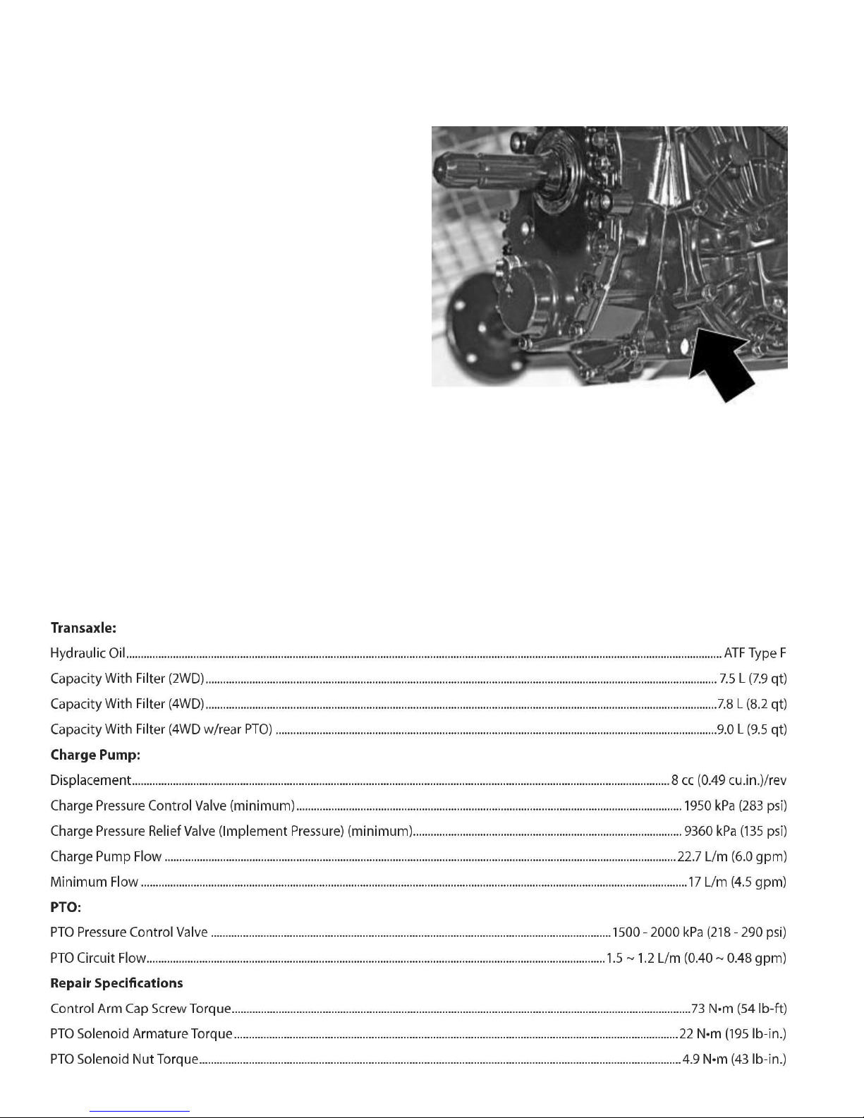
Recommended Tools and Equipment Serial Number Location
1. Solenoid Valve Socket
2. Transmission Gear Spacer
3. Bushing, Bearing and Seal Driver Set
4. Press
5. Snap Ring Pliers
6. Knife-Edge Puller
7. Hoist
8. Silicon Sealant
9. Cure primer
10. Thread Lock and Sealer (Medium Strength)
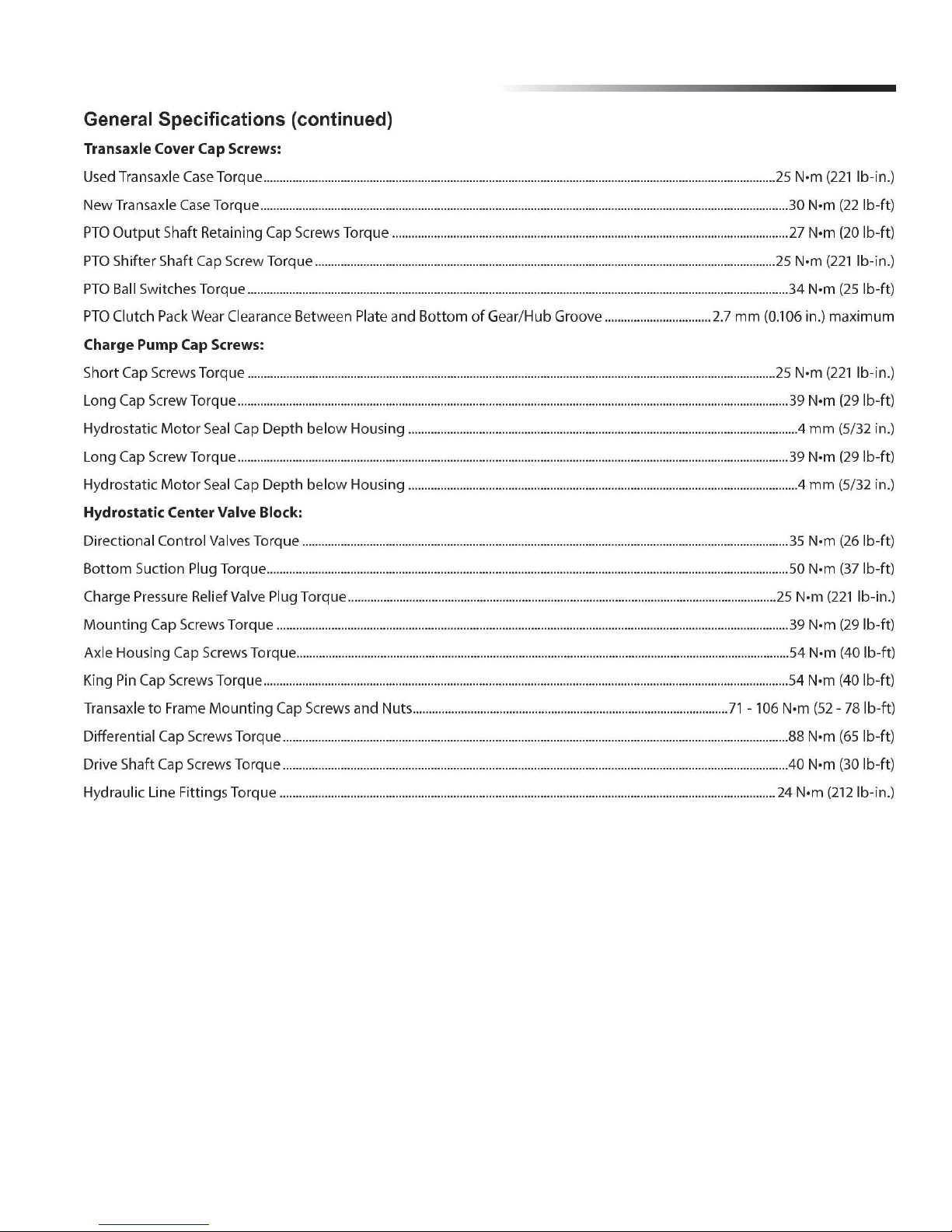
General Specifications
iv
Tuff Torq K92 Hydrostatic Transaxle
v
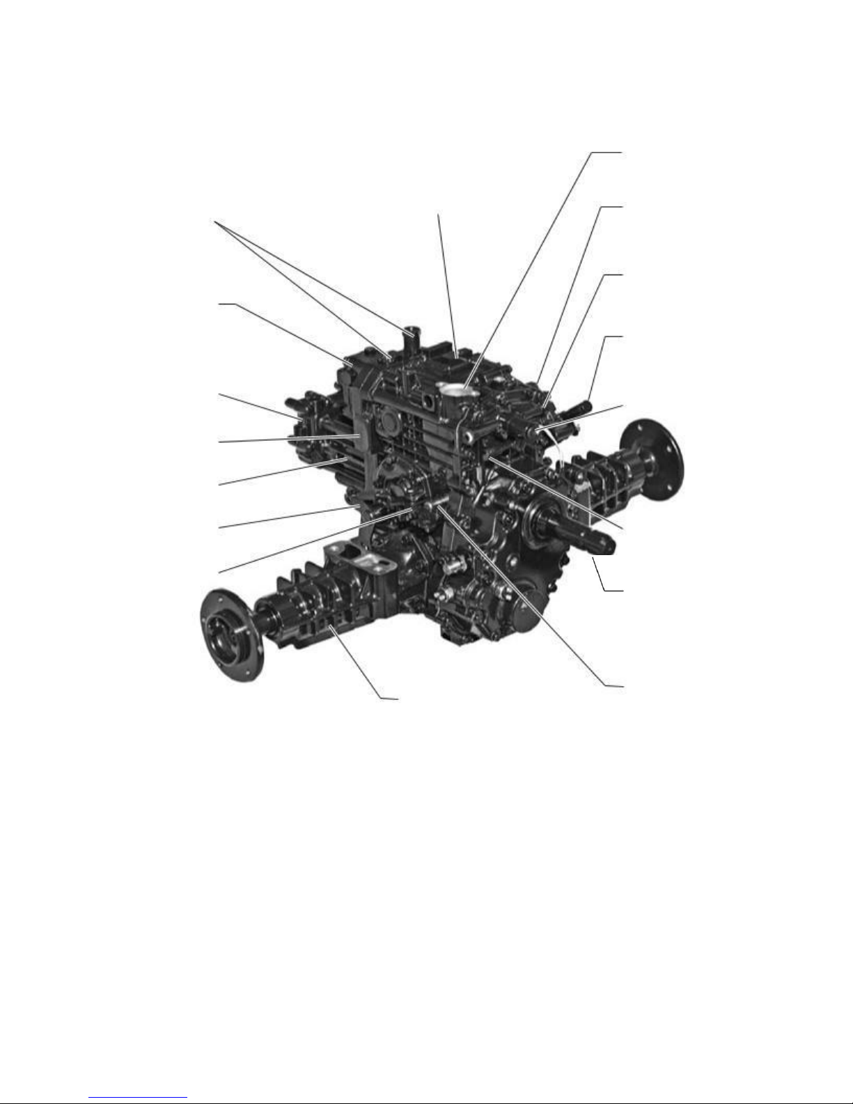
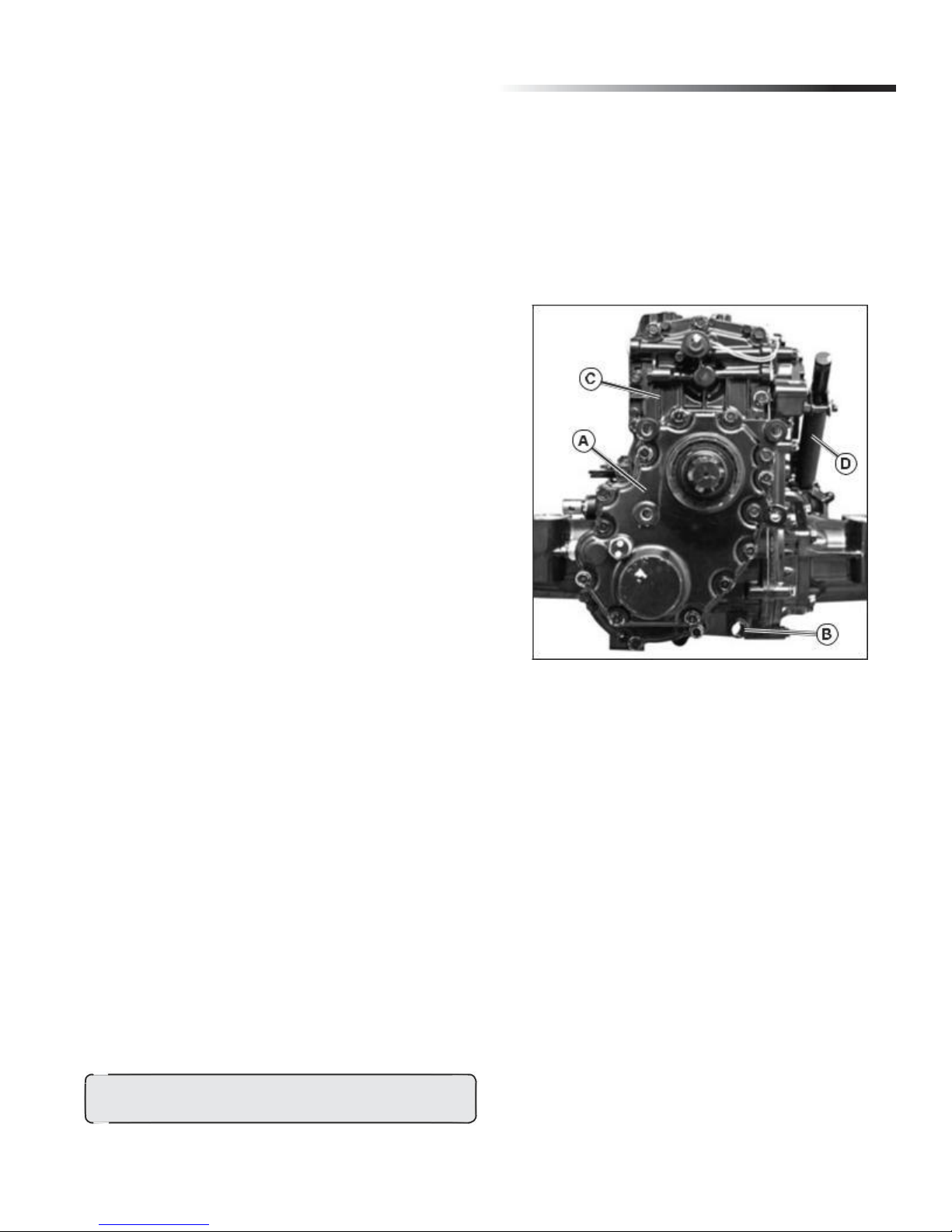
K92 Transmission Component Location
Forward/Reverse
Main Transmission Case
Control Valves
Charge Pump
4WD Assembly
(Optional)
Center Block Valve
Motor Case Assembly
Brake Arm/
Brake Assembly
Differential Lock Arm
Axle Assembly
K92 Hydrostatic Transaxle
Oil Port
(Fill Tube not Shown)
PTO Brake Cover
PTO Pressure
Test Port
Control Arm Damper
PTO Electrical
Engagement Solenoid
PTO Pressure
Control Valve
Rear PTO Shaft
(Optional)
Differential Lock Shaft
vi
Tuff Torq K92 Hydrostatic Transaxle
Control Arm and Damper Removal and Installation
Before beginning tear down clean work area thoroughly
and cover workbench with clean paper. This is extremely
impor-tant as just one grain of sand can cause damage to
the Hy-drostatic Rotating Group in the Transaxle.
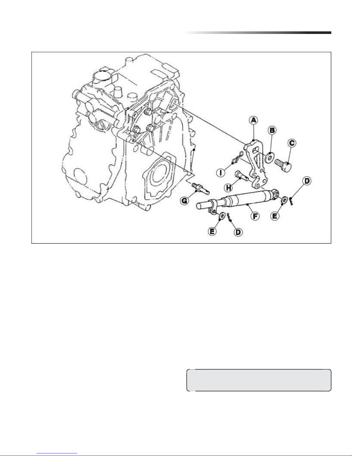
Fig. 1, Control Arm and Damper Disassembly
A - Control Arm
B - Washer
C - Main Cap Screw
D - Spring Locking Pin
E - Washer
F - Damper
G - Pivot Stud
H - Clevis Pin
I - Spring Locking Pin
1. Remove spring locking pins (D) and washers (E)
from both sides of damper (F). (Fig. 1)
2. Slide damper off of pivot stud (G) and clevis pin (H).
Inspect and, if defective, replace damper as an assembly.
3. To remove control arm (A), remove spring locking pin (I)
and disconnect foot control rod (D) from control arm.
4. Remove cap screw (C) and washer (B) from
control arm. (Fig. 1)
5. Remove control arm (A). (Fig. 1)
6. Install control arm the same as removal, and install
washer and cap screw. Tighten cap screw (C) to
73 N•m (54 lb-ft).
NOTE: If removed, use medium strength thread
lock and sealer on pivot stud (G) threads.
7. Install damper with open end of clamp facing down.
8. Install remaining washers and spring locking pins.
CAUTION: ALWAYS WEAR SAFETY GLASSES WHILE PER-
FORMING ANY MAINTENANCE ON TRANSAXLE!
NOTE: Access to cap screw (C) is through hole in
right frame.
1
Charge Pump Removal and Installation
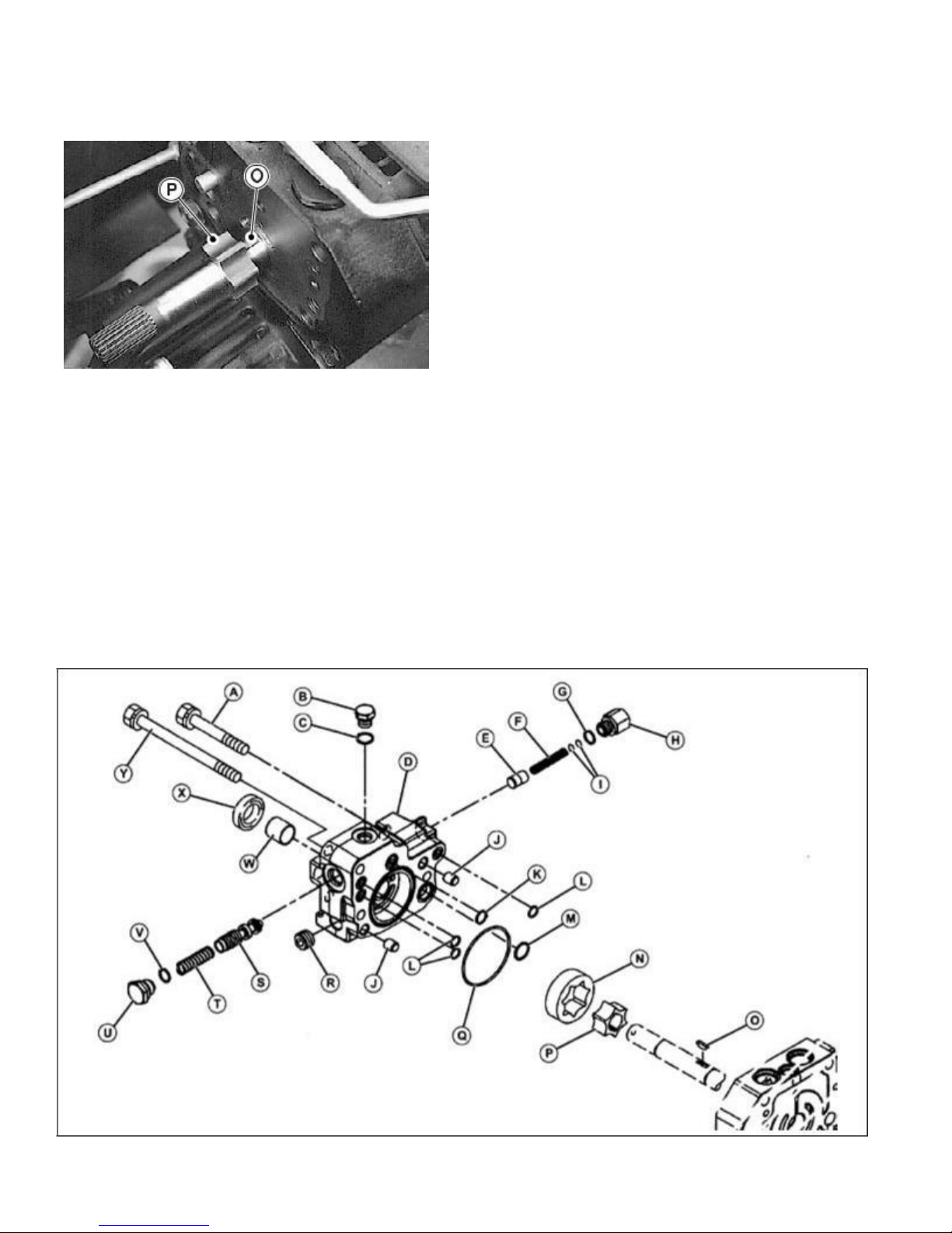
Fig. 2, Charge Pump Rotor
IMPORTANT: Avoid damage! Do not drop pump
gerotor (P) or lose key (O). Damage to machined
surfaces will cause poor performance and premature
failure. (Fig. 2)
1. Remove drain plug to drain oil before starting any
disas-sembly of the transaxle.
2. Remove two (2) short (A) and one long (Y) cap screw.
(Fig. 3)
Charge Pump Disassembly and Assembly
NOTE: Installation is done in the reverse order of removal.
• Tighten (2) short cap screws (A) to 25 N•m (18 lb-ft).
• Tighten long cap screw (Y) to 39 N•m (29 lb-ft).
NOTE: Approximate capacity of hydrostatic power train
is 7.5L (7.9 qt) for 2WD and 7.8L (8.2 qt) for 4WD and
9.0L (9.5 qt) for 4WD w/rear PTO.
Fig. 3, Charge Pump Disassembly
2

Tuff Torq K92 Hydrostatic Transaxle
Charge Pump Disassembly and Assembly (continued)
A - Cap Screw (2 used), M10 x 65
B - Plug
C - O-ring
D - Pump Body
E - Pressure Valve
F - Spring
G - O-ring
H - Plug
I - Shims
J - Pin
K - O-ring
L - O-ring
M - O-ring
N - Outer Rotor
O - Key
P - Inner Rotor
Q - O-ring
R - Plug
S - Reducing Valve
T - Spring
U - Reducing Plug
V - O-ring
W - Bushing
X - Seal
Y - Cap Screw, M10 x 105
6. Check small orifice in reducing valve (S) spool
for obstruction.
7. Replace parts if necessary.
8. Remove plug (H) to remove charge pressure relief
valve parts (E, F, G, and I). (Fig. 3)
9. Inspect parts for scoring, wear or damage.
10. Replace parts if necessary.
11. Inspect seal (X) and bushing (W) for wear or damage.
12. If bushing is removed, apply clean hydraulic oil to
bushing and use a disk driver to install bushing to
bot-tom of bore.
13. If seal is replaced, apply clean hydraulic oil to new
seal. Install seal with open side into pump body.
Push seal to bottom of bore.
14. Apply clean hydraulic oil to all machined surfaces
before assembly.
NOTE: Installation is done in the reverse order of removal.
NOTE: Charge pressure control valve and pressure
reducing valve can be removed when the charge pump
is in the machine. To inspect valve seats and bores,
the pump must be removed.
1. Disassemble all parts of charge pump (D). (Fig. 3)
2. Inspect O-rings (C, K, L, M, and Q) for cuts or
damage. Replace as necessary. (Fig. 3)
NOTE: Pump gerotor (N and P), seal (X), body (D), and
pressure reducing valve (S) parts must be replaced as a set.
3. Inspect gerotor charge pump parts (N - P). Replace
parts if worn, chipped, scored or damaged.
4. Remove plug (U) to remove pressure reducing
valve parts (V, S, and T). (Fig. 3)
5. Inspect parts for scoring, wear or damage.
3
Directional Control Valves
Removal and Installation:
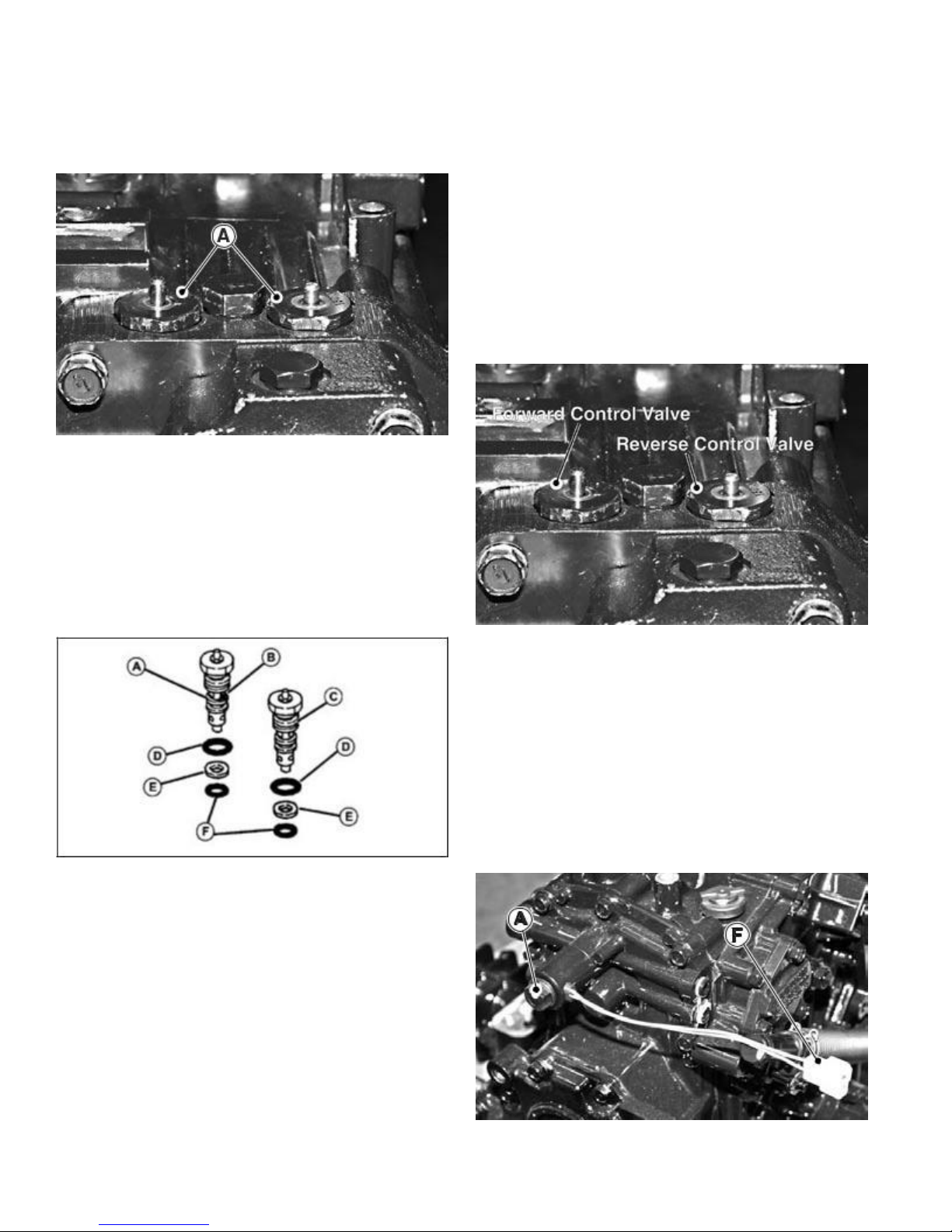
Fig. 4, Control Valves
1. Remove directional control valves (A). (Fig. 4)
NOTE: Installation is done in the reverse order of removal.
• Tighten directional control valves to 35 N•m (26 lb-ft).
Disassembly, Inspection and Assembly:
Fig. 5, Control Valve Disassembly
A - Reverse Control Valve (with orifice)
B - Orifice
C - Forward Control Valve
D - O-ring
E - Backup Ring
F - O-ring
1. Disassemble parts from directional control valves.
2. Inspect O-rings and backup rings for damage.
3. Plunger pin must move freely.
4. Internal valve must move freely when valve is shaken.
5. Make sure orifice and all passages are free of
any obstruction.
6. Assemble parts.
IMPORTANT:
Avoid damage!
The reverse control
valve must be installed
in
the left port. The control
valve can
be identified
by a small
orifice drilled into
a land between the two sets of valve passageways.
Fig. 6, Control Valve Location
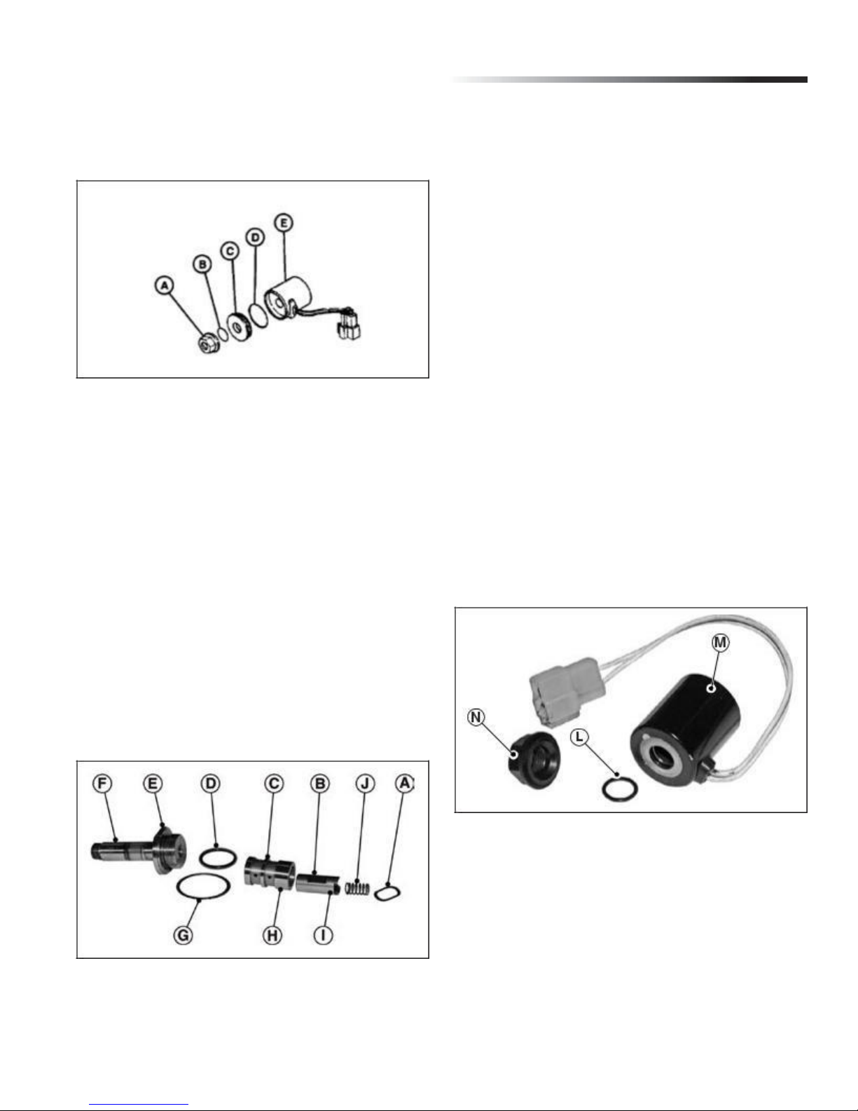
PTO Solenoid Valve
Removal and Installation:
IMPORTANT: Avoid damage! Do not bend, twist or
damage solenoid armature. Do not damage machined
sur-faces or sharp edges of spool or sleeve. PTO will
not function or will function erratically if spool, sleeve or
armature is dam-aged.
Fig. 7, Charge Pump Rotor
4
Tuff Torq K92 Hydrostatic Transaxle
1. Disconnect solenoid connector (F) from wiring harness.
(Fig. 7)
2. Remove nut (A) and O-ring (B). (Fig. 8)
Fig. 8, Solenoid Coil Disassembly
3. Remove solenoid cover (C), O-ring (D), and
solenoid coil (E). Note order and direction of valve
components for reassembly.
4. Remove solenoid armature assembly. (Fig. 9)
5. Carefully remove valve components from PTO cover.
NOTE: Check bottom of bore for “wave” washer.
6. Clean and inspect parts for damage. Replace if
neces-sary.
7. Place wave washer in case cover.
Disassembly, Inspection and Assembly:
NOTE: Sleeve and spool must be replaced as a set.
IMPORTANT: Avoid damage! Be sure large land (H) on sleeve
and oil hole in spool are facing away from PTO case cover.
Fig. 9, PTO Solenoid Armature Disassembly
A - Wave Washer
B - Spool
C - Sleeve
D - O-ring
E - Flats
F - Solenoid Armature
G - Gasket
H - Large Land on Sleeve
I - Oil Hole
J - Spring
1. Disassemble PTO solenoid valve.
2. Inspect parts for wear or damage.
3. Install spool into sleeve so the end with the oil hole
is toward the large land on the sleeve.
4. Place spring into recess in end of spool.
5. Install sleeve assembly so smaller lands go into the
PTO cover first.
6. Install gasket and O-ring.
Fig. 10, Solenoid Coil
7. Tighten solenoid armature to 22 N•m (195 lb-in.).
8. Slide solenoid coil (M) onto solenoid armature.
Install O-ring (L) and plastic nut (N) (do not tighten
plastic nut at this time.) (Fig. 10)
5
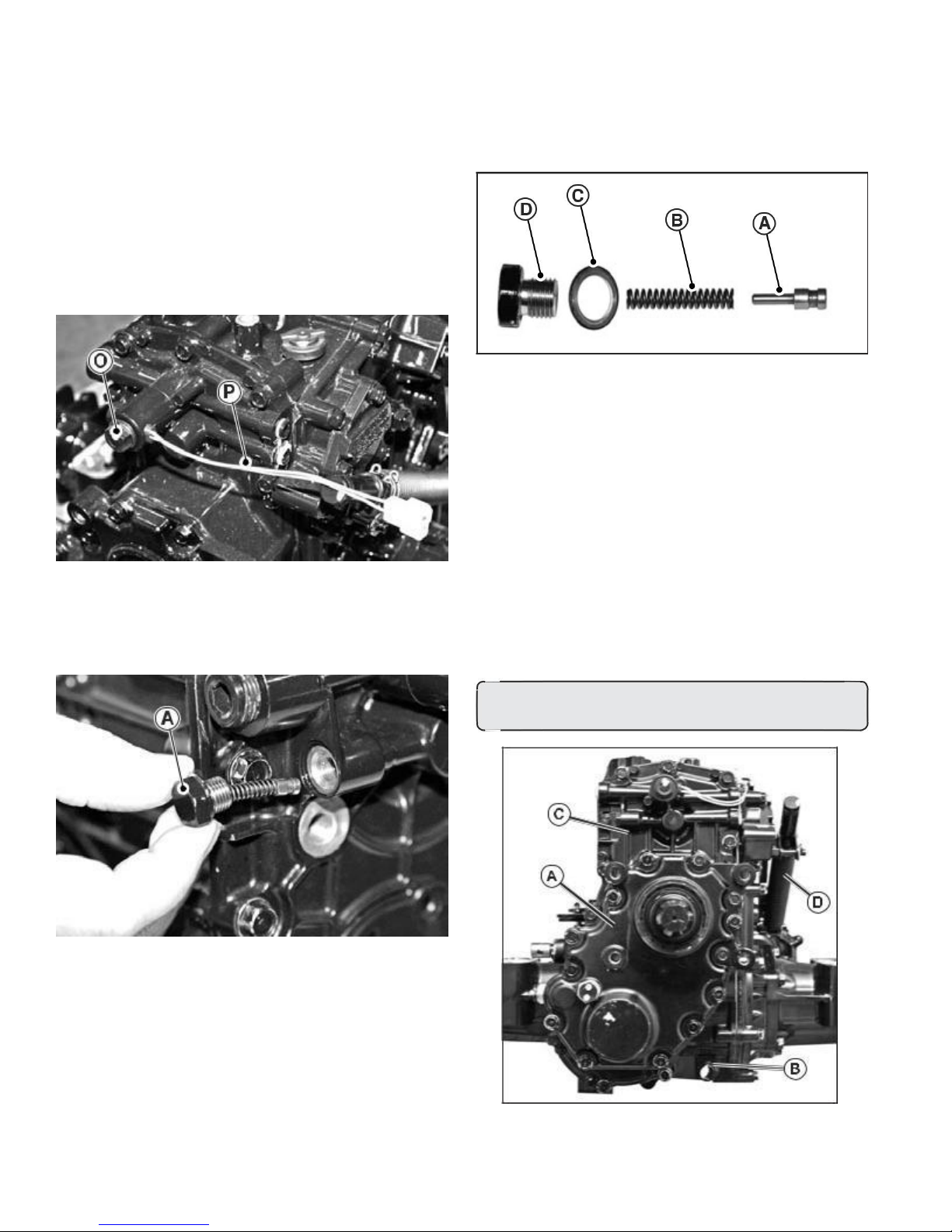
9. Position solenoid coil wire leads (P) to the right
and approximately 45° above horizontal.
IMPORTANT: Avoid damage! When tightening
plastic nut be sure to tighten nut to exact
specifications. Nut has a very low torque. Any
overtightening will damage the armature coil.
10. Tighten plastic nut (O) to 4.9 N•m (43 lb-in.). (Fig. 11)
Fig. 11, PTO Electrical Solenoid
PTO Relief Valve Removal and Installation
Fig. 12, Relief Valve Plug
1. Remove relief valve plug. (Fig. 12)
2. Install relief valve plug (A) and tighten to 25 N•m
(19 lbft).
PTO Relief Valve Disassembly, Inspection
and Assembly
Fig. 13, Relief Valve Assembly
1. Disassemble PTO relief valve. (Fig. 13)
2. Check relief valve plunger and bore for scoring,
nicks or burrs. Replace if necessary.
3. Install spring (B), gasket (C), relief valve plunger (A),
and plug (D) in PTO cover. (Fig. 13)
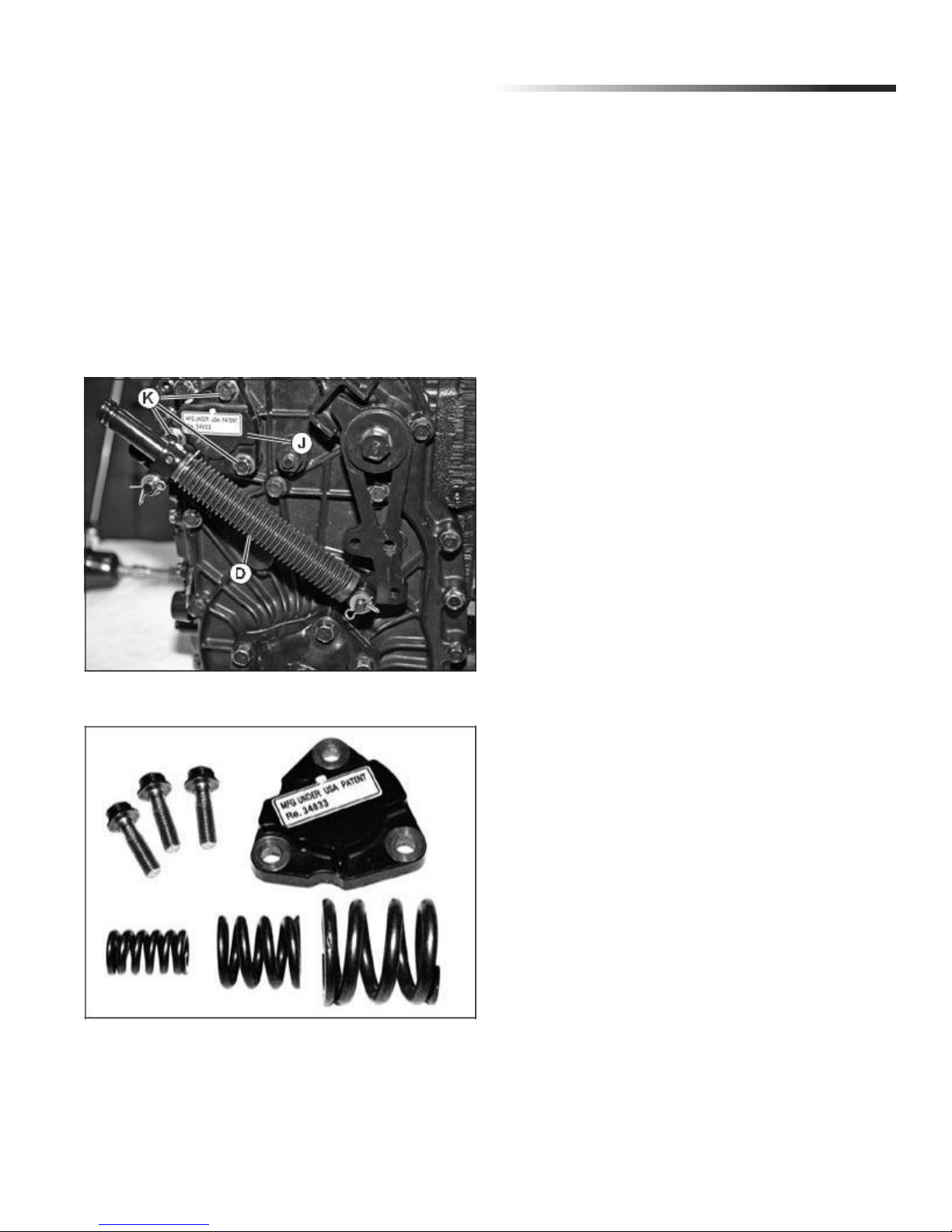
PTO Brake Removal and Installation
NOTE: Approximate capacity of hydrostatic power train
is 7.5L (7.9 qt) for 2WD and 7.8L (8.2 qt) for 4WD and
9.0L (9.5 qt) for 4WD w/rear PTO.
CAUTION: Avoid Injury! Allow transaxle to cool before
drain-ing fluid. Hot fluid can cause serious burns.
Fig. 14, Transaxle/Rear PTO Cover
6
Tuff Torq K92 Hydrostatic Transaxle
1. Remove plug (B) to drain oil from transaxle. (Fig. 14)
NOTE: If rear PTO is installed, remove necessary rear
PTO components before rear transaxle cover removal.
(See “Rear PTO Removal and Installation” on page 12.)
2. Remove optional rear PTO (A), if installed. (See “Rear
PTO Removal and Installation” on page 12.) (Fig. 14)
3. Remove rear transaxle cover (C). (Fig. 14)
4. Remove control arm damper (D), (Fig. 14-15), to gain
access to (3) cap screws (K), (Fig. 15), holding PTO brake
cover (J), (Fig. 15), to transaxle side cover. (See “Control
Arm and Damper Removal and Installation” on page 1.)
Fig. 15, PTO Brake Cover Removal
Fig. 16, PTO Brake Cover Kit
NOTE: Installation is done in the reverse order of diassembly.
7
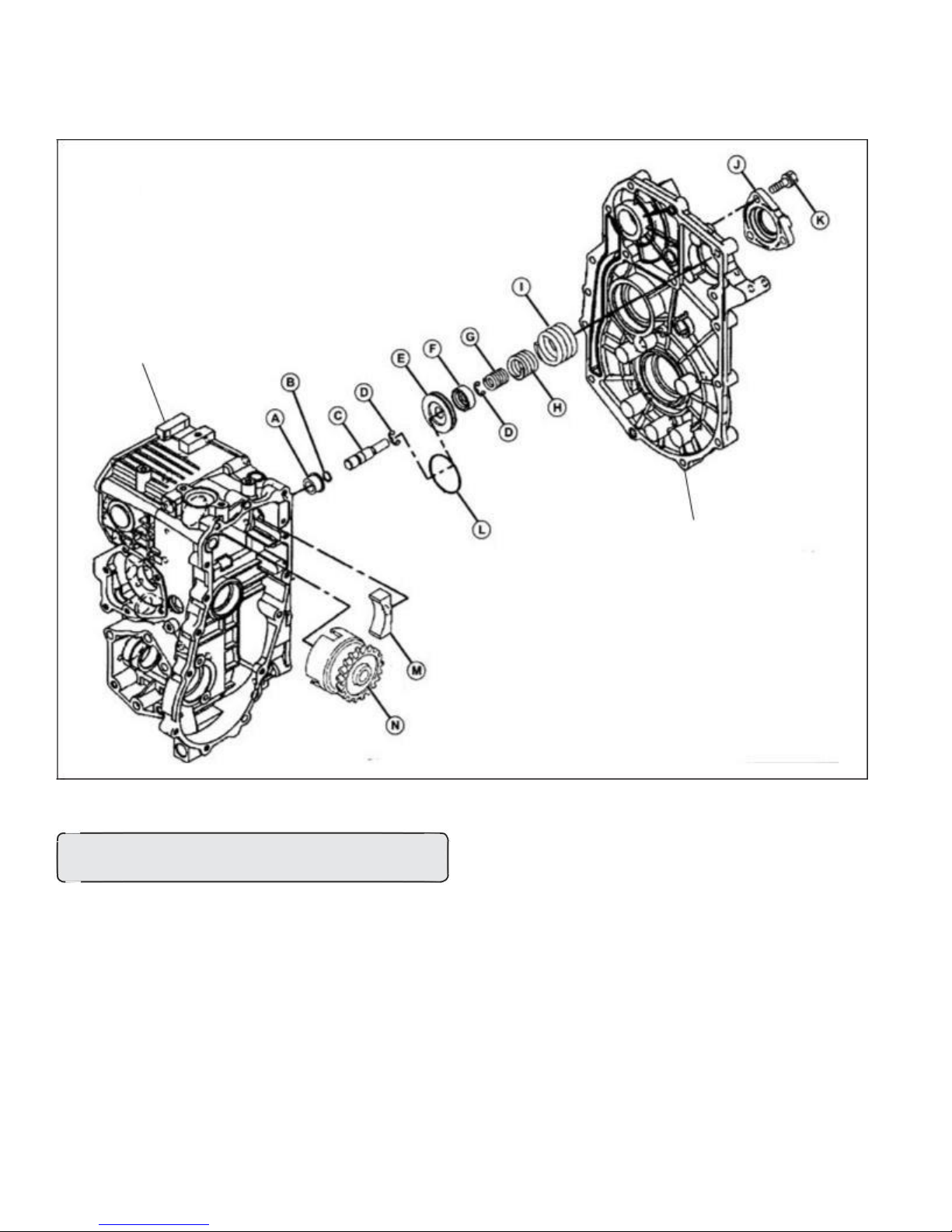
PTO Brake Disassembly, Inspection and Assembly (Fig. 17)
Transaxle Case
Side Cover
Fig. 17, PTO Brake Disassembly
CAUTION: Avoid Injury! PTO brake cover is spring loaded.
Remove cap screws evenly to release spring force.
A - Collar, Brake Pin
B - O-ring
C - Pin, PTO Brake
D - Snap Ring (2 used)
E - Piston
F - Stopper
G - Spring, Inner
H - Spring, Middle
I - Spring, Outer
J - Cover
K - Cap Screw (3 used)
8
Tuff Torq K92 Hydrostatic Transaxle
L - O-ring
M - PTO Brake Shoe
N - PTO Clutch Assembly
1. Carefully pull piston assembly from case using a
pliers. Do not damage pin. (Fig. 17)
2. Remove PTO clutch assembly (N) and brake
shoe (M) together.
NOTE: PTO brake pin, piston, springs, and O-rings,
etc., (parts C thru I), must be replaced as a set.
3. Check pin and piston for burrs, scoring or wear.
4. Replace brake shoe if grooves in shoe contact
surface are not visible.
5. Inspect O-rings for cuts or damage.
6. Inspect springs for cracks or damage.
7. Apply petroleum jelly to O-rings and seal on end of
PTO clutch shaft.
8. Install piston assembly and clutch assembly.
9. Clean mating surface of side cover and transaxle
case. Be sure threaded holes are clean.
10. Apply a bead of silicon sealant to cover mating of
sur-face.
IMPORTANT: Avoid damage! Be sure side cover is
aligned with transaxle case and installed within 3 mm
(1/8 in.) of case before tightening cap screws. Major
damage can occur to cover and/or case if cover is not
installed properly before tightening cap screws.
Transaxle Cover Cap Screw Torque Specifications:
• Used Transaxle Case . . . . . . . . . . . . . . 25 N•m (18 lb-ft)
• New Transaxle Case . . . . . . . . . . . . . . . 30 N•m (22 lb-ft)
NOTE: Remove necessary rear PTO components
before rear transaxle cover removal. (See “Rear PTO
Removal and Instal-lation” on page 14.)
2. Remove optional rear PTO (A), if installed. (See “Rear
PTO Removal and Installation” on page 14.) (Fig. 18)
3. Remove rear transaxle cover (C). (Fig. 18)
Fig. 18, Transaxle Cover
4. Remove PTO clutch assembly (A). (Fig. 19)
5. Remove PTO idler gear assembly (N). (Fig. 19)
6. Remove PTO gear (K). (Fig. 19)
7. Left axle must be removed to remove PTO output
shaft assembly (L), (See “Rear Axle Assembly
Removal and Installation” on page 41.)
PTO Drive Train (Mid-PTO) Removal and
Installation
NOTE: Approximate capacity of hydrostatic power train
is 7.5L (7.9 qt) for 2WD and 7.8L (8.2 qt) for 4WD and
9.0L (9.5 qt) for 4WD w/rear PTO.
Removing:
CAUTION: Avoid Injury! Allow transaxle to cool before
drain-ing fluid. Hot fluid can cause serious burns.
1. Remove plug (B) to drain oil from transaxle. (Fig. 18)
9
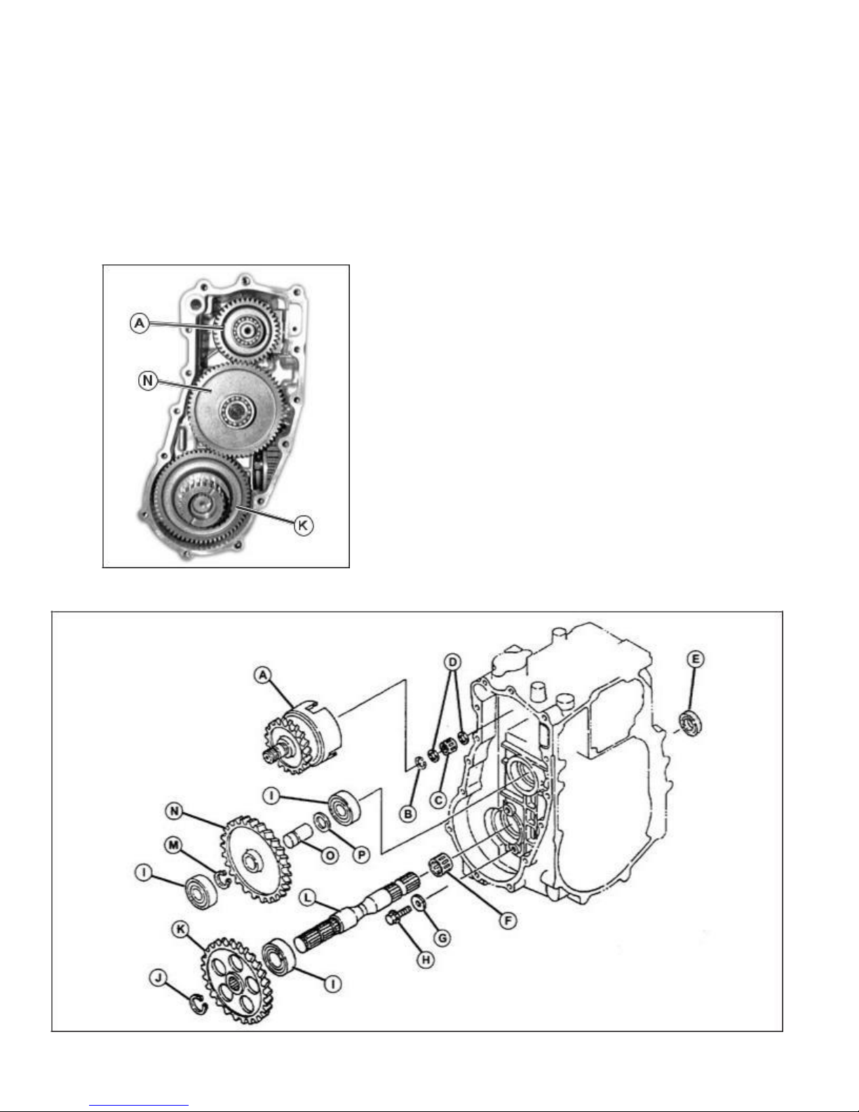
PTO Drive Train (Mid-PTO) Removal and Installation (continued)
8. Inspect ball bearings and needle bearing for
smooth rotation.
NOTE: Idler gear (N) and shaft (O) must be replaced
as a set. (Fig. 19)
9. Inspect gears and splines for missing or chipped teeth,
wear or damage. Replace parts if necessary.
A - PTO Clutch Assembly
B - Snap Ring
C - Needle Bearing
D - Washer
E - Seal
F - Needle Bearing
G - Washer
H - Cap Screw
I - Ball Bearing
J - Snap Ring
K - Mid-Mount PTO Gear
L - PTO Output Shaft
M - Snap Ring
N - PTO Idler Gear
O - PTO Idler Shaft
P - Washer
Fig. 19, Rear PTO Cover Removed
Fig. 20, PTO Drive Train (Mid-PTO) Disassembly
10
 Loading...