

Tuff stuff TBU-335 Smith-Half Cage Series, THC-43C Smith-Half Cage Series, TSM-45L Smith-Half Cage Series Assembly Instruction Manual
Page 1
ASSEMBLY INSTRUCTIONS
TABLE OF CONTENTS:
Introduction
Pg. 1
Safety Precautions
Pg. 2
Assembly Instructions
Pg. 3 - Pg. 6
TBU-335 Exploded View Diagram
Pg. 7
THC-43C Exploded View Diagram
Pg. 8
TSM-45L Exploded View Diagram
Pg. 9
Maintenance
Pg. 10
Warranty
Back Page
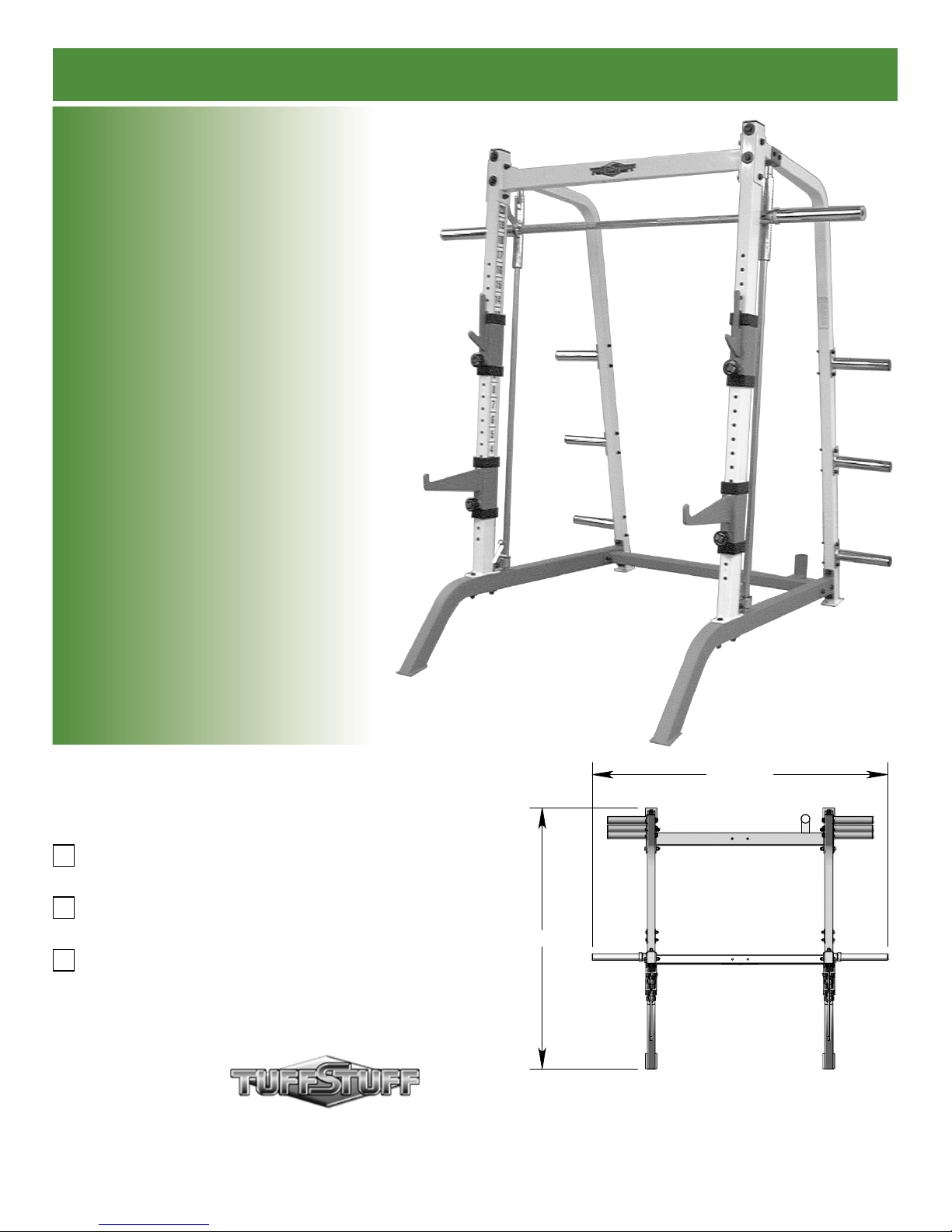
Smith-Half Cage Series
Includes Assembly for:
TBU-335
Base Unit
THC-43C
Half Cage Conversion Kit
TSM-45L
Smith Linear Bearing Press Kit
Revision Date 04-03-03
76 1/2"
67 3/4"
America’s Premium Exercise Equipment
L 67 3/4" W 76 1/2" H 82"
Page 2
bout the Smith-Half Cage Series
o
-
y
l
s
r
t
y
y
t
y
a
e
y
e
s
s
ongratulations on your new purchase of the Smith-Half Cage
eries. This gym is capable of a variety of different exercises, as-
ell-as, smooth and user-friendly adjustment features. In addition,
his gym has been designed to meet the needs and performance
equirements for a suitable home exercise machine. We hope you
re completely satisfi ed with this product and wish you many years
f enjoyment.
uff Stuff Equipment
his Tuffstuff product has been built to precise quality standards
nd has been carefully packaged to ensure that damage will
ot occur during shipment. The Home Lifetime Warranty and
ignature indicating fi nal inspection has been conducted by our line
oreman, is an expression of our confi dence in the completeness,
he materials, and workmanship of this product.
arranty
EE A COPY OF WARRANTY ON BACK PAGE.
egistration Card
o avoid unnecessary delays in warranty service and to insure that
permanent record of your purchase is on fi le with our factory, be
ure to complete the warranty registration card and send it to Task
ndustries today.
pecifi cations
About the Icons
The icons displayed in this Assembly Instructions are used t
facilitate the correct assembly and safe use of this Product, as
well-as to prevent injury to yourself or anyone else.
Note provides information necessary to properl
complete a procedure or information which wil
make the procedure easier to understand.
Caution indicates a potentially hazardou
situation, which, if not avoided, may result in mino
or moderate injury. It may also be used to aler
against unsafe practices.
Loosely Fasten provides a instruction to loosel
fasten (ex: hand tighten) a hardware assembl
only. This instruction is intended for the alignmen
of hardware components during the assembl
process.
Fully Fasten provides a instruction to fully fasten
(ex: completely tighten) a hardware assembly.
TBU-335 THC-43C TSM-45L
. Maximum Wt. Capacity N/A 400 Lbs. 300 Lbs.
. Total Machine Weight 220 Lbs. 40 Lbs. 80 Lbs.
. Footprint (LWH) - See Front Cover
rior to the Assembly of the Smith-Half Series
. We advise you to consult your local Tuff Stuff retailer if you
should have a question or problem regarding the proper
assembly of this unit.
. Consider the complete surface area of the Smith-Half Cage
Series. Use the overhead view located on the front page for
designing your layout before assembling. Once the Smith-Half
Cage Series has been fully assembled it will be heavy and
diffi cult to move, therefore you should assemble the unit in the
area where it is to be used upon completion.
. It is recommended that another person assist you with the
assembly of this unit.
. Neatly organize and identify all parts according to the Parts List
and the Exploded View Diagrams on pages 7 - 9.
ool Requirements
1. One 3/4” combination wrench
2. One 9/16” combination wrench
3. One ratchet
4. One 3/4” socket
5. One 9/16” socket
6. One rubber mallet
7. Windex or household glass cleaner
8. One can silicone spray/ tefl on spray lubricant
9. Measuring tape
0. Utility knife
Assembly Notes
1. Read and follow each step of this Assembly Instruction Manu
in sequence. Do not skip ahead, as it will result in an imprope
assembly or in having to disassemble parts later.
2. During the assembly of this unit you will be instructed to leav
some Hex Head Cap Screws loosely fastened. Naturally, the
will be fully fastened later in the assembly process. This is don
to prevent any diffi culty with alignment of some parts during thi
assembly.
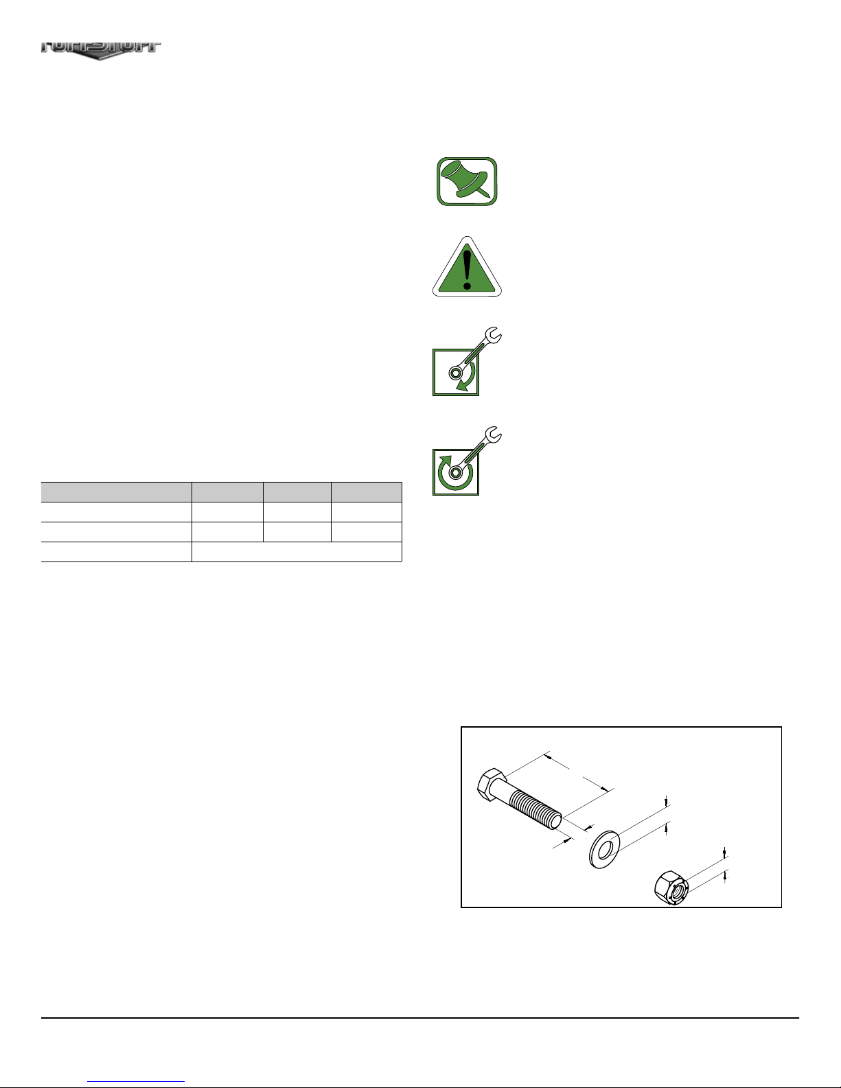
Hardware Measurement Diagram
SCREWfiLENGHT
WASHERfiDIAMETER
SCREWfiWIDTH
Note: Due to continuing product improvements, specifi cations and designs are subject to change
without notice.
NUTfiDIAMETER
1
Smith-Half Cage Serie
Page 3
a
2
3
4
5
6
7
8
9
Safety Precautions
n
e
b
a
h
o
afety First
egardless of how enthusiastic you may be about getting on your equipment and
xercising, take the time to ensure that your safety is not jeopardized. A moment’s
ck of attention can result in an accident, as can failure to observe certain simple
afety precautions.
1. Read, study and understand the Assembly Instructions and all the warning
labels on this product. Furthermore, it is recommended to familiarize yourself
and others with the proper operation and workout recommendations for this
Lock
Tuff Stuff product prior to use. Some of this information can be obtained in this
Assembly Instructions, as-well-as from your local Tuff Stuff Retailer.
. It is imperative that you retain this Assembly Instructions and be sure all warning
labels are legible and intact. Replacement of the Assembly Instructions and
labels are available from your local Tuff Stuff Retailer.
13
. Consult with your physician before beginning any exercise program.
4
Unlock
15
. Use proper discretion when children are present.
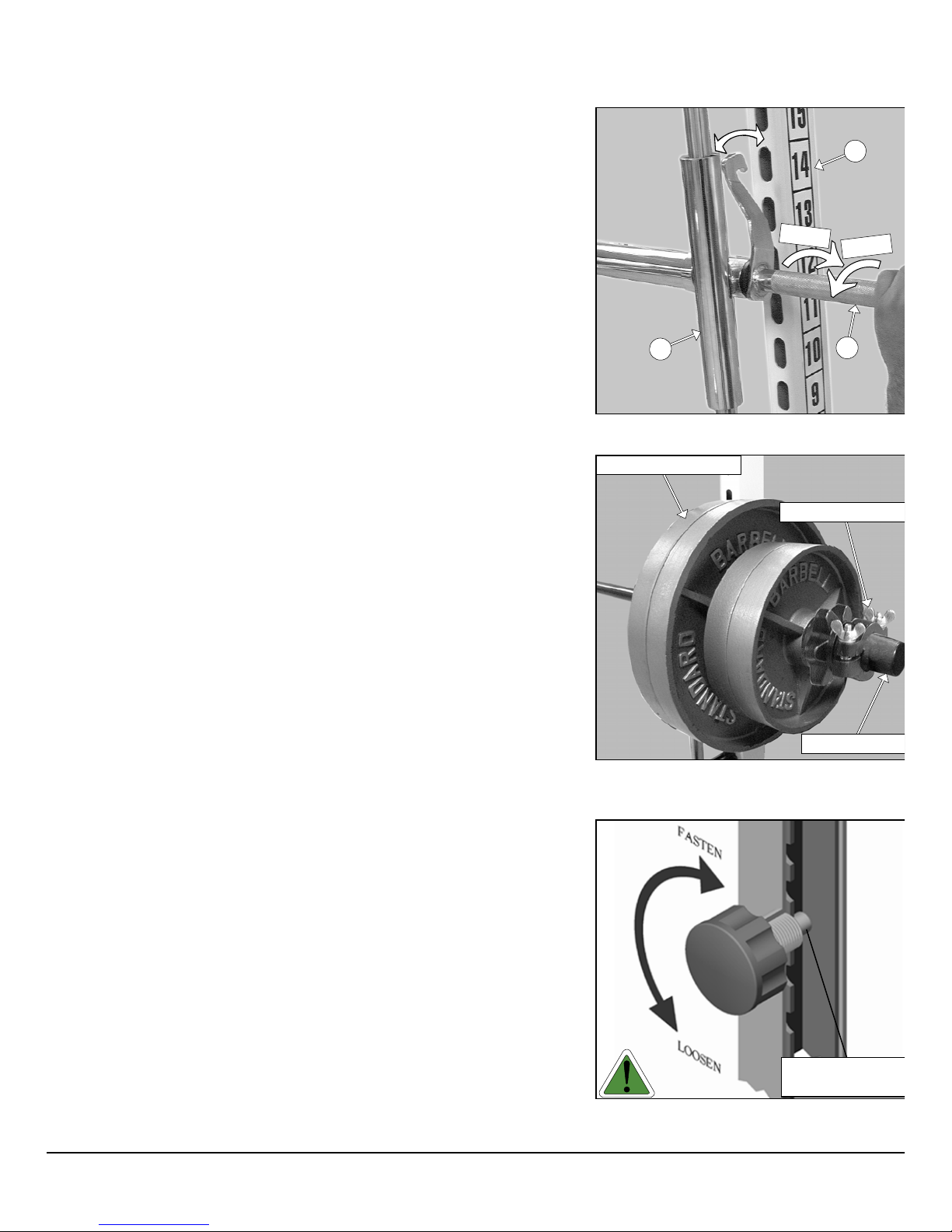
Fig. A Illustration above depicts the Press B
(#15) locking mechanism.
. Keep hands, limbs, loose clothing and long hair well out of the way of moving
parts.
. Do not attempt to lift more weight than you can control safely.
Barbell Weight Plates
Olympic Bar Colla
. Inspect the Smith-Half Cage for any sign of wear on parts, hardware becoming
loose or cracks on welds. If a Problem is found do not use or allow the
machine to be used until defective part is repaired or replaced.
. The Press Bar (#15) has a swivel locking mechanism that allows you to safely
lock out the Press Bar (#15) at virtually any setting. See Fig. A.
. The Safety Spotter Hooks (#11, #12) prevent the bar from being lowered
below desired point and avoid getting crushed under the Press Bar (#15) if the
weight is too heavy to control. Use the Decal-numbers 1-20 (#64) on the Front
Uprights (#4) to ensure that the Safety Spotter Hooks (#11,#12) are set to an
equal adjustment setting (same height).
10. Before you add weight plates to the Press Bar (#15), you should fi rst set-up the
Safety Spotter Hooks (#11,#12) for the desired exercise. It is recommended
that you test the desired setting without weight plates on the Press Bar (#15)
to make sure the Safety Spotter Hooks (#11,#12) are on the appropriate
exercise setting.
Weight Prong
Fig. B Caution: Use collars to prevent the weig
plates from falling off the Olympic Adaptors (#7)
the Press Bar (#15).
11. If you are adding or storing weight plates on the Olympic Adapters (#7) or the
Press Bar (#15), do not over-load them. Allow enough space to put a weight
collar into place. See Fig. B
12. Do not drop heavy weight on the Safety Spotter Brackets (#10), as it can
result in damage to the equipment.
13. Pay special attention to the Turn/ Pull Pins w/Knob (#138) located on the Bar
Holders (#18) and the Bar Safety Spotters (#17). Be sure they are fully en-
gaged into the selectorized holes of the Front Uprights (#4). Refer to Fig. C
for further illustration.
Turn/Pull Pin w/Kno
Fig. C Caution: Check that all Turn/Pull Pi
w/Knob (#138) to be fully engaged into the select
holes of the Front Uprights (#4).
mith-Half Cage Series 2
Fully Engaged
Page 4
s
o
m
m
u
n
n
BU-335 TBU-335
3
1
2
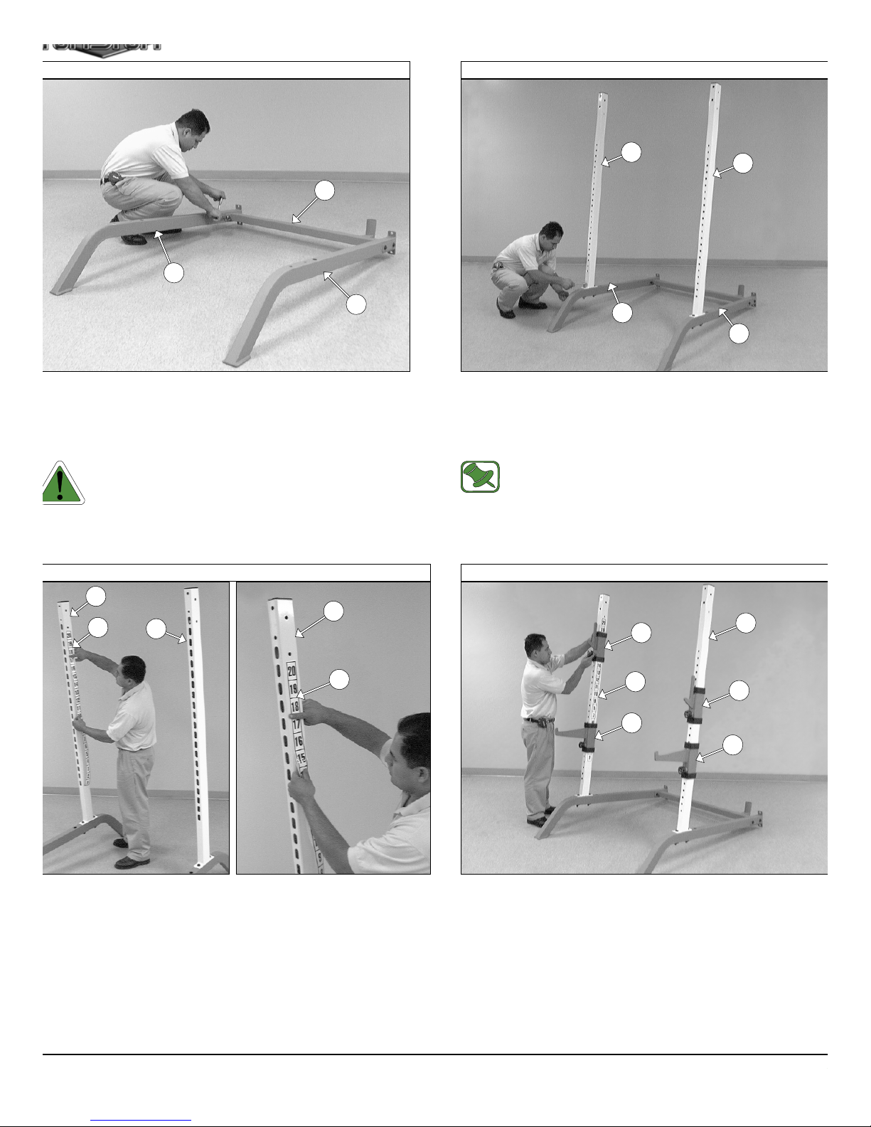
IG. 1 Locate the two Bottom Frames (#1, #2) and the Bottom
ross Brace (#3) and attach them, in the position as shown above,
sing four Hex Head Cap Screws 1/2-13 X 3 1/2 (#77), four Flat
ashers SAE 1/2” (#70), and two Nylon Insert Lock Nuts 1/2-13
101).
Caution: It is strongly recommended to use another person
in assisting with the following assembly.
4
1
4
2
FIG. 2 Attach the two Front Uprights (#4) to the two Botto
Frames (#1, #2), in the position as shown above, and secure the
into place using four Hex Head Cap Screws 1/2-13 X 4 1/4 (#78), fo
Flat Washers SAE 1/2” (#70), four Flat Washers 1/2 X 1 3/4 (#68), an
four Nylon Insert Lock Nuts 1/2-13 (#101).
Note: Make sure to assemble the Front Uprights (#4) with
the oval hole pattern towards to the back of the Unit.
BU-335 THC-43C
4
4
64
IG. 3 Next, attach the Decal Numbers 1-20 (#64) to both Front
prights (#4). Center the number 20 with the second adjustment hole of
e Front Upright (#4). A great way to make sure you don’t trap any air
ubbles under the decal is by using the wedge method. Press the side of
ur index fi nger against the decal and as you slide your fi nger down, with
e other hand, slowly remove the rest of the backing off the decal.
4
64
FIG. 4 Next, slide the Bar Safety Spotters (#17) onto the Fro
Uprights (#4). Then, slide the Bar Holders (#18) onto the Fro
Uprights (#4) as shown above.
17
18
4
4
18
17
3
Smith-Half Cage Serie
Page 5

a
i
SM-45L TSM-45L
Assembly Instruction
9
1
9
2
IG. 5 Insert the Linear Shafts 1 X 70 (#9) into the receptacles of
e Bottom Frames (#1, #2).
11
10
9
10
12
9
44
FIG. 6 Insert the assembled Safety Spotter Brackets (#10) onto th
Linear Shafts (#9).
Caution: It is strongly recommended to use another person
assisting with the following assembly.
SM-45L TSM-45L
13
9
15
IG. 7 Align the Chrome Press Bar Housings (#13) with the
inear Shafts (#9) and carefully begin sliding the assembled Press
ar down onto the Linear Shafts (#9).
13
9
FIG. 8 Next, insert the Shaft Retainers (#14), in the position
shown above, to the Linear Shafts (#9).
14
14
15
9
9
Caution: It is strongly recommended to use another perso
in assisting with the following assembly.
mith-Half Cage Series 4
Page 6

w
/
2
s
n
e
2
r
o
BU-335 TBU-335
4
5
5
1
2
5
4
5
IG. 9 Affi x the two Rear Side Supports (#5) to the two Bottom
rames (#1, #2) using four Hex Head Cap Screws 1/2-13 X 3 1/2
77), eight Flat Washers SAE 1/2” (#70), and four Nylon Insert Lock
uts 1/2-13 (#101).
FIG. 10 Next, affi x the two Rear Side Supports (#5) to the t
Front Uprights (#4) using four Hex Head Cap Screws 1/2-13 X 4 1
(#78), four Flat Washers 1/2 X 1 3/4 (#68), four Flat Washers SAE 1/
(#70), and four Nylon Insert Lock Nuts 1/2-13 (#101).
Loosely Fasten: Do not completely fasten this hardware
assembly at this time, as it will be completely fastened later
in the assembly process.
SM-45L TBU-335
14
5
9
14
9
5
6
8
4
4
8
IG. 11 Secure the two Shaft Retainers (#14) along with the two
nfi ned Linear Shafts 1 X 70 (#9) to the Rear Side Frames (#5)
sing four Hex Head Cap Screws 3/8-16 X 3 (#85), eight Flat Washers
AE 3/8” (#71), and four Nylon Insert Lock Nuts 3/8-16 (#99).
5
FIG. 12 Attach the Top Cross Brace (#6) to the top of both Fro
Uprights (#4) using two Reinforcement Plates 3 X 7 (#8), four H
Head Cap Screws 1/2-13 X 3 1/2 (#77), eight Flat Washers SAE 1/
(#70), and four Nylon Insert Lock Nuts 1/2-13 (#101).
Fully Fasten: Proceed to align and fully fasten this hardwa
assembly and all of the previous assemblies that were le
loosely fastened.
Smith-Half Cage Serie
Page 7

/
IG. 3
Assembly Instruction
5
7
7
IG. 13 Using a rubber mallet, insert one Plastic Insert Cap 1 7/8”
d. (#109) into the tube-end of each one of the Olympic Adapters
5
7
109
7
7
FIG. 14 Picture of the assembled TBU-335 Base Unit with the
THC-43C Half Cage Conversion Kit.
/Plate (#7). Next, attach the six Olympic Adaptors w/Plate (#7) to
e two Rear Side Frames (#5) using twelve Hex Head Cap Screws
8-16 X 3 (#85), twenty-four Flat Washers SAE 3/8” (#71), and twelve
ylon Insert Lock Nuts 3/8-16 (#99).
IG. 15 Picture of the assembled TBU-335 Base Unit with the
TSM-45L Smith Linear Bearing Press System Kit.
FIG. 16 Picture of the assembled TBU-335 Base Unit with the
THC-43C Half Cage Conversion Kit and the
TSM-45L Smith Linear Bearing Press System Kit.
mith-Half Cage Series 6
Page 8

t
t
y
2
4
2
2
2
0
s
TBU-335 Exploded View Diagram
7
0
78
68
78
70
68
68
4
70
101
101
70
68
78
70
112
77
70
101
5
70
3
70
70
101
70
71
101
101
63
71
101
99
77
70
70
6
101
70
101
101
68
78
70
70
68
64
78
70
78
70
112
8
70
70
101
70
101
101
70
70
77
59
99
5
71
71
70
70
77
70
71
85
7
71
85
109
101
70
64
109
85
71
7
85
71
70
101
70
70
101
1
70
8
77
68
101
68
70
70
101
2
OLOR CHART
RAY= SUB-ASSEMBLY PARTS
LACK= HARDWARE
TBU-335
Parts Lis
em Description Part No. Qty Item Description Part No. Qt
1 RIGHT SIDE BOTTOM FRAME UP2205 1 68 FLAT WASHER 1/2 X 1 3/4 BNH0241 8
2 LEFT SIDE BOTTOM FRAME UP2206 1 70 FLAT WASHER SAE 1/2" BNH0238 3
3 BOTTOM CROSS BRACE UP2203 1 71 FLAT WASHER SAE 3/8" BNH0239 2
4 FRONT UPRIGHT UP2207 2 77 HEX HEAD CAP SCREW GR-5 B/O 1/2-13 X 3 1/2 BNH0263 1
5 REAR SIDE SUPPORT UP2204 2 78 HEX HEAD CAP SCREW GR-5 B/O 1/2-13 X 4 1/4 BNH0291 8
6 TOP CROSS BRACE UP0519 1 85 HEX HEAD CAP SCREW GR-5 B/O 3/8-16 X 3 BNH0282 1
7 OLYMPIC ADAPTER W/PLATE UP2202 6 99 NYLON INSERT LOCK NUT 3/8-16 BNH0214 1
8 REINFORCEMENT PLATE 3 X 7 UP0543 2 101 NYLON INSERT LOCK NUT 1/2-13 BNH0212 2
59 DECAL-CAUTION 1 3/4 X 5 1/2 BNH0126 1 109 PLASTIC INSERT CAP 1 7/8" RD. BNH0003 6
63 DECAL-LARGE TUFFSTUFF LOGO BNH0360 1 112 PLASTIC INSERT CAP 2 X 3 BNH0052 2
64 DECAL-NUMBERS 1-20 (TEFLON) BNH1304 2
TBU-335_Rev2
7
Smith-Half Cage Serie
Page 9

138
t
y
C
G
THC-43C Exploded View Diagram
116
18
116
67
116
18
17
116
138
67
17
OLOR CHART
RAY= SUB-ASSEMBLY PARTS
BLACK= HARDWARE
em Description Part No. Qty Item Description Part No. Qt
17 BAR SAFETY SPOTTER UP0520 2 116 PLASTIC TUBE GUIDE W/LIP 2 1/2 X 3 1/2 BNH0057 8
18 BAR HOLDER UP0521 2 138 TURN/PULL PIN W/KNOB AND LOCK BNH0989 4
67 FLAT PHILLIPS MACHINE SCREW 8-32 X 1/4 BNH0408 4
THC-43C_Rev2
THC-43C
Parts Lis
mith-Half Cage Series 8
Page 10

y
s
71
85
14
71
71
119
92
71
9
99
TSM-45L Exploded View Diagram
99
71
71
14
119
71
71
85
9
134
92
97
92
13
70
134
120
54
119
97
70
75
TSM-45L
16
125
90
13
15
5
70
1
97
OLOR CHART
RAY= SUB-ASSEMBLY PARTS
LACK= HARDWARE
92
119
97
10
70
98
106
120
98
12
Parts List
Item Description Part No. Qty Item Description Part No. Qt
9 LINEAR SHAFT 1 X 70 UP0553 285HEX HEAD CAP SCREW GR-5 B/O 3/8-16 X 3 BNH0282 4
10 SAFETY SPOTTER BRACKET UP0523 290HEX KEY M14 BNH1303 1
11 SAFETY HOOK RT UP0524 192LINEAR BEARING BNH0770 4
12 SAFETY HOOK LT UP0525 197NYLON BUSHING 1 X 1 1/2 BNH0531 4
13 CHROME PRESS BAR HOUSING UP0680 298NYLON INSERT JAM LOCK NUT 1/2-13 BNH0366 2
14 SHAFT RETAINER UP0528 299NYLON INSERT LOCK NUT 3/8-16 BNH0214 4
15 CHROME PRESS BAR W/HOOKS UP0678 1 106 NYLON WASHER 1 1/8 X 2 X 1/4 BNH0388 2
16 CHROME OLYMPIC ADAPTER UP0679 2 119 INTERNAL RETAINING RING 1 9/16" BNH0095 4
54 BRONZE BUSHING 1 1/8 X 1 11/32 X 3/4 BNH0735 2 120 INTERNAL RETAINING RING 1 7/16" BNH1308 4
70 FLAT WASHER SAE 1/2" BNH0238 4 125 SHOULDER BOLT 14 mm X 14 mm THREAD 1/2-13 BNH0426 2
71 FLAT WASHER SAE 3/8" BNH0239 8 134 STEEL NEEDLE-ROLLER BEARING (HMK-2830) BNH1307 4
75 HEX HEAD CAP SCREW GR-5 B/O 1/2-13 X 1 1/2 BNH0727 2
TSM-45L_Rev3
9
Smith-Half Cage Serie
Page 11

Maintenance
t
a
t
aintenance Information
1. Lubrication of all moving parts is essential to the
longevity and optimal performance of your SmithHalf Cage Series. Initial lubrication of some parts of
your gym has been done at the factory, but the Linear
Shafts must be lubricated at the time of assembly. We
recommend a light layer of tefl on grease.
Note: Do not use oil based lubricants as they will attract
dust, dirt and grime, and will eventually gum up and
erode bushings and sealed bearings.
2. Periodically check all moving parts for signs of wear or
damage. If there is a problem or replacement part is
necessary, STOP USING THE EQUIPMENT and immediately contact your local Tuff Stuff retailer or call our
Customer Service Department. Replace parts using
only genuine Tuff Stuff parts.
3. The unit should be wipe down with a damp cloth and
dried on a daily basis. The powder coat fi nish should
be polished with a good car wax on a weekly basis.
The chrome-plated surfaces should be polished with a
commercial grade or automotive type chrome polish on
a weekly basis.
4. Linear bearing systems are precision, high loa
components that require regular maintenance. Th
Linear Shafts must be wipe down weekly and lubricate
with a light layer of tefl on grease. Lack of care an
maintenance will result in corrosion of the Linear Shaf
causing the bearings to clogged and jammed.
5. When checking the bolts and nuts, be sure they are
fully fastened. If there is a bolt or nut that continuousl
loosens obtain a replacement through your local Tu
Stuff retailer or call our Customer Service Departmen
6. Check welds to be free of cracks.
7. Failure to perform routine maintenance could result i
personal injury and/or equipment damage.
mith-Half Cage Series 10
Page 12

DO NOT DISCARD THIS MANUAL
HOME LIFETIME WARRANTY
TuffStuff products are warranted to the retail purchaser to be free from defects in materials and workmanship.
TuffStuff exclusive Home Lifetime Warranty coverage extends for the life of the product while owned by the
original retail purchaser, and used only in a home or residential setting unless otherwise noted in the owner’s
manual.
This warranty does not cover:
1. TuffStuff products sold for and used in a commercial or institutional setting.
2. Any damage, failure or loss caused by accident, misuse, neglect, abuse, improper assembly, improper
maintenance, or failure to follow instructions or warnings in the owner’s manual and warning labels
posted on the machine.
3. Use of products in a manner for which they were not designed.
4. Original product that is altered, or the use of replacement parts and components of another manufacturer other than TuffStuff.
Limitations:
The foregoing shall constitute the sole remedy of the purchaser and the sole liability of TuffStuff with regard to
warranty, whether express or implied by operation of law or otherwise, including but not limited to any implied
warranties of merchantability or fitness. TuffStuff shall in no event be liable for incidental or consequential
losses, damages or expenses in connection with exercise products. TuffStuff’s liability hereunder is expressly
limited to the repairs or replacements of warranted defective parts.
Procedures:
Warranty service will be performed at TuffStuff’s facility in Pomona, California. TuffStuff will have the option of
either repair or replacement at no charge for any defective product. Purchaser is responsible for installation of
repaired or replaced parts and all transportation and insurance costs on returned or replaced equipment to and
from TuffStuff’s facility in Pomona.
This warranty gives you specific legal rights and you may also have other rights, which may vary from state to
state. Effective July 1, 2004.
This warranty is the final, complete and exclusive agreement of the parties with respect to the quality or performance of the equipment
and no action for breach of this written warranty or any implied warranty shall be commenced more than one (1) year after the accrual
of the cause of action. No modification of this warranty or waiver of its terms shall be binding on either party unless approved in
writing by an authorized representative of the party. Contact TuffStuff at 1325 E. Franklin Avenue, Pomona, California 91766, before
returning any defective equipment.
Note: Retain your sales receipt and be sure to mail in the warranty registration card to insure that a
permanent record of your purchase is on file with the factory and to avoid unnecessary delays in
warranty service.
TASK INDUSTRIES, INC.
1325 E. Franklin Ave., Pomona, CA 91766
Ph: 909-629-1600 Fax: 909-629-4967
E-mail: service@tuffstuff.net Net: www.tuffstuff.net
 Loading...