

Page 1
OWNER’ S MANUAL
TABLE OF CONTENTS:
Introduction - Pg. 1
Safety Precautions - Pg. 2
Assembly for TS-1000 - Pg. 3 - Pg. 23
Cable Adjustments - Pg. 22
Cable Mapping Diagrams
Pg. 24 - Pg. 29
Parts List - Pg. 31
Exploded View Diagram
Fold-Out Pg. 32
Adjustment Features - Pg. 33 - Pg. 34
Maintenance - Pg. 35
Warranty - Back Page
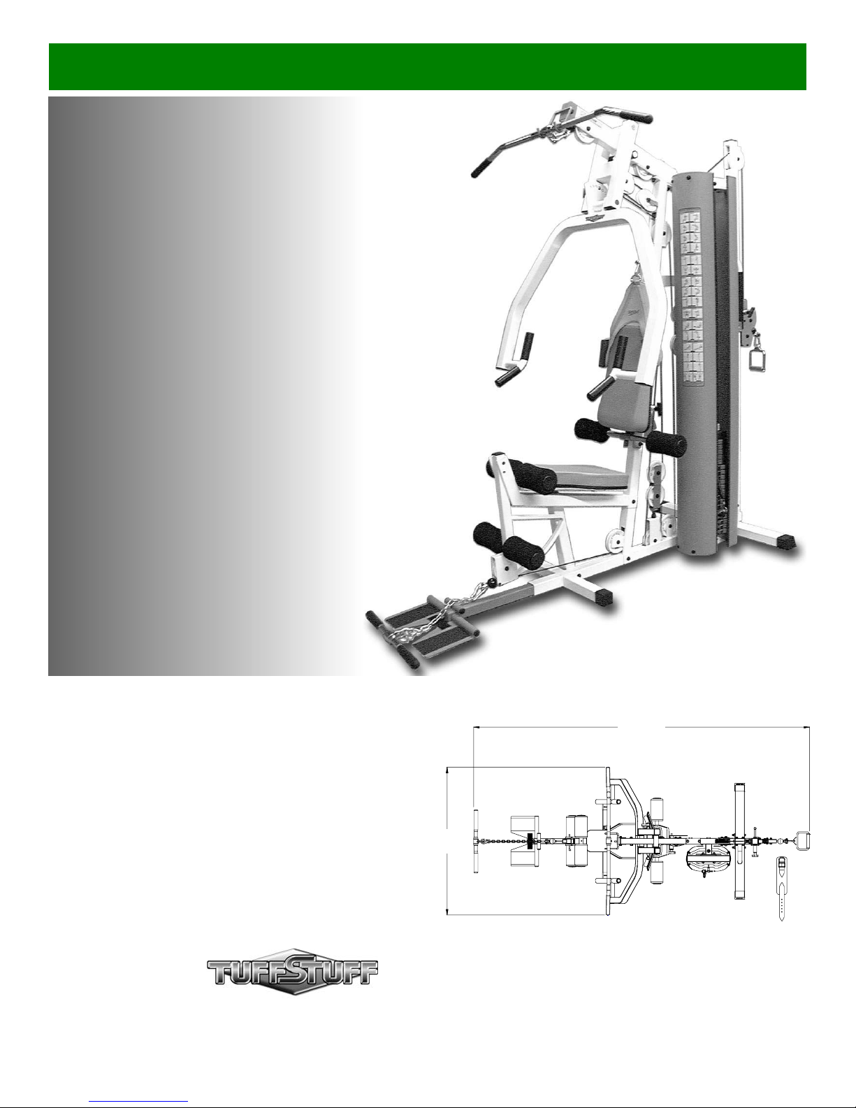
TS-1000
Home Gym w/Adjustable
High-Low Pulley System
Revision Date 10-16-01
108”
48”
America’s Premium Exercise Equipment
L 108” W 48” H 83”
Page 2
i
e
v
e
n
i
e
o
Int
roduction
g
o
y
-
r
t
m
N
y
y
t
y
bout the Home Gym (TS-1000)
ongratulations on your new purchase of the Home Gym (TS-
000). This gym is capable of a variety of different exercises, as
ell as, smooth and user-friendly adjustment features. In addition,
is gym has been designed to meet the needs and performance
quirements for a suitable home exercise machine. We hope you
re completely satisfied with this product and wish you many years
f enjoyment.
uff Stuff Equipment
his Tuffstuff product has been built to precise quality standards
nd has been carefully packaged to ensure that damage will not
ccur during shipment. The Home Lifetime Warranty and signature
dicating final inspection has been conducted by our line foreman,
an expression of our confidence in the completeness, the
aterials, and workmanship of this product.
arranty
EE A COPY OF WARRANTY ON BACK PAGE.
egistration Card
o avoid unnecessary delays in warranty service and to insure that
permanent record of your purchase is on file with our factory, be
ure to complete the warranty registration card and send it to Task
dustries today.
pecifications
.Maximum Wt. Capacity - 200 Lbs. Fixed
. Total Machine Weight - 475 Lbs.
. Footprint (LWH) - See Front Cover
About the Icons
The icons displayed in this Owner’s Manual are used to facilitat
the correct assembly and safe use of this Product, as-well-as t
prevent injury to yourself or anyone else.
Note provides information necessary to properl
complete a procedure or information which wil
NOTE:
CAUTION
LOOSELY FASTEN
FULLY FASTE
make the procedure easier to understand.
Caution indicates a potentially hazardous situa
tion, which, if not avoided, may result in minor o
moderate injury. It may also be used to aler
against unsafe practices.
Loosely Fasten provides a instruction to loosel
fasten (ex: hand tighten) a hardware assembl
only. This instruction is intended for the alignmen
of hardware components during the assembl
process.
Fully Fasten provides a instruction to fully fasten
(ex: completely tighten) a hardware assembly.
rior to the Assembly of the TS-1000
. We advise you to consult your local Tuff Stuff retailer if you
should have a question or problem regarding the proper
assembly of this Home Gym.
. Consider the complete surface area of the TS-1000. Use the
overhead view on the front page for designing your layout before
assembling. Once the TS-1000 has been fully assembled it will
be heavy and difficult to move, therefore you should assemble
the TS-1000 in the area where it is to be used upon completion.
. It is recommended that another person assist you with the
assembly this unit.
. Neatly organize and identify all parts according to the Parts List
on page 31 and the Exploded View Diagram on fold-out page 32.
Tool Requirements
1. One 9/16” combination wrench
2. One 3/4” combination wrench
3. One 7/8” combination wrench
4. One 1/2” combination wrench
5. Two 7/16” combination wrenches
6. One ratchet
7. One 9/16” socket
8. One 3/4” socket
9. One rubber mallet
0. External retaining-ring pliers
1. Windex or household glass cleaner
2. One can silicone spray/ teflon spray lubricant
3. Multi-purpose grease
4. Measuring tape
5. Utility knife
Assembly Notes
1. Read and follow each step of this Assembly Instruction Manual
sequence. Do not skip ahead, as it will result in an improp
assembly or in having to disassemble parts later.
2. During the assembly of this unit you will be instructed to lea
some Hex Head Cap Screws loosely fastened. Naturally, th
will be fully fastened later in the assembly process. This is do
to prevent any difficulty with alignment of some parts during th
assembly.
Hardware Measurement Diagram
Note: Due to continuing product improvements, specifications and designs are subject to chan
without notice.
Even though we have prepared this manual with extreme care, neither the publisher nor the auth
can accept responsibility for any errors in, or omission from, the information given.
1
TS-1000 Home Gym w/Adjustable High-Low Pulley Syste
Page 3
6
w
h
h
c
e
n
f
o
e
d
e
2
2
g
y
Safety Precautions
-
l
afety First
egardless of how enthusiastic you may be about getting on
our equipment and exercising, take the time to ensure that
our safety is not jeopardized. A moment’s lack of attention
an result in an accident, as can failure to observe certain
imple safety precautions.
. Read, study and understand the Owner’s Manual and all
the warning labels on this product. Furthermore, it is
recommended to familiarize yourself and others with the
proper operation and workout recommendations for this
Tuff Stuff product prior to use. Some of this information
can be obtained in this Owner’s Manual, as-well-as from
your local Tuff Stuff retailer.
. It is imperative that you retain this Owner’s Manual and be
sure all warning labels are legible and intact.
Replacement Owner’s Manuals and labels are available
from your local Tuff Stuff retailer.
. Consult with your physician before beginning any exercise
program.
. Use proper discretion when children are present.
5. Frayed or worn cables can be dangerous and may caus
injury. Periodically check these cables for any indicatio
of wear.
6. Keep hands, limbs, loose clothing and long hair well out o
the way of moving parts.
7. Do not attempt to lift more weight than you can contr
safely.
8. Inspect the Unit for any sign of wear on parts, hardwar
becoming loose or cracks on welds. If a problem is foun
do not use or allow the machine to be used until th
defective part is repaired or replaced.
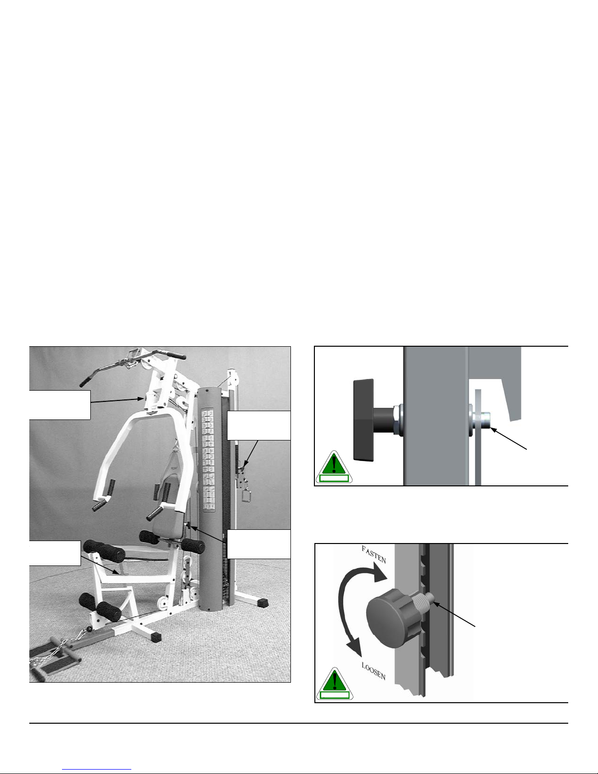
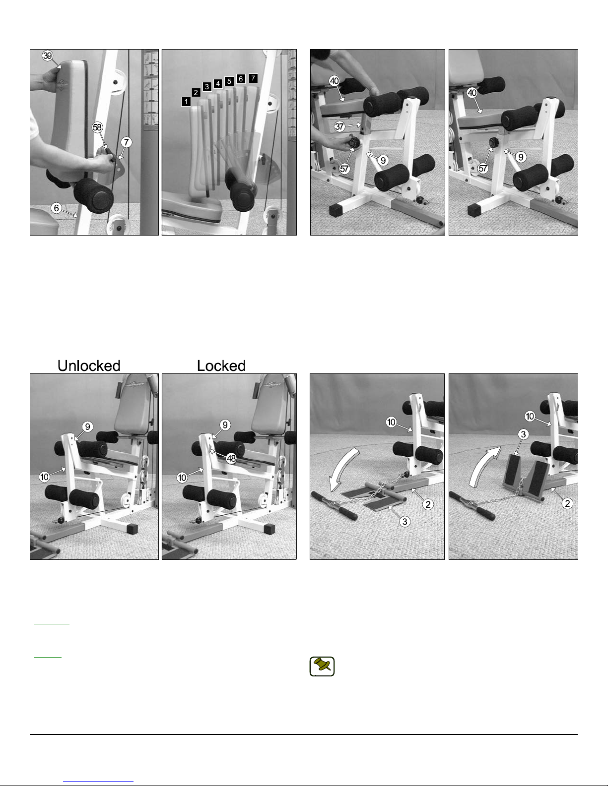
9. Pay special attention to the Push Pull Pins 1/2 X 3-1/
(#56) located on the Press Bar Selector Housing (#23)
and the High-Low Carriage (#14), the Push Pull Pins 1/
X5-5/8 (#58) located on the and the Front Upright (#6)
also the Turn/Pull Pin w/Knob (#57) located on the Le
Extension Bench Frame (#9). See Fig.1. Be sure the
are fully engaged into the selected holes. Refer to Fig. 2
3 for further illustration of this instruction.
ush Pull Pin
/2 X 3-1/2 (#56)
urn/Pull Pin
/Knob (#57)
Push Pull Pin
1/2 X 3-1/2 (#56)
Push Pull Pin
1/2 X 5-5/8 (#58)
Push Pull Pin
1/2 X 3-1/2
CAUTION
Fig. 2 Caution: Check that the two Push Pull Pins 1/2 X 3-1/2 (#5
located on the Press Bar Selector Housing (#23), and the High-Lo
Carriage (#14), also the Push Pull Pins 1/2 X 5-5/8 (#58) located on t
and the Front Upright (#6) are fully engaged into the selected holes of t
Press Bar (#23), High-Low Selectorized Upright (#13), and the Ba
Pad Bracket (#7).
Turn/Pull Pin w/Knob
Fully Engaged
Fully Engaged
ig. 1 Illustration above depicts the location of the Push Pull Pins 1/2” X
1/2 (#56), Push Pull Pins 1/2” X 5-5/8 (#58), and the Turn/Pull Pin w/
nob (#57) on this unit.
S-1000 Home Gym w/Adjustable High-Low Pulley System 2
CAUTION
Fig. 3 Caution: Check the Turn/Pull Pin w/Knob (#57) to be ful
engaged into the selected hole of the Adjustable Seat Frame (#37).
Page 4
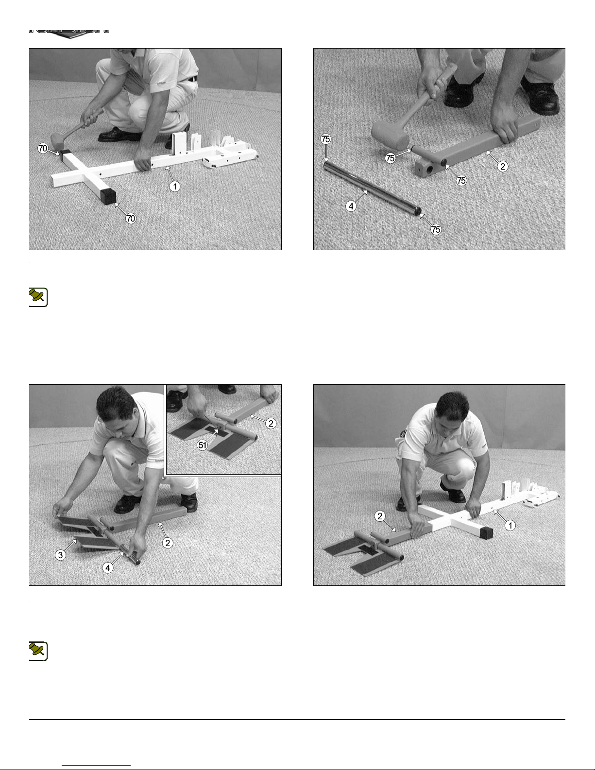
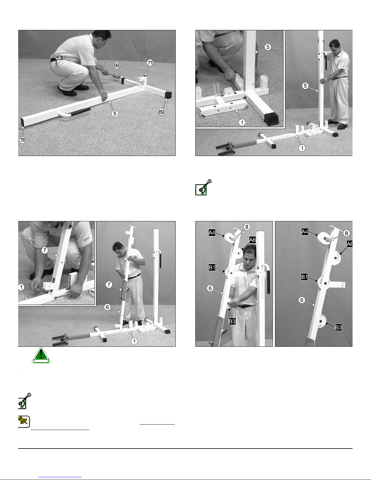
IG. 4 On a flat surface, lay the Base Frame (#1) down and insert two
1
m
lastic End Caps w/Groove 2” Sq. (#70) onto the tube-ends of the Base
rame (#1), as shown above.
Note: When positioning the Base Frame (#1) consider the
complete area surface of the TS-1000. Use the overhead view on
NOTE:
the cover page for designing your layout before assembling.
FIG. 5 Next, using a rubber mallet, insert four Plastic Insert Caps
Rd. (#75) into the four tube-ends of the Low Row Stabilizer (#2) and th
Foot Roll Tube 1 x 16 (#4).
IG. 6 Next, attach the Low Row Foot Support (#3) to the Low Row
tabilizer (#2) and secure it into place using one Foot Roll Tube 1 x 16
4). Using the supplied Hex Key 3/16” (#114), secure the Foot Roll
ube (#4) into place using one Set Screw 3/8-16 x 1/2 (#51), as shown in
ption above.
Note: Be sure the Foot Roll Tube (#4) is flush on each end after
inserted into the Low Row Foot Support (#3).
NOTE:
3
FIG. 7 Insert the Low Row Stabilizer (#4) into the receptacle on th
Base Frame (#1), as shown above.
TS-1000 Home Gym w/Adjustable High-Low Pulley Syste
Page 5
n
u
m
s
8
e
3
r
t
t
O
wner’s Manual: Assembly Instruction
s
LOOSELY FASTEN
IG. 8 Locate the Rear Upright (#5), and using a rubber mallet insert
o Plastic End Caps w/Groove 2 x 3 (#69) onto the tube-ends of stabier tube. Next insert a Plastic Insert Cap 2” Sq. (#71), and a Plastic In-
rt Cap 2 x 3 (#78) into the tube-ends, as shown above.
FIG. 9 Next, attach the Rear Upright (#5) to the Base Frame (#1) a
secure it into place using two Hex Head Cap Screws 3/8-16 x 4 (#98), fo
Flat Washers SAE 3/8” (#87), and two Nylon Insert Lock Nuts /38-1
(#92).
Loosely Fasten: Do not completely fasten this hardware asse
bly at this time, as it will be completely fastened later in the a
sembly process.
IG. 10 Caution: It is recommended to use another person in as-
sisting with this assembly.
CAUTION
ttach the Front Upright (#6) to the Base Frame (#1) and secure it into
lace using one Hex Head Cap Screw 3/8-16 x 2 3/4 (#100), two Flat
ashers SAE 3/8” (#87), and one Nylon Insert Jam Lock Nut 3/8-16
93).
Loosely Fasten: Do not completely fasten this hardware assembly at this time, as it will be completely fastened later in the assembly process.
SELY FASTEN
Note:The black boxed letters pointing to the pulleys are used
throughout this manual as reference to the Cable Mapping
NOTE:
Diagram on pages 21-29. These black boxed letters will be
primarily used for locating certain pulleys during the cable routing
process beginning with Fig. 11.
S-1000 Home Gym w/Adjustable High-Low Pulley System 4
FIG. 11 Affix a Nylon Pulley 4 1/2 Rd. (#67- Labeled A4) to the pulle
plate located on the Front Upright (#6) and secure it into place using on
Cable Retainer Bracket L-Shaped (#8), one Hex Head Cap Screw 3/
16 X 1 3/4 (#102), two Flat Washers SAE 3/8” (#87), and one Nylon Inse
Jam Lock Nut 3/8-16 (#93). Note: Be sure to position the Cable Retain
Bracket L-Shaped (#8) as shown above.
Next, attach two Nylon Pulleys 4 1/2 Rd. (#67-Labeled A6, B
into the pulley brackets located on the Front Upright (#6) and secu
them into place using two Hex Head Cap Screws 3/8-16 X 1 3/4 (#102
four Flat Washers SAE 3/8” (#87), and two Nylon Insert Jam Lock Nu
3/8-16 (#93). Next, insert a Nylon Pulley 4 1/2 Rd. (#67-Labeled B1) in
the Front Upright (#6) and secure it in place using one Hex Head Ca
Screw 3/8-16 X 2 1/2 (#10), two Flat Washers SAE 3/8” (#87), and on
Nylon Insert Jam Lock Nut 3/8-16 (#93).
Page 6
a
w
c
e
o
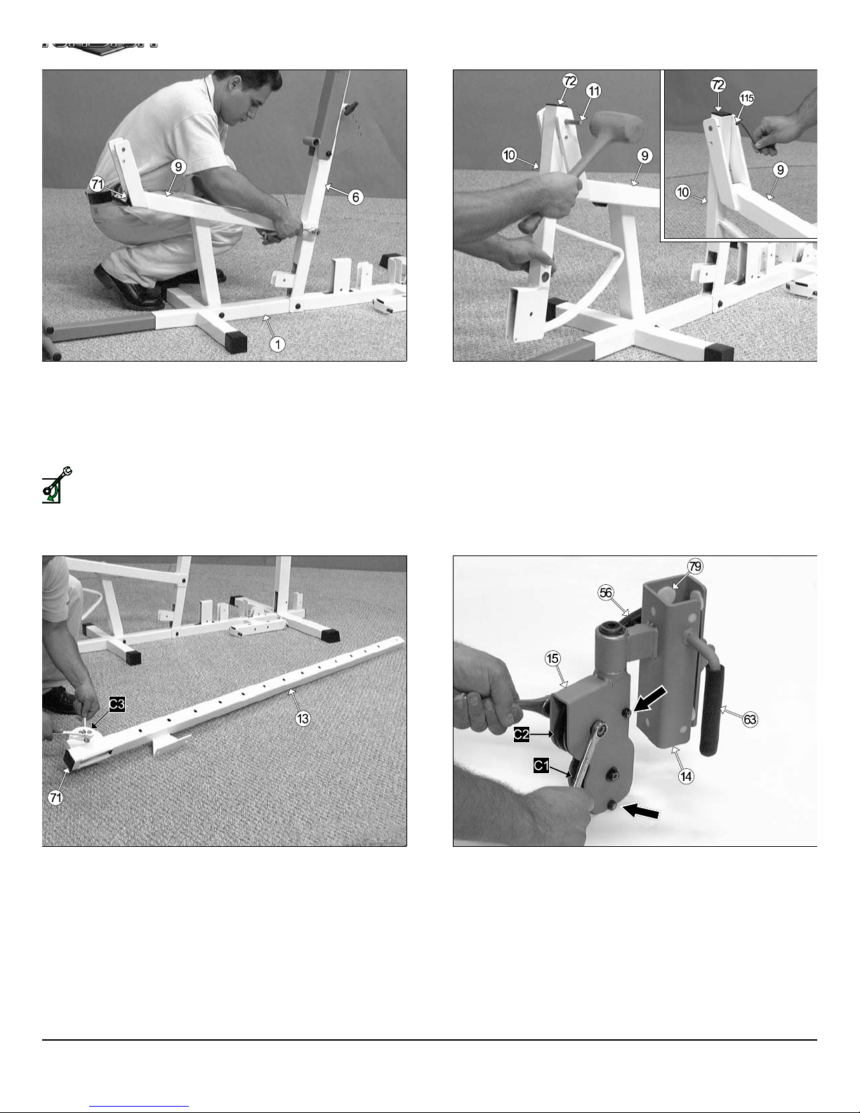
IG. 12 Attach the Leg Extension Bench Frame (#9) to the Base
w
e
s
e
m
rame (#1) and secure it into place using one Hex Head Cap Screw 3/8-
X 4 1/2 (#96), two Flat Washers SAE 3/8” (#87), and one Nylon Insert
m Lock Nut 3/8-16 (#93). Next, attach the Leg Extension Bench
rame (#9) to the Front Upright (#6) and secure it into place using one
ex Head Cap Screw 3/8-16 X 2 3/4 (#100), two Flat Washers SAE
8” (87), and one Nylon Insert Jam Lock Nut 3/8-16 (#93).
Loosely Fasten: Do not completely fasten this hardware
assembly at this time, as it will be completely fastened later in the
assembly process.
SELY FASTEN
ext, using a rubber mallet, insert one Plastic Insert Cap 2” Sq. (#71) into
e front of the Leg Extension Bench Frame (#9).
FIG. 13 Locate the Leg Extension Arm (#10), and using a rubber m
let, insert one Plastic Insert Cap 1 1/2 Sq. (#72) into the tube-end.
above, to the Leg Extension Bench Frame (#9) and secure it into pla
by inserting the Leg Extension Axle 1/2 X 2-3/4 (#11) through the Le
Extension Bench Frame (#9) and Leg Extension Arm (#10) until it b
comes flush with both sides of the Leg Extension Bench Frame (#9).
Leg Extension Bench Frame (#9) using two Set Screws 1/4-20 X 3/
(#52), as shown above. Use the supplied Hex Key 1/8” (#115) f
fastening these Set Screws.
Affix the Leg Extension Arm (#10), in the position as sho
Next, secure the Leg Extension Axle 1/2 X 2-3/4 (#11) to th
IG. 14 Using a rubber mallet, insert a Plastic Insert Cap 2” Sq. (#71)
to the tube-end of the High-Low Selectorized Upright (#13). Next, in-
rt a Nylon Pulley 4-1/2 Rd. (#67-Labeled C#) into the pulley bracket of
e High-Low Selectorized Upright (#13) and secure it into place using
ne Hex Head Cap Screw 3/8-16 x 1 3/4 (#102), two Flat Washers SAE
8” (#87), and one Nylon Insert Jam Lock Nut 3/8-16 (#93)
5
FIG. 15 Insert the two Nylon Pulleys 3 1/2 Rd. (#68) into the High-Lo
Double Pulley Bracket (#15) and secure them into place using two H
Head Cap Screws 3/8-16 x 1 3/4 (#102), four Flat Washers SA
3/8” (#87), and two Nylon Insert Jam Lock Nuts 3/8-16 (#93). Next, a
semble two Hex Head Cap Screws 1/4-20 x 1 1/2 (#104), and two Nylo
Insert Lock Nuts 1/4-20 (#95) to the High-Low Double Pulley Brack
(#15), in the positions indicated by the black arrows.
TS-1000 Home Gym w/Adjustable High-Low Pulley Syste
Page 7
E
6
r
O
wner’s Manual: Assembly Instruction
s
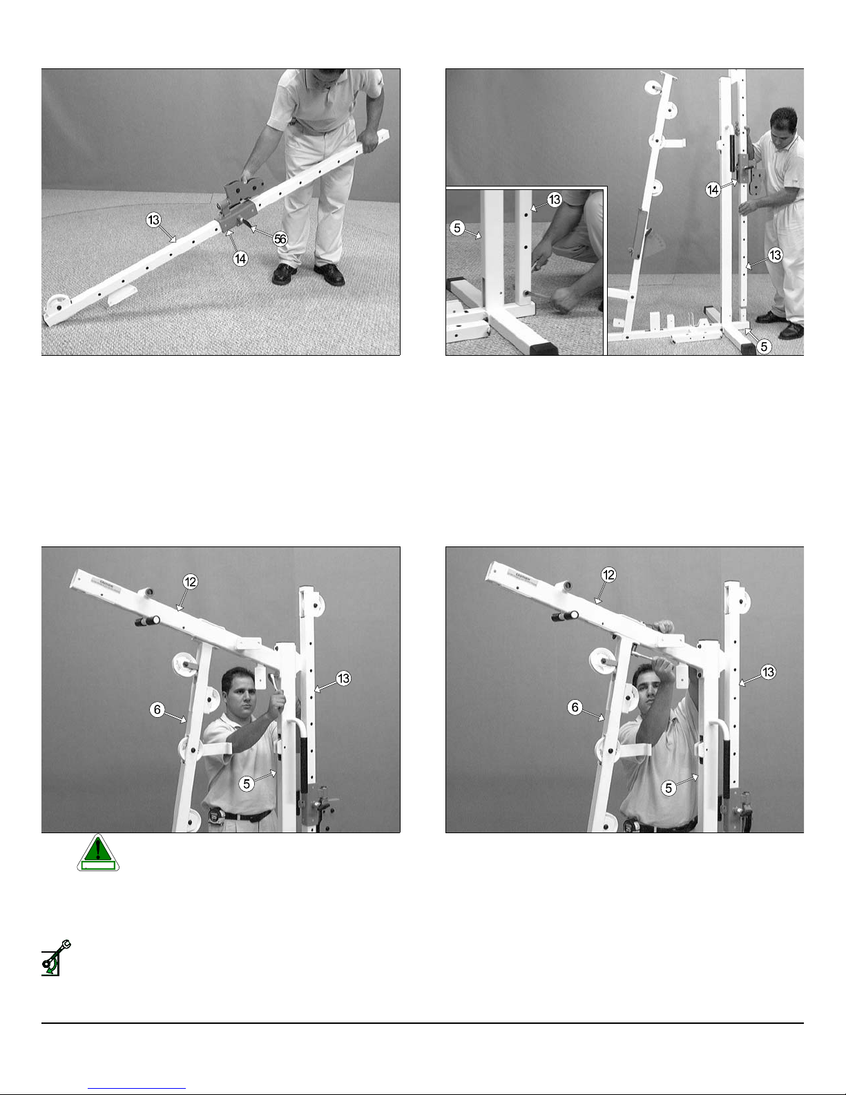
IG. 16 Slide the High-Low Carriage (#14) onto the High-Low Selec-
rized Upright (#13), in the position as shown above. Be sure to release
e Push Pull Pin 1/2 x 3 1/2 (#56) to allow the insertion of carriage as-
mbly.
FIG. 17 Next, insert the High-Low Sectorized Upright (#13) onto th
tube-connector of the Rear Upright (#5) and secure it into place usin
one Hex Head Cap Screw 3/8-16 x 2 1/2 (#101), two Flat Washers SA
3/8” (#87), and one Nylon Insert Jam Lock Nut 3/8-16 (#93).
IG. 18 Caution: It is recommended to use another person in
ount the Top Pulley Assembly (#12) to the Front Upright (6), and affix
to the Rear Upright (#5) and the High-Low Selectorized Upright (#13)
ing two Hex Head Cap Screws 3/8-16 x 4 1/4 (#97), four Flat Washers
AE 3/8” (#87), and two Nylon Insert Lock Nuts 3/8-16 (92).
Loosely Fasten: Do not completely fasten this hardware assembly at this time, as it will be completely fastened later in the assembly process.
SELY FASTEN
assisting with this assembly.
CAUTION
FIG. 19 Affix the Top Pulley Assembly (#12) to the Front Upright (#
using two Hex Head Cap Screws 3/8-16 x 4 1/4 (#97), four Flat Washe
SAE 3/8” (#87), and two Nylon Insert Lock Nuts 3/8-16 (#92).
S-1000 Home Gym w/Adjustable High-Low Pulley System 6
Page 8
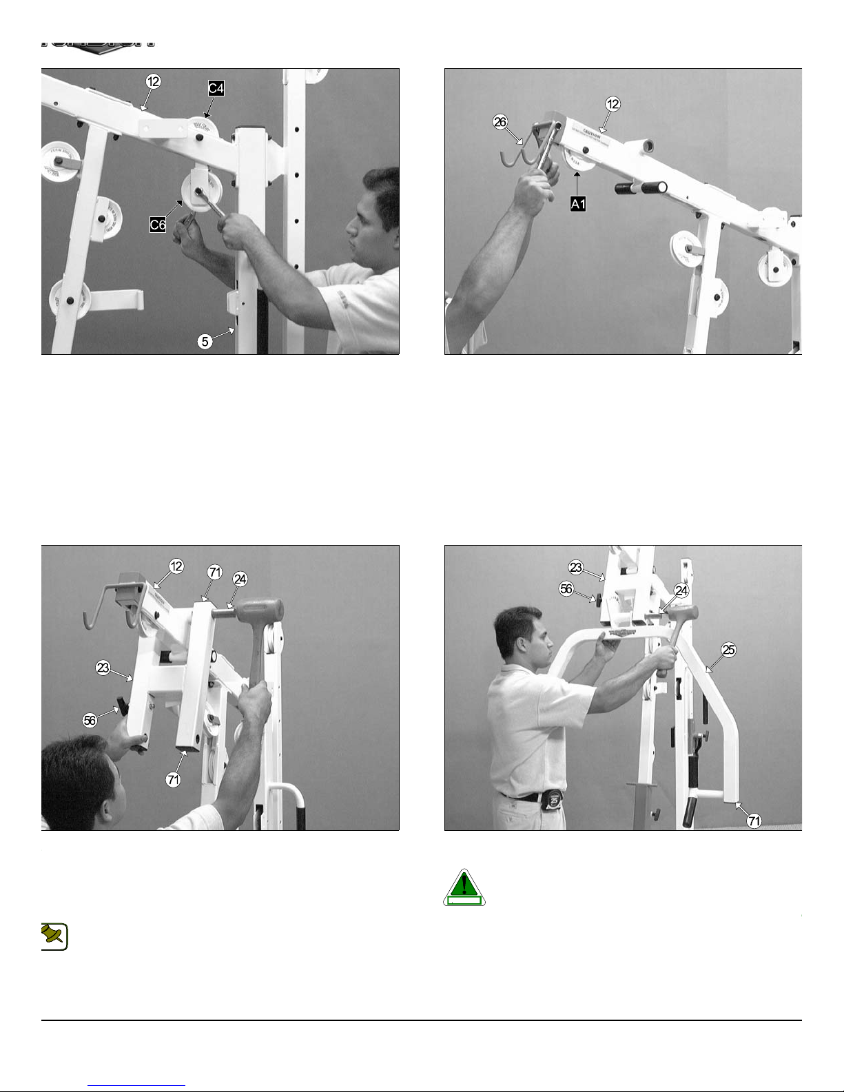
IG. 20 Attach a Nylon Pulley 4 1/2 Rd. (#67-Labeled C4) into the pulley
e
t
a
w
E
o
n
g
a
m
racket located on the Top Pulley Assembly (#12) and secure it into
lace using one Hex Head Cap Screw 3/8-16 x 2 1/2 (#101), two Flat
ashers SAE 3/8” (#67), and one Nylon Insert Jam Lock Nut 3/8-16
93). Next, attach a Nylon Pulley 4 1/2 Rd. (#67-Labeled C6) into the
ulley bracket located on the Top Pulley Assembly (#12) and secure it
to place using one Hex Head Cap Screw 3/8-16 x 1 3/4 (#102), two Flat
ashers SAE 3/8” (#67), and one Nylon Insert Jam Lock Nut 3/8-16
93).
FIG. 21 Attach a Nylon Pulley 4 1/2 Rd. (#67-Labeled A1) into the pull
bracket located on the Top Pulley Assembly (#12) and secure it in
place using one Hex Head Cap Screw 3/8-16 x 2 1/2 (#101), two Fl
Washers SAE 3/8” (#67), and one Nylon Insert Jam Lock Nut 3/8-1
(#93). Next, attach the Lat Bar Holder (#26), in the position as sho
above, to the Top Pulley Assembly (#12) and secure it into place usin
one Hex Head Cap Screw 3/8-16 x 2 3/4 (#100), two Flat Washers SA
3/8” (#67), and one Nylon Insert Jam Lock Nut 3/8-16 (#93).
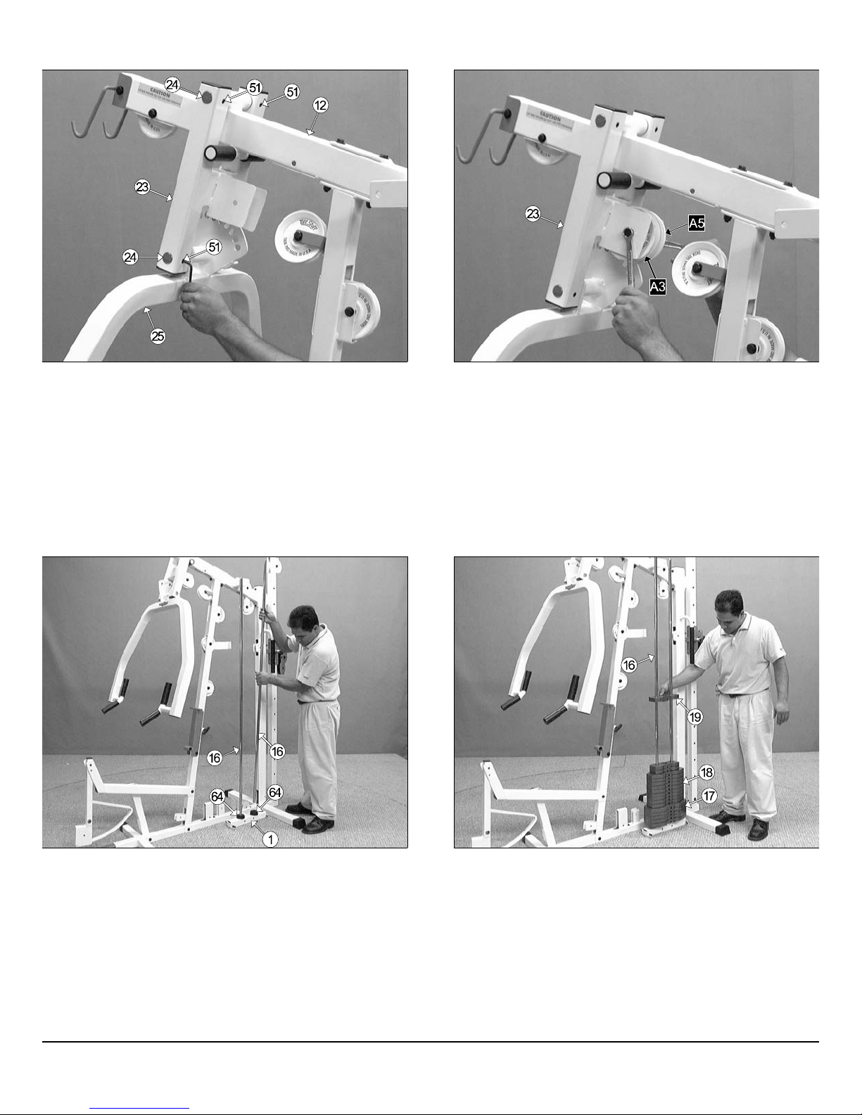
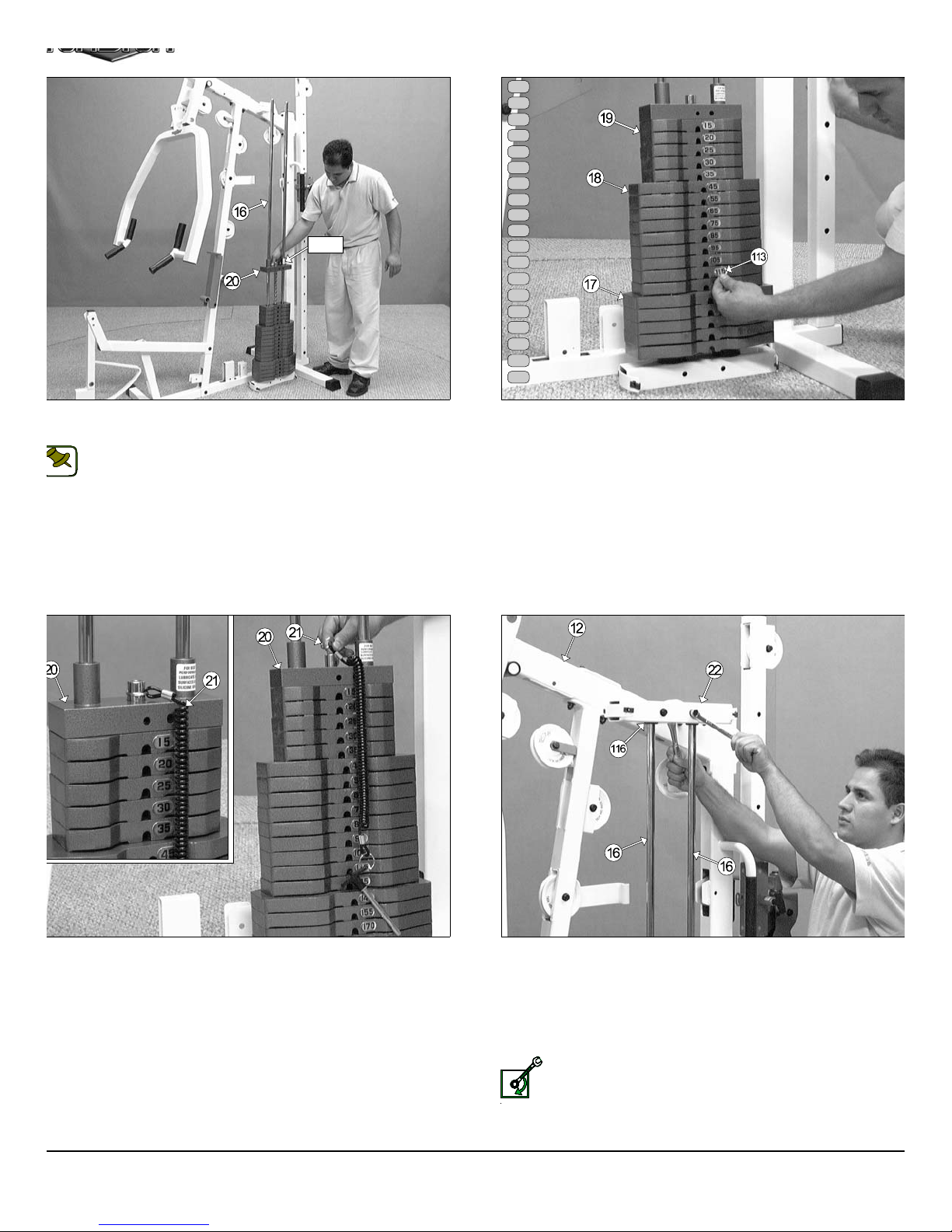
IG. 22 Attach the Press Bar Selector Housing (#23) to the Top
ulley Assembly (#512), as shown above. Using a rubber mallet, insert
Pivot Axle 1 X 8 1/8 (#24) through the holes in the Press Bar Selector
ousing (#23) and through the receptacle on the Top Pulley Housing
12) until it is flush with both sides of the Press Bar Selector Housing
23).
Note:The four Plastic Insert Caps 2” Sq. (#71) located in the tubeends of the Press Bar Selector Housing (#23) have been pre-
OTE:
assembled by the factory.
7
FIG. 23 Insert two Plastic Insert Caps 2” Sq. (#71) into the tube-end
the Press Bar (#25).
Caution: It is recommended to use another person in assisti
with this assembly.
CAUTION
Next, insert the Press Bar (#25) up into the Press Bar Selector Housin
(#23) and support in into place using the Push Pull Pin (#56). Next, usin
a rubber mallet, insert the Pivot Axle 1 X 8 1/8 (#24) into the Press B
Selector Housing (#23) and through the Press Bar (#25) until it is flus
with both sides of the Press Bar Selector Housing (#23).
TS-1000 Home Gym w/Adjustable High-Low Pulley Syste
Page 9
5
5
m
o
b
O
wner’s Manual: Assembly Instruction
s
IG. 24 Next, secure the Press Bar Selector Housing (#23) to the
ivot Axle 1 X 8 1/8 (#24) using two Set Screws 3/8-16 X 1/2 (#51), as
own above. Then, secure into place the Press Bar (#25) to the Pivot
xle 1 X 8 1/8 (#24) using two Set Screws 3/8-16 X 1/2 (#51). Use the
upplied Hex Key 3/16 (#114) for securing the Set Screws 3/8-16 X 1/2
51) into the threaded sockets on the Press Bar Selector Housing
23).
FIG. 25 Next, attach two Nylon Pulleys 4 1/2 Rd. (#67-Labeled A3, A
to the pulley bracket located on the Press Bar Selector Housing (#2
and secure them into place using one Hex Head Cap Screw 3/8-16 X
3/4 (#100), two Flat Washers SAE 3/8” (#87), and one Nylon Insert Ja
Lock Nut 3/8-16 (#93).
IG. 26 Insert one Rubber Donut 3/4 x 2 1/2 (#64) onto each Guide
od 3/4 x 72 (#16). Next, insert the two Guide Rods 3/4 x 72 (#16) into
e receptacles on the Base Frame (#1), as shown above.
FIG. 27 Carefully begin sliding the Weight Plates over the Guid
Rods (#16) beginning with the five 15 Lb. Weight Plates (#17) at the b
tom, the nine 10 Lb. Weight Plates (#18) in the middle, and the five 5 L
Weight Plates (#19) on top of the weight stack.
S-1000 Home Gym w/Adjustable High-Low Pulley System 8
Page 10
e
p
e
x
v
t
r
h
m
Label
LOOSELY FASTEN
15
20
25
30
35
45
55
65
75
85
95
105
115
125
140
155
170
185
200
IG. 28 Slide the Top Plate/Selector Bar (#20) over the Guide Rods
16) allowing it to come to rest on the completed weight stack.
Note: Be sure the Label located on the Top Plate/Selector Bar
(#20) is facing toward you before you slide the Top Plate/Selector
NOTE:
Bar (#20) over the Guide Rods 3/4 X 72 (#16).
FIG. 29 Attach the Decal Weight Numbers (#113) to the Weight Plat
(#17, #18, #19) in the corresponding order. Begin with the 15 at the to
20 next, and so on.
IG. 30 Next, locate the Selector Pin w/Coil (#21) and slide its ring
er the Selector Bar (#20) as shown above.
9
FIG. 31 Maneuver the two Guide Rods 3/4 X 72 (#16) into the hol
on the bottom side of the Guide Rod Retainer Housing (#22).Ne
mount the Guide Rod Retainer Housing (#22) along with the two capti
Guide Rods 3/4 X 72 (#16) to the side of the Top Pulley Assembl
(#12). Secure this assembly using two Hex Head Cap Screws 3/8-16 X
(#112), four Flat Washers SAE 3/8” (#87), and two Nylon Insert Lock Nu
3/8-16 (#92).
Loosely Fasten: Do not completely fasten this hardwa
assembly at this time, as it will be completely fastened later in t
assembly process.
TS-1000 Home Gym w/Adjustable High-Low Pulley Syste
Page 11
e
c
s
O
wner’s Manual: Assembly Instruction
s
n
c
a
l
a
)
m
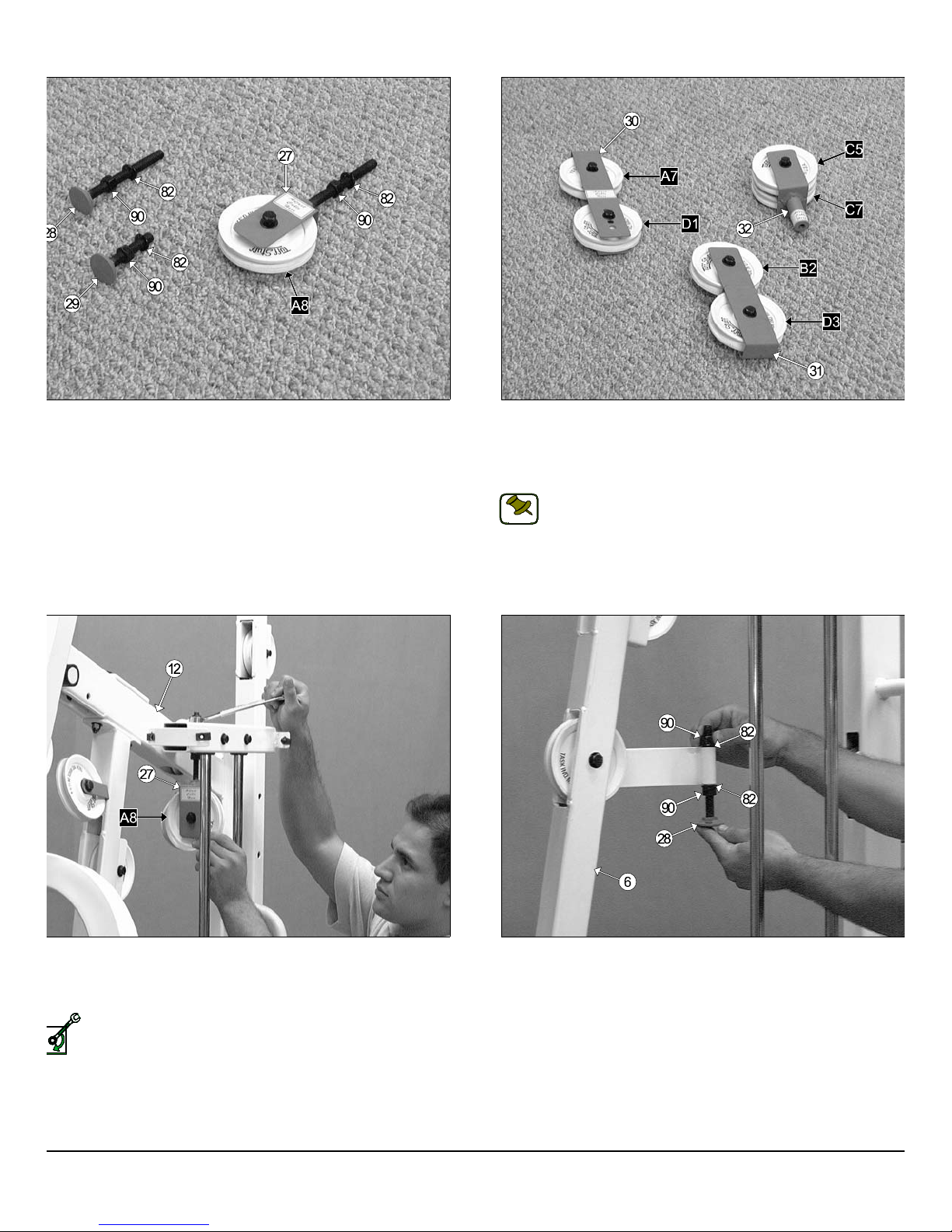
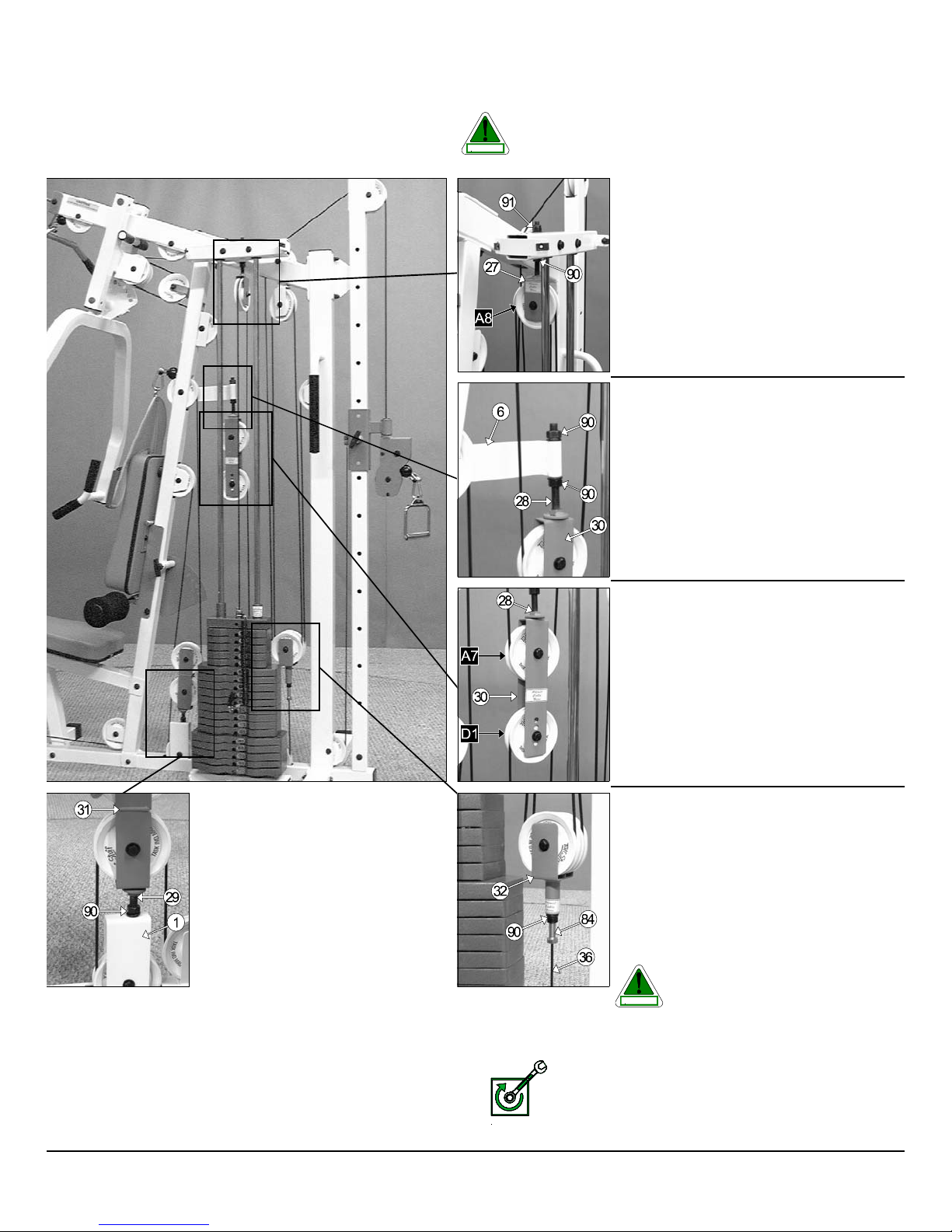
IG. 32 First, locate the Adjustable Pulley Bracket (#27) and insert
ne Nylon Pulley 4 1/2 Rd. (#67-Labeled A8). Secure the Nylon Pulley 4
2 Rd. (#67-Labeled A8) into place using one Hex Head Cap Screws 3/8-
X 1 3/4 (#102), two Flat Washers SAE 3/8” (#87), and one Nylon Insert
m Lock Nut 3/8-16 (#93). Next, thread one Regular Hex Nut 1/2-13
90), and insert one Split Washer B/O 1/2” (#82) over the bolt on the
djustable Pulley Bracket (#27), as shown above. Second, locate the
o Adjustable Stoppers (#28, #29) and thread one Regular Hex Nut
2-13 (#90), and insert one Split Washer B/O 1/2” (#82) over each bolt,
shown above.
FIG. 33 Locate the Closed-End Adj. Double Pulley Bracket (#30), a
the Closed-End Double Pulley Bracket (#31). Then, attach four Nylo
Pulleys 4 1/2 Rd. (#67-Labeled D3,B2,D1,A7). Secure them into pla
using four Hex Head Cap Screws 3/8-16 X 1 3/4 (#102), eight Fl
Washers SAE 3/8” (#87), and four Nylon Insert Jam Lock Nuts 3/8-1
(#93).
Note: The four holes on the Closed-End Adj. Double Pulle
Bracket (#30) are used to adjust the cable tension once the cab
NOTE:
routing has been completed.
Next, locate the Floating Double Pulley Bracket (#32), shown above
the right, and attach two Nylon Pulleys 4 1/2 Rd. (#67-Labeled C7,C5
Secure the pulleys into place using one Hex Head Cap Screw 3/8-16 X
3/4 (#100), two Flat Washers SAE 3/8” (#87) and one Nylon Insert Ja
Lock Nut 3/8-16 (#93).
IG. 34 Insert the welded bolt of the Adjustable Pulley Bracket (#27)
rough the hole located on the Top Pulley Assembly (#12) and secure it
to place at the top using one Flat Washer SAE 1/2” (#86), and one Nylon
sert Lock Nut 1/2-13 (#91).
Loosely Fasten: Do not completely fasten this hardware assembly at this time, as it will be completely fastened later in the assembly process.
SELY FASTEN
FIG. 35 Insert (from bottom to top) the Long Adjustable Stopp
(#28) into the receptacle of the Front Upright (#6) and secure it into pla
using one Split Washer B.O. 1/2” (#82), and one Regular Hex Nut 1/2-1
(#90), as shown above. Loosely fasten the Regular Hex Nuts 1/2-1
(#84) to allow adjustment for cables tension later in the assembly proces
S-1000 Home Gym w/Adjustable High-Low Pulley System 10
Page 12

IG. 36 Thread the Short Adjustable Stopper (#29) into the threaded
o
n
e
d
e
m
cket on the Base Frame (#1), as shown above.
Loosely Fasten: Do not completely fasten this hardware assembly at this time, as it will be completely fastened later in the assembly process.
SELY FASTEN
FIG. 37 Begin routing the Lat Cable (#33) up and over the Nyl
Pulley 4 1/2 Rd. (#67-Labeled A1) and into the tube of the Top Pulle
Assembly (#12). Then, pull the Lat Cable (#33) down through the ope
ing at the bottom of the Top Pulley Assembly (#12).
Note: Refer to the Cable Mapping Diagram on page 24 for furth
detailed illustration of the Lat Cable (#33) routing.
NOTE:
IG. 38 Insert a Nylon Pulley 4 1/2 Rd. (#67-Labeled A1) into the slot
the bottom of the Top Pulley assembly (#12) and secure it into place
ing one Hex Head Cap Screw 3/8-16 X 2 1/2 (#101), two Flat Washers
AE 3/8” (#87), and one Nylon Insert Jam Lock Nut 3/8-16 (#93). Be sure
e cable is routed properly into the groove on the Nylon Pulley 4 1/2 Rd.
67-Labeled A1).
Note: Refer to the Cable Mapping Diagram on page 24 for further
detailed illustration of the Lat Cable (#33) routing.
NOTE:
11
FIG. 39 Next, route the Lat Cable (#33) over the Nylon Pulley 4-1/2 R
(#67-Labeled A3).
Note: Refer to the Cable Mapping Diagram on page 24 for furth
detailed illustration of the Lat Cable (#33) routing.
NOTE:
TS-1000 Home Gym w/Adjustable High-Low Pulley Syste
Page 13

e
a
e
6
e
O
wner’s Manual: Assembly Instruction
s
IG. 40 Next, route the Lat Cable (#33) up and over the Nylon Pulley
1/2 Rd. (#67-Labeled A4).
Note: Refer to the Cable Mapping Diagram on page 24 for further
detailed illustration of the Lat Cable (#33) routing.
NOTE:
FIG. 41 Next, continue to route the Lat Cable (#33) over the Nylo
Pulley 4 1/2 Rd. (#67-Labeled A5), then through the Front Upright (#
and over the Nylon Pulley 4 1/2 Rd. (#67-Labeled A6).
Note: Refer to the Cable Mapping Diagram on page 24 for furth
detailed illustration of the Lat Cable (#33) routing.
NOTE:
IG. 42 Next, route the Lat Cable (#33) through the Closed-End Adj.
ouble Pulley Bracket (#30) and under the Nylon Pulley 4 1/2 Rd. (#67-
beled A7), as shown above.
Note: Refer to the Cable Mapping Diagram on page 24 for further
detailed illustration of the Lat Cable (#33) routing.
NOTE:
FIG. 43 Next, route the Lat Cable (#33) through the Adjustable Pull
Bracket (#27) and over the Nylon Pulley 4 1/2 Rd. (#67-Labeled A8),
shown above.
Note: Refer to the Cable Mapping Diagram on page 24 for furth
detailed illustration of the Lat Cable (#33) routing.
NOTE:
S-1000 Home Gym w/Adjustable High-Low Pulley System 12
Page 14

4
e
4
IG. 44 Next, attach the Lat Cable (#33) to the Top Plate/ Selector
a
t
i
l
m
ar (#20) and secure it into place using one Split Bolt 1/2-13 x 1 (#85),
nd one Split Washer Z/P 1/2” (#83). Refer to Fig. B on page 24 for
rther illustration of this hardware assembly.
Fully Fasten: Proceed to fully fasten this hardware assembly.
LY FASTEN
FIG. 45 Before beginning routing the Leg Extension/Abdomin
Cable (#34) it is necessary to remove the Adjustabl
CAUTION
the Leg Extension Bench Frame (#9) to the Front Up Right (#6). Th
is done to ensure the Leg Extension/Abdominal Cable (#34) be proper
routed. Otherwise the Cable will get tangled between the bolts that hol
these assemblies.
Back Pad Bracket (#7) and the Hardware that connec
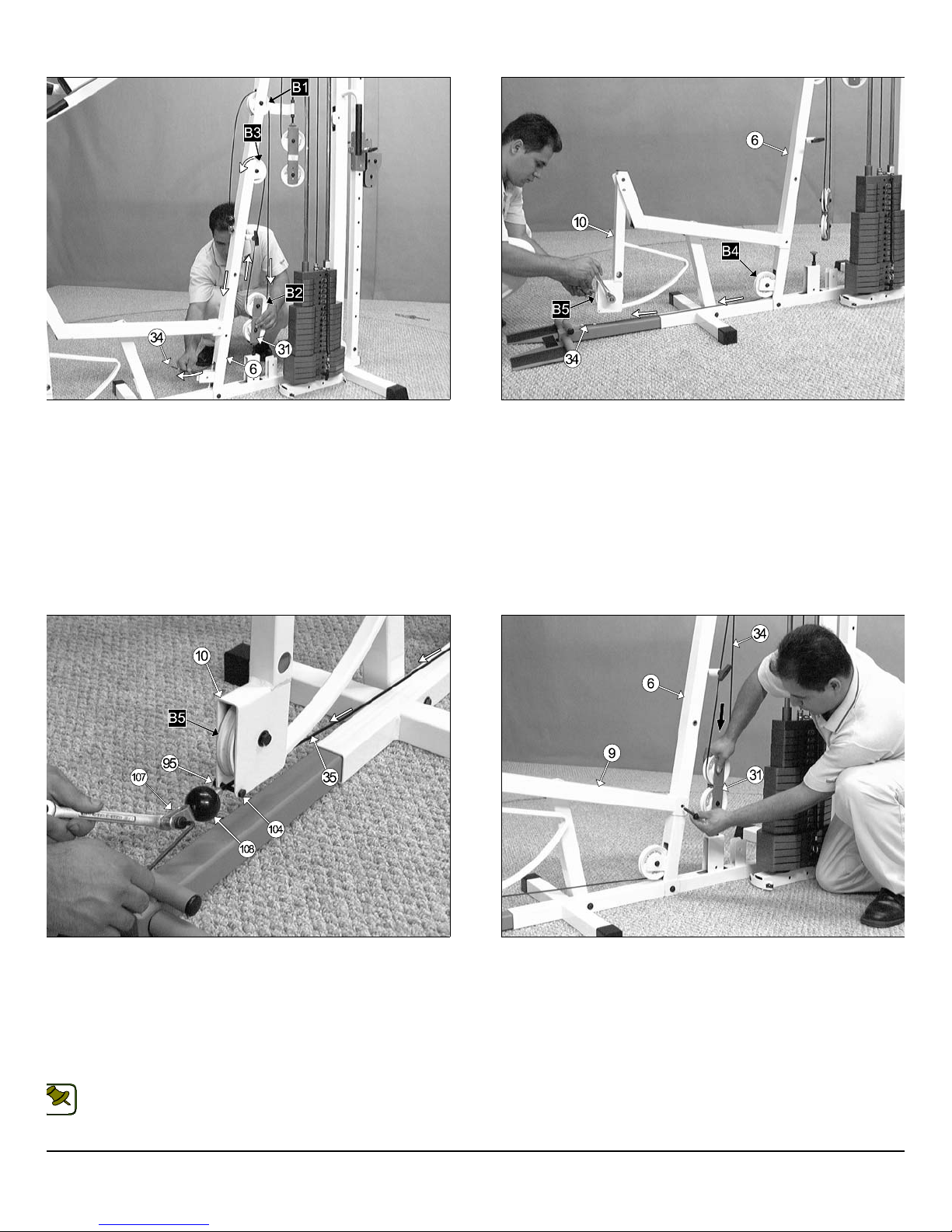
IG. 46 Remove the hardware from one end of the Leg Extension/
bdominal Cable (#34). Next, begin routing the Leg Extension/
bdominal Cable (#34) through the opening of the Front Upright (#6)
nd over the Nylon Pulley 4 1/2 Rd. (#67-Labeled B1).
Note: Refer to the Cable Mapping Diagram on page 25 for further
detailed illustration of the Leg Extension/Abdominal Cable (#34)
NOTE:
routing.
13
FIG. 47 Next, route the Leg Extension/Abdominal Cable (#3
through the Closed-end Double Pulley Bracket (#31) and under th
Nylon Pulley 4 1/2 Rd. (#67-Labeled B2), as shown above.
Note: Refer to the Cable Mapping Diagram on page 25 for furth
detailed illustration of the Leg Extension/Abdominal Cable (#3
NOTE:
routing.
TS-1000 Home Gym w/Adjustable High-Low Pulley Syste
Page 15
e
6
e
E
O
wner’s Manual: Assembly Instruction
s
IG. 48 Continue to route the Leg Extension/Abdominal Cable (#34)
p and over the Nylon Pulley 4 1/2 Rd. (#67-Labeled B3), then down into
e Front Upright’s (#6) tube. Next, pull the Leg Extension/Abdominal
able (#34) through the opening at the bottom of the Front Upright (#6).
ote: Refer to the Cable Mapping Diagram on page 25 for further detailed
ustration of the Leg Extension/Abdominal Cable (#34)routing.
FIG. 49 Insert two Nylon Pulleys 4 1/2 Rd. (#67-Labeled B4), one to th
bottom pulley bracket of the Front Upright (#6) and the other to the pull
bracket of the Leg Extension Arm (#10). Secure them into place usin
two Hex Head Cap Screws 3/8-16 x 1 3/4 (#102), four Flat Washers SA
3/8” (#87), and two Nylon Insert Jam Lock Nuts 3/8-16 (#93).
IG. 50 Route the Leg Extension/Abdominal Cable (#34) up to the
eg Extension Arm (#10). Then, affix a Nylon Ball 1 3/4 x 5/16 (#108),
nd a Strap Bracket #20 (#107) to the cable end. Lock them into place
ing a Shoulder Bolt 3/8 x 3/4 (#106), and a Nylon Insert Lock Nut 5/16 (#94).
eg Extension Arm (#10) using one Hex Head Cap Screw 1/4-20 (#104),
nd one Nylon Insert Lock Nut 1/4-20 (#95). Refer to Fig. C on page 25
NOTE:
Next, secure the Leg Extension/Abdominal Cable (#34) to the
r further illustration of this hardware assembly.
Note: Refer to the Cable Mapping Diagram on page 25 for further
detailed illustration of the Leg Extension/Abdominal Cable (#34)
routing.
FIG. 51 Press down the Closed-End Double Pulley Bracket (#31) t
apply tension to the Leg Extension/Abdominal Cable (#34). Then, r
attach the Leg Extension Bench Frame (#9) to the Front Upright (#
using the previously removed Hardware (one Hex Head Cap Screw 3/8-1
x 2 3/4 (#100), two Flat Washers SAE 3/8” (#87), and one Nylon Inse
Jam Lock Nut 3/8-16 (#93).
S-1000 Home Gym w/Adjustable High-Low Pulley System 14
Page 16
4
y
e
IG. 52 Press down the Closed-End Double Pulley Bracket (#31) to
/
w
e
m
pply tension to the Leg Extension/Abdominal Cable (#34). Then, re-
tach the Adjustable Back Pad Bracket (#7) to the Front Upright (#6)
ing the previously removed Hardware (one Hex Head Cap Screw 3/8-16
3 1/4 (#99), two Flat Washers SAE 3/8” (#87), two Nylon Flat Washer
8” (#88), and one Nylon Insert Jam Lock Nut 3/8-16 (#93).
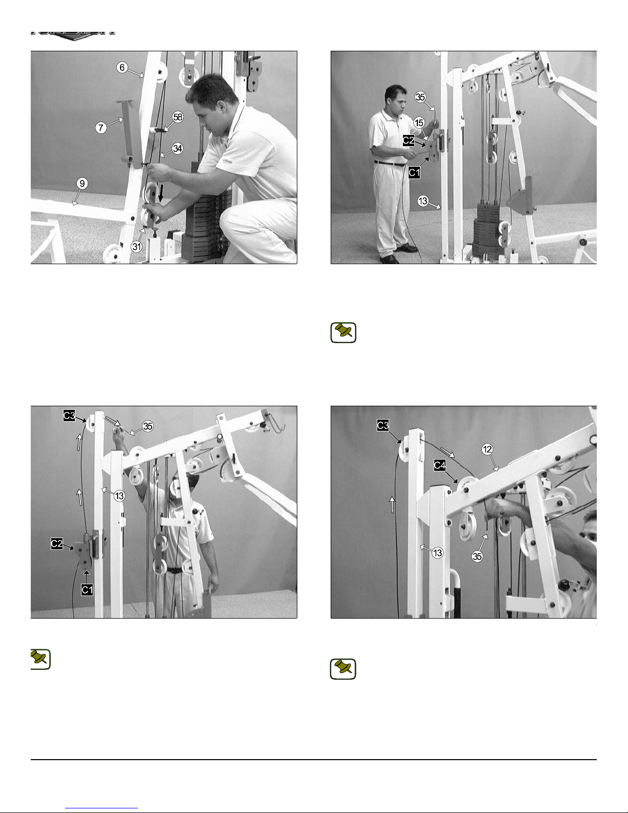
FIG. 53 Route the High-Low Cable (#35) between the two Nylon Pu
leys 3 1/2 Rd. (#68-Labeled C1, C2), then up between the Nylon Pulley
1/2 Rd. (#68-Labeled C2) and the Hex Head Cap Screw 1/4-20 x 1 1
(#104). Continue routing the cable up through the tube of the High-Lo
Double Pulley Bracket (#15).
Note: Refer to the Cable Mapping Diagram on page 26 for furth
detailed illustration of the High-Low Cable (#35) routing.
NOTE:
IG. 54 Route the High-Low Cable (#35) up and over the Nylon Pulley
1/2 Rd. (#67-Labeled C3)
Note: Refer to the Cable Mapping Diagram on page 26 for further
detailed illustration of the High-Low Cable (#35) routing.
NOTE:
15
FIG. 55 Route the High-Low Cable (#35) down to the Nylon Pulley
1/2 Rd. (#67-Labeled C4) passing through the opening of the Top Pulle
Assembly (#12).
Note: Refer to the Cable Mapping Diagram on page 26 for furth
detailed illustration of the High-Low Cable (#35) routing.
NOTE:
TS-1000 Home Gym w/Adjustable High-Low Pulley Syste
Page 17
b
a
E
d
e
y
e
O
wner’s Manual: Assembly Instruction
s
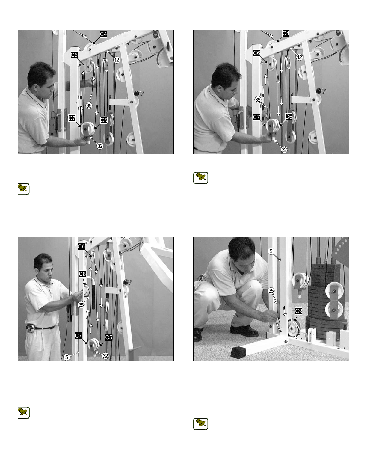
IG. 56 Next, locate the Floating Double Pulley Bracket (#32) and
ntinue to route the High-Low Cable (#35) down and under the Nylon
ulley 4 1/2 Rd. (#67-Labeled C5). Then, up and over the Nylon Pulley 4
2” Rd. (#67-Labeled C6).
Note: Refer to the Cable Mapping Diagram on page 26 for further
detailed illustration of the High-Low Cable (#35) routing.
OTE:
FIG. 57 Next, route the High-Low Cable (#35) down and under the N
lon Pulley 4 1/2 Rd. (#67-Labeled C7).
Note: Refer to the Cable Mapping Diagram on page 26 for furth
detailed illustration of the High-Low Cable (#35) routing.
NOTE:
IG. 58 Next, route the High-Low Cable (#35) down into the tube of
e Rear Upright (#5). Next, insert a Nylon Pulley 4 1/2 Rd. (#67-Labeled
8) into the slot of the Rear Upright (#5) and secure it into place using
ne Hex Head Cap Screw 3/8-16 X 2 1/2 (#101), two Flat Washers SAE
8” (#87), and one Nylon Insert Jam Lock Nut 3/8-16 (#93). Be sure the
ble is routed properly into the groove on the Nylon Pulley 4 1/2 Rd.
67-Labeled C8).
FIG. 59 Continue routing the High-Low Cable (#35) down into the tu
of the Rear Upright (#5). Next, pull the Cable end through the opening
the bottom of the Rear Upright (#5). Then, route the cable around
Nylon Pulley 4 1/2 Rd. (#67-Labeled C9), as shown above. Secure th
Nylon Pulley 4 1/2 Rd. (#67-Labeled C9) to the Rear Upright (#5) usin
one Hex Head Cap Screw 3/8-16 X 2 1/2 (#101), two Flat Washers SA
3/8” (#87), and one Nylon Insert Jam Lock Nut 3/8-16 (#93). Be sure th
cable is routed properly into the groove on the Nylon Pulley 4 1/2 R
Note: Refer to the Cable Mapping Diagram on page 26 for further
detailed illustration of the High-Low Cable (#35) routing.
NOTE:
(#67-Labeled C9).
Note: Refer to the Cable Mapping Diagram on page 26 for furth
detailed illustration of the High-Low Cable (#35) routing.
NOTE:
S-1000 Home Gym w/Adjustable High-Low Pulley System 16
Page 18
o
e
IG. 60 Next, route the High-Low Cable (#35) up to the High-Low Car-
e
w
c
s
m
age (#14) and insert the cable to the welded bracket on the side of the
igh-Low Carriage (#14), as shown in caption above. Lock the High-
ow Cable (#35) into place using one Shoulder Bolt 3/8 x 3/4 (#106), and
ne Nylon Insert Lock Nut 5/16-18 (#94).
Note: Refer to the Cable Mapping Diagram on page 26 for further
detailed illustration of the High-Low Cable (#35) routing.
OTE:
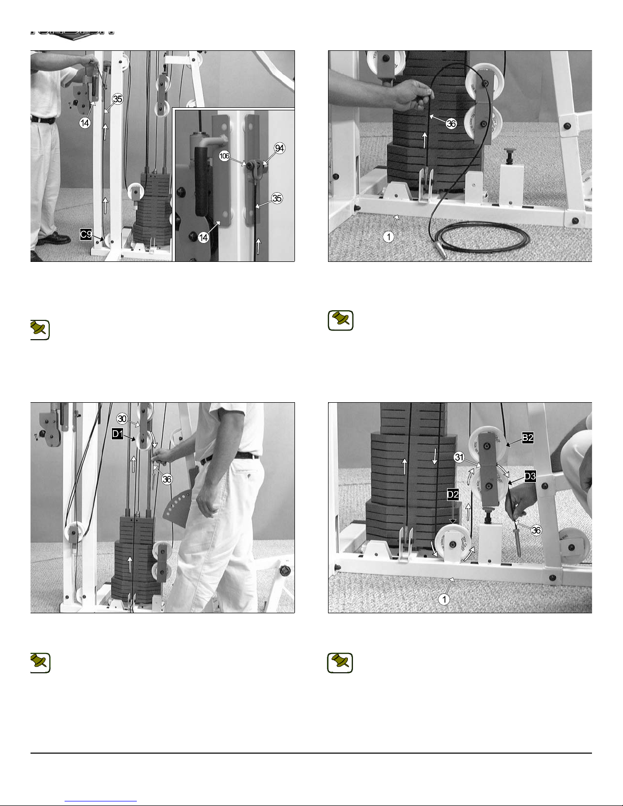
FIG. 61 Affix the looped end of the Tension Cable (#36) to the pull
bracket located on the Base Frame (#1) using one Hex Head Cap Scre
3/8-16 x 1 3/4 (#102), two Flat Washers SAE 3/8” (#87), two Nylon spa
ers 3/8 x 3/8 (#109), and one Nylon Insert Jam Lock Nut 3/8-16 (#93).
Note: Refer to Fig F on page 27 for further illustration of this a
sembly.
NOTE:
IG. 62 Route the Tension Cable (#36) up to the Closed-End Adj.
ouble Pulley Bracket (#30) and over the Nylon Pulley 4 1/2 Rd (#67-
beled D1), as shown above.
Note: Refer to the Cable Mapping Diagram on page 27 for further
detailed illustration of the Tension Cable (#36) routing.
NOTE:
17
FIG. 63 Continue routing the Tension Cable (#36) down and under th
Nylon Pulley 4 1/2 Rd (#67-Labeled D2). Then, up and over the Nyl
Pulley 4 1/2 Rd (#67-Labeled D3).
Note: Refer to the Cable Mapping Diagram on page 27 for furth
detailed illustration of the Tension Cable (#36) routing.
NOTE:
TS-1000 Home Gym w/Adjustable High-Low Pulley Syste
Page 19
d
O
a
u
m
s
e
O
wner’s Manual: Assembly Instruction
s
LOOSELY FASTEN
IG. 64 Route the Tension Cable (#36) into the tube of Base Frame
1) then pull it out through the opening at the top of the Base Frame
1). Next, insert two Nylon Pulleys 4 1/2 Rd (#67-Labeled D4, D5) to the
ulley brackets located on the Base Frame (#1) and secure them into
lace using two Hex Head Cap Screws 3/8-16 x 1 3/4 (#102), four Flat
ashers SAE 3/8” (#87), and two Nylon Insert Jam Lock Nuts 3/8-16
93). Be sure the cable is routed properly into the grooves of the Nylon
ulleys 4 1/2 Rd. (#67-Labeled D4, D5), as shown above.
Note: Refer to the Cable Mapping Diagram on page 27 for further
detailed illustration of the Tension Cable (#36) routing.
NOTE:
FIG. 65 Conclude the routing of the Tension Cable (#36) by Threa
ing a Regular Hex Nut 1/2-13 (#90) and inserting a Split Washer B/
1/2” (#82) to the Hex Tap Bolt 1/2-13 x 3 (#84). Then, thread the Hex T
Bolt 1/2-13 x 3 (#84) to the threaded socket located on the Floating Do
ble Pulley Bracket (#32).
Loosely Fasten: Do not completely fasten this hardware asse
bly at this time, as it will be completely fastened later in the a
sembly process.
Note: Refer to the Cable Mapping Diagram on page 27 for furth
detailed illustration of the Tension Cable (#36) routing.
NOTE:
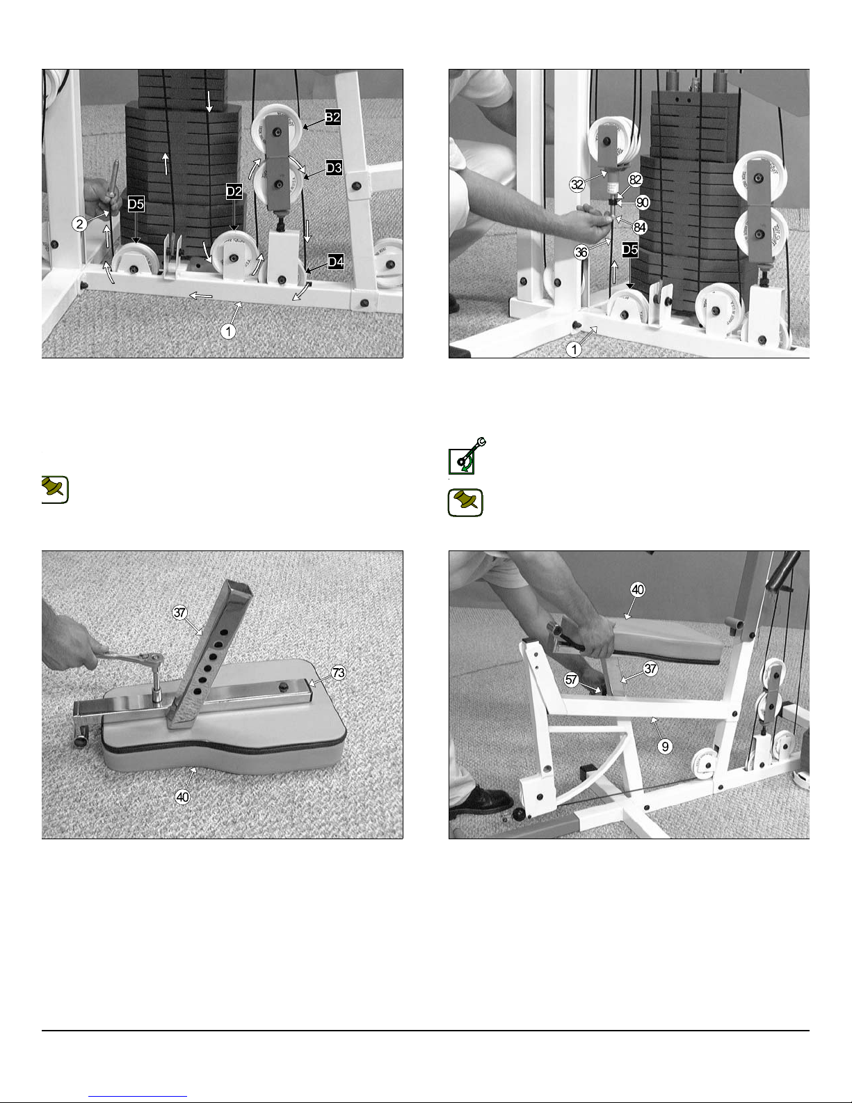
IG. 66 Next, using a rubber mallet, insert a Plastic Insert Cap 1 X 2
73) into the tube-end of the Adjustable Seat Frame (#37). Next, locate
e Seat Pad (#40) and attach it to the Adjustable Seat Frame (#37), as
own above, using two Hex Head Cap Screws 3/8-16 X 1 3/4 (#102),
nd two Flat Washers SAE 3/8” (#87).
FIG. 66 Insert the assembled Adjustable Seat Frame (#37) into th
Leg Extension Bench Frame (#9), in the position as shown above. B
sure to release the Turn/Pull Pin w/Knob (#557) as you begin inserting th
assembled Adjustable Seat Frame (#37) into the Leg Extension Benc
Frame (#9).
S-1000 Home Gym w/Adjustable High-Low Pulley System 18
Page 20
m
IG. 68 Next, insert a Foot Roll Tube 1 X 16 (#4) into the receptacle
4
n
b
a
m
the Adjustable Seat Frame (#37). Then, insert another Foot Roll
ube 1 X 16 (#34) into the receptacle of the Leg Extension Arm (#10).
ext, insert the Foot Roll Tube 1 X 27 (#38) into the receptacle of the
djustable Back Pad Bracket (#7), as shown above.
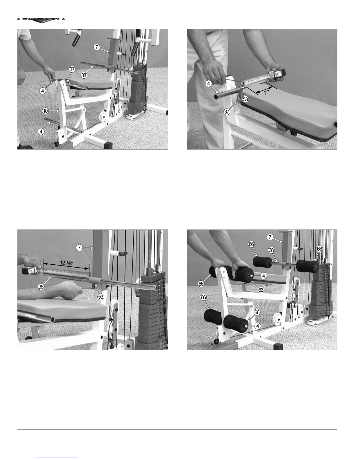
FIG. 69 Use a measuring tape to center the Foot Roll tube 1 x 16 (#
with the Adjustable Seat Frame’s (#37) receptacle. The measureme
from one end of the tube to the receptacle, as picture above, should
about 7”. Secure the Foot Roll Tube 1 X 16 (#4) to the Adjustable Se
Frame (#37) using a Set Screw 1/4-20 X 1/4 (#53), as shown above. Us
the supplied Hex Key 1/8” (#115) to properly secure the Set Screw 1/4-2
X 1/4 (#53) into place.
IG. 70 Use a measuring tape to center the Foot Roll Tube 1 x 27
38) with the Adjustable Back Pad Bracket’s (#7) receptacle. The
easurement from one end of the tube to the receptacle, as pictured
bove, should be about 12 1/8”. Secure the Foot Roll Tube 1 X 27 (#38)
the Adjustable Back Pad Bracket (#7) using a Set Screw 1/4-20 X 1/4
53), as shown above. Use the supplied Hex Key 1/8” (#115) to properly
cure the Set Screw 1/4-20 X 1/4 (#53) into place.
19
FIG. 71 Next, attach one Foam Foot Roll 7 X 4 X 1 (#62) to each en
of the three tubes as shown above. Refer to the Exploded View Diagra
on fold out page for further clarification of this assembly.
TS-1000 Home Gym w/Adjustable High-Low Pulley Syste
Page 21
a
a
o
s
n
o
O
wner’s Manual: Assembly Instruction
s
IG. 59 Attach two Metal Hinges (#50) to the axle of the Adjustable
ack Pad Bracket (#7). Be sure to position the Metal Hinges (#50) as
own above.
FIG. 60 Next, attach the Back Pad (#39) to the Metal Hinges (#50),
shown above, and secure them into place (at the top hole of the Met
Hinge) using two Hex Head Cap Screws 3/8-16 X 1 1/4 (#103), and tw
Flat Washers SAE 3/8” (#87).
IG. 61 Insert a Rubber Grip 1 x 6 1/4 (#62) over each one of the tubends of the Low Row Bar 20” (#42), and the Lat Bar 48” (#41), as shown
bove.
Note: To facilitate the insertion of these Rubber Grips, use Windex
or household glass cleaner.
NOTE:
S-1000 Home Gym w/Adjustable High-Low Pulley System
FIG. 62 Next, attach a Snap Link (#110) to the Lat Cable (#33), in th
position as shown above, and secure it into place using one Shoulder B
3/8 x 3/4 (#106), and one Nylon Insert Lock Nut 5/16-18 (#94). Use th
supplied Hex Key 3/16” (#114) and a 1/2” combination wrench to faste
this assembly properly.
Note: Refer to Fig. A on page 24 for further illustration of this a
sembly.
NOTE:
Connect the Lat Bar 48” (#41) to the Lat Cable (#33) using the Snap Li
(#110). Use the Lat Bar Holder (#26) to rest the Lat Bar 48” (#41) ont
when not in use
20
Page 22
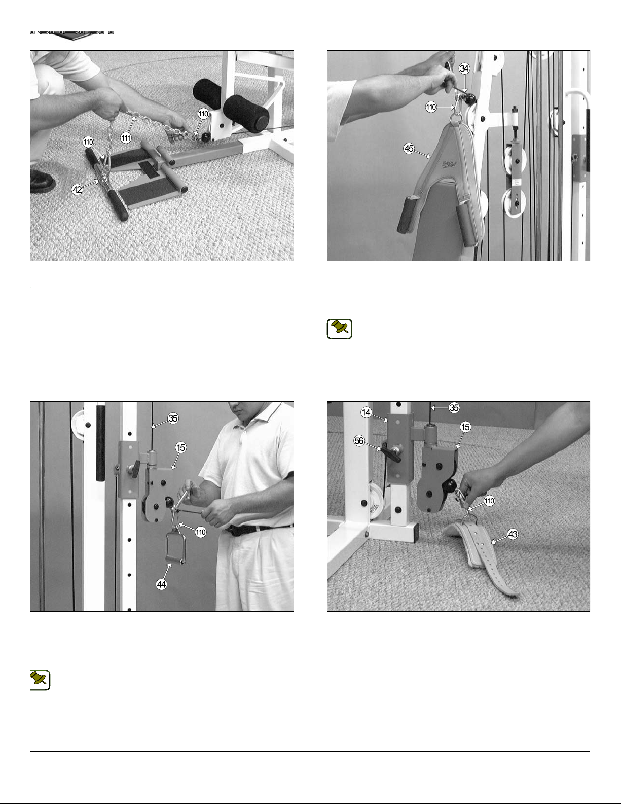
IG. 59 Locate the Coil Chain 3/16 X 21 (#111), two Snap Links (#110)
n
e
s
a
4
h
m
nd attach them to the Low Row Bar 20” (#42) and to the Leg
xtension/ Abdominal Cable (#34), as shown above.
FIG. 60 Affix the Abdominal Crunch Harness (#45) to the Leg Exte
sion/Abdominal Cable (#34) using one Snap Link (#110), one Should
Bolt 3/8 x 3/4 (#106), and one Nylon Insert Lock Nut 5/16-18 (#94). Us
the supplied Hex Key 3/16” (#114) and a 1/2” combination wrench to fa
ten this assembly properly.
Note: Refer to the Leg Extension/Abdominal Cable Mapping Di
gram on page 25 for further illustration of this assembly.
NOTE:
IG. 61 Affix the Chrome Stirrup Handle (#44) to the High-Low Cable
35) using one Snap Link (#110), one Shoulder Bolt 3/8 x 3/4 (#106), and
ne Nylon Insert Lock Nut 5/16-18 (#94). Use the supplied Hex Key
16” (#114) and a 1/2” combination wrench to fasten this assembly prop-
rly.
FIG. 62 The Leather Ankle Strap (#43) is another accessory that ca
be used at the High-Low Station. Adjust the High-Low Carriage (#1
to the first Adjustment setting, as shown above, then connect the Hig
Low Cable (#35) to the Leather Ankle Strap (#43) using the Snap Lin
(#110).
Note: Refer to the High-Low Cable Mapping Diagram on page 26
for further illustration of this assembly.
NOTE:
21 TS-1000 Home Gym w/Adjustable High-Low Pulley Syste
Page 23
TS-1000 CABLE ADJUSTMENT DIAGRAM
e
f
d
o
e
n
2
t
7
h
e
m
he Diagram below depicts the location of the cable adjustments on
ach work station. It is imperative that you maintain the cables’ proper
djustment to ensure a safe and smooth operation.
Cables should be inspected and adjusted periodically to avoid any
slack in the cables which would, consequently, prevent any damage to the equipment or personal injury.
CAUTION
Cable Adjustment for:
Adjustable Pulley Bracket (#27)
1. Loosen the bottom Regular Hex Nut (#90).
2. Adjust the top Nylon Insert Lock (#91) to give th
cable proper tension.
3. Re-tighten the bottom Regular Hex Nut (#90) t
complete the cable adjustment.
Adjustment for:
Long Adjustable Stopper (#28)
1. Loosen the two Regular Hex Nuts (#90).
2. Twist the Long Adjustable Stopper (#28) to le
or right until it is making contact with the Close
End Adj. Double Pulley Bracket (#30).
3. Re-tighten the Regular Hex Nuts (#90) t
complete the adjustment.
Adjustment for:
Short Adjustable Stopper (#29)
1. Loosen the Regular Hex Nut (#90).
2. Twist the Short Adjustable Stopper (#29)
to left or right until it is making contact with
the Closed-End Double Pulley Bracket
(#31).
3. Re-tighten the Regular Hex Nut (#90) to
complete the adjustment.
Cable Adjustment for:
Closed-End Adj. Double
Pulley Bracket (#30)
1. Remove the hardware from the Nylon Pulley 4 1/
Rd. (#67-Labeled D1).
2. By interchanging the Nylon Pulley 4 1/2 Rd. (#6
to the next adjustment hole it will make one inc
cable adjustment.
3. Re-tighten the hardware for the Nylon Pulley 4 1/
Rd. (#67) to complete the cable adjustment.
Cable Adjustment for:
Leg Extension/Abdominal Cable
(#36)
1. Loosen the Regular Hex Nut (#90).
2. Thread the Hex Tap Bolt 1/2-13 x 3 (#84) in
out of the threaded socket of the Floating Doubl
Pulley Bracket (#32) to give the Leg Extensio
Abdominal Cable (#38) proper tension.
3. Re-tighten the Regular Hex Nut (#90) to complet
the adjustment.
Caution: Make sure the Hex Tap Bolt 1/
13 x 3 (#84) is threaded at least 1/2” into th
threaded socket of the Floating Doubl
CAUTION
Pulley Bracket (#32) once the cable adjus
ment is complete.
S-1000 Home Gym w/Adjustable High-Low Pulley System
FULLY FASTEN
Fully Fasten: Proceed to Fully Fasten thes
hardware assemblies and all of the previous asse
blies that were left loosely fastened.
22
Page 24
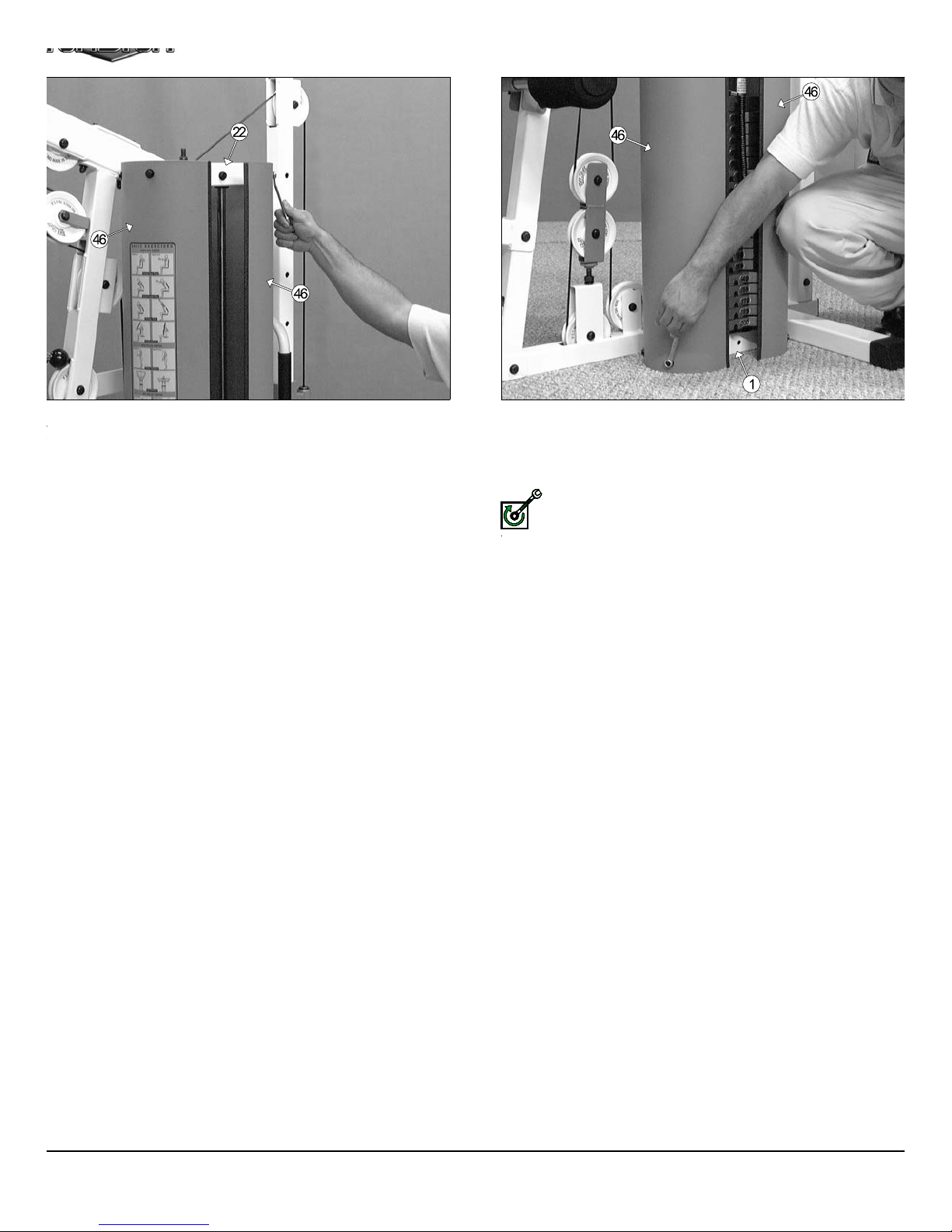
IG. 65 Once you have adjusted the cables according to the Cable
a
a
s
m
FULLY FASTEN
djustment Diagram on the previous page, then locate the two Weight
hrouds (#46) and affix them to the Guide Rod Retainer Housing’s
20) U-Nuts 1/4” (#81-Not shown) using four Hex Head Cap Screws 1/4-
X 3/4 (#105), and four Nylon Flat Washers 1/4” (#78). Refer to the Ex-
loded View Diagram on Fold out page for further illustration of this as-
mbly.
FIG. 66 Next, affix the bottom of the two Weight Shrouds (#46) to th
Base Frame’s (#1) U-Nuts 1/4” (#81-Not shown) using four Hex He
Cap Screws 1/4-20 X 3/4 (#105), and four Nylon Flat W ashers 1/4” (#89
Refer to the Exploded View Diagram on Fold out page for further illustr
tion of this assembly.
Fully Fasten:Proceed to align and fully fasten these hardware a
semblies.
23 TS-1000 Home Gym w/Adjustable High-Low Pulley Syste
Page 25
FIG. A
CABLE MAPPING DIAGRAM FOR:
Lat Cable #33
FIG. B
S-1000 Home Gym w/Adjustable High-Low Pulley System
24
Page 26

m
CABLE MAPPING DIAGRAM FOR:
Leg Extension/Abdominal Cable #34
FIG. C
25 TS-1000 Home Gym w/Adjustable High-Low Pulley Syste
Page 27
CABLE
MAPPING
DIAGRAM
FOR:
FIG. E
FIG. D
High-Low Cable #35
S-1000 Home Gym w/Adjustable High-Low Pulley System
26
Page 28

m
CABLE MAPPING DIAGRAM FOR:
Tension Cable #36
27 TS-1000 Home Gym w/Adjustable High-Low Pulley Syste
Page 29

CABLE MAPPING DIAGRAM
Right Side View
S-1000 Home Gym w/Adjustable High-Low Pulley System
28
Page 30

CABLE MAPPING DIAGRAM
m
Left Side View
29 TS-1000 Home Gym w/Adjustable High-Low Pulley Syste
Page 31

1
4
1
2
4
6
2
2
2
2
9
1
1
5
4
6
1
1
8
1
8
5
1
1
1
1
8
2
8
5
1
8
3
5
3
1
4
2
1
5
7
2
3
3
8
5
4
4
2
5
1
2
1
1
1
2
1
2
1
1
LOR CHART
m
AY= SUB-ASSEMBLY PARTS
ACK= HARDWARE
TS-1000 PARTS LIST
m No.
1 BASE FRAME UP726 1 61 RUBBER GRIP 1 1/ 4 X 10 BNH0948
2 LOW ROW STABILIZER UP727 1 62 RUBBER GRIP 1 X 6-1/ 4 BNH0296
3 LOW ROW FOOT SUPPORT UP728 1 63 RUBBER GRIP 1/ 2 X 4 BNH0530
4 FOOT ROLL TUBE 1 X 16 UP053 3 64 RUBBER DONUT 3/ 4 X 2 1/ 2 BNH0068
5 REAR UPRIGHT UP729 1 65 ANTI-SKID TAPE 4 X 7 3/ 4 BNH0492
6 FRONT UPRIGHT UP730 1 66 FOAM FOOT ROLL 7 X 4 X 1 BNH0043
7 ADJUSTABLE BACK PAD BRACKET UP554 1 67 NYLON PULLEY 4 1/ 2 RD BNH0556
8 CABLE RETAINER BRACKET L-SHAPED UP014 1 68 NYLON PULLEY 3 1/ 2 RD BNH0553
9 LEG EXTENSION BENCH FRAME UP555 1 69 PLASTIC END CAP W/ GROOVE 2 X 3 BNH0049
10 LEG EXTENSION ARM UP325 1 70 PLASTIC END CAP 2" SQ W/ GROOVE BNH0051
11 LEG EXTENSION AXLE 1/ 2 X 2 3/ 4 UP373 1 71 PLASTIC INSERT CAP 2" SQ BNH0012
12 T OP PULLEY ASSEMBLY UP731 1 72 PLASTIC INSERT CAP 1 1/ 2 SQ BNH0009
13 HIGH/ LOW SELECTORIZED UPRIGHT UP732 1 73 PLASTIC INSERT CAP 1 X 2 BNH0005
14 HIGH/ LOW CARRIAGE UP733 1 74 PLASTIC INSERT CAP 1 1/ 4 RD BNH0573
15 HIGH LOW DOUBLE PULLEY BRACKET UP734 1 75 PLASTIC INSERT CAP 1 RD BNH0002
16 GUIDE ROD 3/ 4 X 72 UP124 2 76 FOOT ROLL PLASTIC END CAP 1" BNH0397
17 15 LB WEIGHT PLATE BNH0926 5 77 RUBBER BUMPER 3/ 8 X 1 1/ 2 BNH0514
18 10 LB WEIGHT PLATE BNH0904 9 78 PLA STIC INSERT CAP 2 X 3 BNH0052
19 5 LB WEIGHT PLATE BNH0927 5 79 NYLON STEM BUTTON 12.5 mm BNH0547
20 TOP PLATE/ SELECTOR BAR BNH0876 1 80 RETAINING SNAP RING BNH0419
21 SELECTOR PIN W/ COIL UP466 181U NUT 1/ 4" BNH0708
22 GUIDE ROD RETAINER HOUSING UP328 1 82 SPLIT WASHER B/ O 1/ 2" BNH0653
23 PRESS BAR SELECTOR HOUSING UP681 1 83 SPLIT WASHER Z/ P 1/ 2" BNH0572
24 PIVOT AXLE 1 X 8 1/ 8 UP152 2 84 H EX TAP BOLT W/ 1/ 4 HOLE 1/ 2-13 X 3 BNH1088
25 PRESS BAR UP742 1 85 SPLIT BOLT 1/ 2-13 X 1 BNH0479
26 LAT BAR HOLDER 2 X 3 UP327 1 86 FLAT WASHER SAE 1/ 2" BNH0238
27 ADJUSTAB LE P ULLEY BRACKET UP368 1 87 FLAT WASHER SAE 3/ 8" BNH0239
28 LONG ADJUSTABLE ST OPPER UP331 1 88 NYLON FLAT WASHER 3/ 8 BNH0248
29 SHORT ADJUSTABLE ST OPPER UP735 1 89 NYLON FLAT WASHER 1/ 4 BNH0889
30 CLOSED-END ADJ. DOUBLE PULLEY BRACKET UP689 1 90 REGULAR HEX NUT 1/ 2-13 BNH0201
31 CLOSED-END DOUBLE PULLEY BRACKET UP736 1 91 NYLON INSERT LOCK NUT 1/ 2-13 BNH0212
32 FLOATING DOUBLE PULLLEY BRACKET UP737 2 92 NYLON INSERT LOCK NUT 3/ 8-16 BNH0214
33 LAT CABLE UP738 1 93 NYLON INSERT JAM LOCK NUT 3/ 8-16 BNH0365
34 LEG EXTENSION / ABDOMINAL CABLE UP739 1 94 NYLON INSERT LOCK NUT 5/ 16-18 BNH0215
35 HIGH/ LOW CABLE UP740 1 95 NYLON INSERT LOCK NUT 1/ 4-20 BNH0213
36 TENSION CABLE UP741 1 96 HEX HEAD CAP SCREW 3/ 8-16 X 4 1/ 2 BNH0284
37 ADJUSTABLE SEAT FRAME UP171 1 97 HEX HEAD CAP SCREW 3/ 8-16 X 4 1/ 4 BNH0317
38 FOOT ROLL TUBE 1 X 27 UP743 1 98 HEX HEAD CAP SCREW 3/ 8-16 X 4 BNH0285
39 BENCH PRESS BACK PAD UP744 1 99 HEX HEAD CAP SCREW 3/ 8-16 X 3 1/ 4 BNH0312
40 SEAT PAD UP173 1 100 HEX HEAD CAP SCREW 3/ 8-16 X 2 3/ 4 BNH0278
41 LAT BAR 48" BNH0295 1 101 HEX HEAD CAP SCREW 3/ 8-16 X 2 1/ 2 BNH0276
42 LOW ROW BAR 20" BNH0294 1 102 HEX HEAD CAP SCREW 3/ 8-16 X 1 3/ 4 BNH0274
43 LEATHER ANKLE STRAP 20000-ALAS 1 103 HEX HEAD CAP SCREW 3/ 8-16 X 1 1/ 4 BNH0273
44 CHROME STIRRUP HANDLE 20000-SH 1 104 HEX HEAD CAP SCREW 1/ 4-20 X 1 1/ 2 BNH0272
45 ABDOMINAL CRUNCH HARNESS BNH0235 1 105 HEX HEAD CAP SCREW 1/ 4-20 X 3/ 4 BNH0890
46 WEIGHT SHROUD UP332 2 106 SHOULDER BOLT 3/ 8 X 3 / 4 BNH0718
47 DECAL- EXERCISE CHART (FRONT) BNH1090 1 107 STRAP BRACKET #20 BNH0562
48 "L" LOCKING PIN BNH0045 1 108 NYLON BALL 1 3/ 4 X 5/ 16 BNH0392
49 EDGE PROTECTOR 72 1/ 4" BNH0587 4 109 NYLON SPACER 3/ 8 X 3/ 8 BNH0392
50 METAL HINGE BNH0046 2 110 SNAP LINK BNH0065
51 SE T SCREW 3/ 8-16 X 1/ 2 BNH0474 5 111 COIL CHAIN 3/ 16 X 21 BNH0017
52 SE T SCREW 1/ 4-20 X 3/ 8 BNH0772 2 112 HEX HEAD CAP SCREW 3/ 8-16 X 3 BNH0282
53 SE T SCREW 1/ 4-20 X 1/ 4 BNH0790 2 113 STANDARD DECAL WEIGHT NUMBERS BNH0928
54 BRONZE BUSHING 1 X 1 1/ 4 BNH0527 6 114 HEX KEY 3/ 16" BNH0371
55 BRONZE BUSHING 1/ 2 X 5/ 8 BNH0528 2 115 HEX KEY 1/ 8" BNH0767
56 PUSH-PULL PIN 1/ 2" X 3-1/2 BNH0520 2 116 RUBBER GROMMET 3/ 4" ID BNH0401
57 TURN/ PULL PIN W/ KNOB BNH0929 1 117 PLASTIC TUBE END 1 X 1-1/ 4 X 3/ 8 BNH1089
58 PUSH-PULL PIN 1/ 2" X 5-5/8 BNH0586 1 118 BRONZE BUSHING 3/ 8 X 1/ 2 X 1/ 2 BNH0738
59 RUBBER STOPPER 1 X 3 BNH0791 2 119 RUBBER ST OPPER 1/ 8 X 1 1/ 2 X 5 BNH0688
60 RUBBER GRIP 1 1/ 4 X 5 1/ 4 BNH0937 4 120 DECAL- EXERCISE CHART (REAR) BNH1092
Descr i ption Part No.
Qty Item No.
Descr i ption Part No.
Qt
31 TS-1000 Home Gym w/Adjustable High-Low Pulley Syste
Page 32
Adj
/
a
3
e
4
/
/
e
w
ustment Features
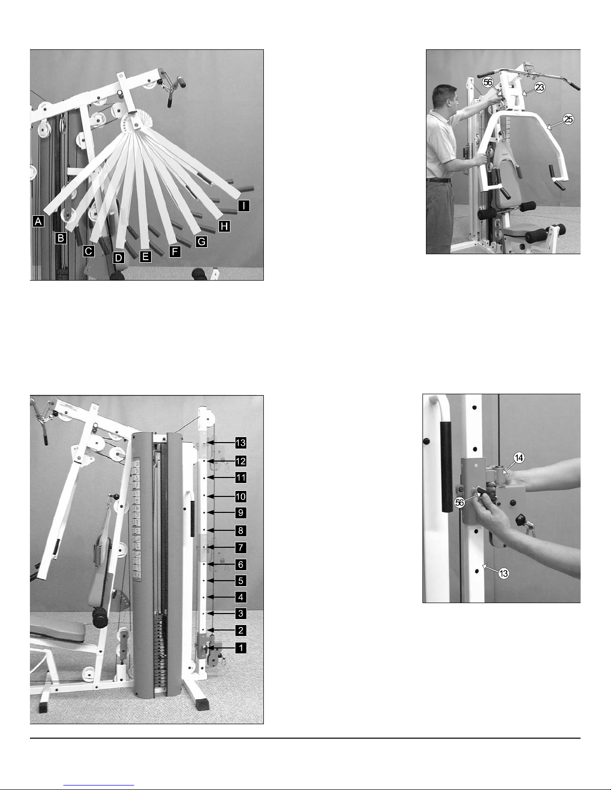
Press Bar Range of Adjustable
Settings
♦ Used for Seated Row
Exercise.
Setting A - C
♦ Used for Chest Press
Exercise.
Setting D - F
♦ Used for Shoulder Press
Exercise.
Setting G - I
Fig. 68 Press Bar (#25) adjustment:
ig. 67 Illustration of the Press Bar’s adjustable settings
sed on multiple Exercise Starting Positions.
Fig. 69 Illustration of the High-Low
Carriage’s adjustable settings used
on multiple Exercise Starting Positions.
1. Grasp the Press Bar (#25).
2. Pull the Push Pull Pin 1/2” X 3-1
(#56) to release the Press B
(#23).
3. Adjust the Press Bar (#25) to th
desired position.
4. Release the Push Pull Pin 1/2” X
1/2 (#56) and make sure it full
engages into the selected hole of th
Press Bar’s (#25) Plate.
S-1000 Home Gym w/Adjustable High-Low Pulley System
Fig. 70 High-Low Carriage (#1
1. Grasp the Carriage (#14).
2. Pull the Push Pull Pin 1/2” X 3-1
3. Adjust the Carriage (#14) to th
4. Release the Push Pull Pin 1/2” X 3-1
adjustment:
(#56) to release the Carriage (#14).
desired position.
(#56) and make sure it fully engag
into the selected hole of the High-Lo
Selectorized Upright (#13).
33
Page 33
e
7
Adj
a
o
g
h
w
m
ustment Features
ig. 71 Back Pad (#39) adjustment:
. Grasp the Back Pad (#39).
. Pull the Push Pull Pin 1/2” X 5-5/8 (#58) to release the Back Pad
Bracket (#7) from the Front Upright (#6).
.Adjust the Back Pad (#39) to one of the seven available positions.
. Release the Push Pull Pin 1/2” X 5-5/8 (#58) and make sure it fully
engages into the selected hole of the Back Pad Bracket (#7).
Fig. 72 Seat Pad (#40) adjustment:
1. Grasp the Seat Pad (#40).
2. Turn counterclockwise then pull the Turn/Pull Pin w/Knob (#57) to releas
the Adjustable Seat Frame (#37) from the Leg Extension Bench Fram
(#9).
3. Adjust the Seat Pad (#40) to a desired height.
4. Release the Turn/Pull Pin w/Knob (#57) and make sure it fully engag
into the selected hole of the Adjustable Seat Frame (#37).
5. Complete the adjustment by turning the Turn/Pull Pin w/Knob (#5
clockwise.
ig. 73 Locking the Leg Extension Arm (#10)
. Locate the L-Locking Pin (#48).
. Insert the L-Locking Pin (#48) through the Leg Extension Bench
Frame (#9) and the Leg Extension Arm (#10), as shown above.
Unlocked
Locked
Leg Extension Arm used on Exercises:
Leg Extension
Leg Curl
Leg Extension Arm used on Exercises:
Low Row
Standing Arm Curl
Seated Row
Seated Chest Press
Seated Shoulder Press
Fig. 74 Positioning the Low Row Foot Support (#3)
1. Picture above at the left shows the Low Row Foot Support (#3) pos
tioned and ready for Standing Arm Curl Exercise. It is IMPORTANT th
when in this position, you must stand completely on the Low Row Fo
Support (#3) and not off. This is done to prevent the unit from tippin
during this workout exercise.
2. Picture above at the right shows the Low Row Foot Support (#3) pos
tioned and ready for the Seated Rowing Exercise.
Note: Do not drop the Low Row Foot Support (#3) or leave it in t
position as pictured above at the right. Always lower the Low Ro
NOTE:
Foot Support (#3) when not in use.
34 TS-1000 Home Gym w/Adjustable High-Low Pulley Syste
Page 34
Maintenance
.
d
M aintenance Information
1. Lubrication of all moving parts is essential to the longevity
and optimal performance of your Home Gym. Initial
lubrication of some parts of your gym have been done at
the factory, but the weight stack guide rods must be
lubricated at the time of assembly. We recommend a
clear aerosol, silicone or teflon spray.
Note: Do not use oil based lubricants as they will attract
dust,dirt and grime, and will eventually gum up and erode
bushings and sealed bearings.
2. All pulleys and bushings should be checked regularly for
signs of wear.
Correct
3. Check and adjust cable tension periodically as it will
maintain proper anatomical function.
4. Periodically check all moving parts, upholstery and grips
for signs of wear or damage. If there is a problem or
replacement part is necessary, STOP USING THE
EQUIPMENT and immediately contact your local Tuff Stuff
retailer or call our Customer Service Department. Replace
parts using only genuine Tuff Stuff parts.
5. As needed, upholstery may be cleaned with a mild
solution of soap and water. Regular use of a vinyl
treatment will add to the life and appearance of your
upholstery.
6. All chrome plated surfaces should be cleaned regularly to
prolong the life and luster of the finish. Wipe machine
down with a damp cloth and dry thoroughly each day. At
least once a week your chrome equipment should be
polished with a commercial grade or automotive type
chrome polish.
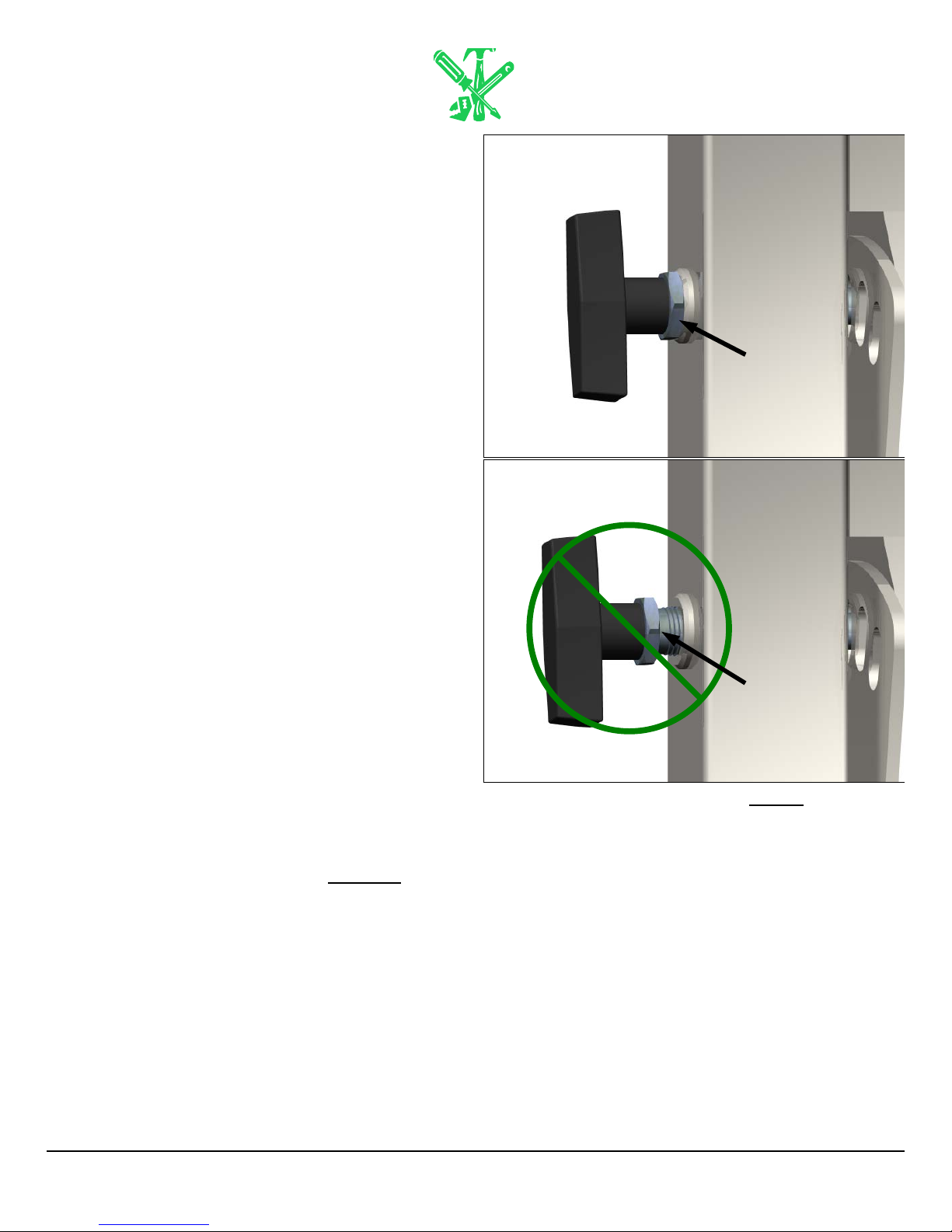
7. When checking the bolts and nuts, be sure they are all
fully fastened. If there is a bolt or nut that continuously
loosens obtain a replacement through your local Tuff Stuff
retailer or call our Customer Service Department.
Push Pull Pin
Hex Nut
Fully Fastened.
Incorrect
Push Pull Pin
Hex Nut
Loosely Fastened
Fig. 75 Caution: Be sure the Push Pull Pin Hex nuts are fully fastene
Fasten if necessary.
8. Check that the Push Pull Pins 1/2 X 3-1/2 (#56), and the
Push Pull Pin 1/2 x 5-5/8 (#58) Hex Nuts
fastened (See Fig. 75). In addition, be sure the springs in
the Push Pull Pins are operating freely.
9. Check welds to be free of cracks.
10. Failure to perform routine maintenance could result in
personal injury and/or equipment damage.
S-1000 Home Gym w/Adjustable High-Low Pulley System
are fully
35
Page 35

DO NOT DISCARD THIS MANUAL
HOME LIFETIME WARRANTY
TuffStuff products are warranted to the retail purchaser to be free from defects in materials and workmanship.
TuffStuff exclusive Home Lifetime Warranty coverage extends for the life of the product while owned by the
original retail purchaser, and used only in a home or residential setting unless otherwise noted in the owner’s
manual.
This warranty does not cover:
1. TuffStuff products sold for and used in a commercial or institutional setting.
2. Any damage, failure or loss caused by accident, misuse, neglect, abuse, improper assembly, improper
maintenance, or failure to follow instructions or warnings in the owner’s manual and warning labels
posted on the machine.
3. Use of products in a manner for which they were not designed.
4. Original product that is altered, or the use of replacement parts and components of another manufacturer other than TuffStuff.
Limitations:
The foregoing shall constitute the sole remedy of the purchaser and the sole liability of TuffStuff with regard to
warranty, whether express or implied by operation of law or otherwise, including but not limited to any implied
warranties of merchantability or fitness. TuffStuff shall in no event be liable for incidental or consequential
losses, damages or expenses in connection with exercise products. TuffStuff’s liability hereunder is expressly
limited to the repairs or replacements of warranted defective parts.
Procedures:
Warranty service will be performed at TuffStuff’s facility in Pomona, California. TuffStuff will have the option of
either repair or replacement at no charge for any defective product. Purchaser is responsible for installation of
repaired or replaced parts and all transportation and insurance costs on returned or replaced equipment to and
from TuffStuff’s facility in Pomona.
This warranty gives you specific legal rights and you may also have other rights, which may vary from state to
state. Effective July 1, 2004.
This warranty is the final, complete and exclusive agreement of the parties with respect to the quality or performance of the equipment
and no action for breach of this written warranty or any implied warranty shall be commenced more than one (1) year after the accrual
of the cause of action. No modification of this warranty or waiver of its terms shall be binding on either party unless approved in
writing by an authorized representative of the party. Contact TuffStuff at 1325 E. Franklin Avenue, Pomona, California 91766, before
returning any defective equipment.
Note: Retain your sales receipt and be sure to mail in the warranty registration card to insure that a
permanent record of your purchase is on file with the factory and to avoid unnecessary delays in
warranty service.
TASK INDUSTRIES, INC.
1325 E. Franklin Ave., Pomona, CA 91766
Ph: 909-629-1600 Fax: 909-629-4967
E-mail: service@tuffstuff.net Net: www.tuffstuff.net
 Loading...