

Page 1

A SSEMBLY INSTRUCTION MAN UAL
START
FINISH
LEG PRESS
Revision Date 12-98
TG-11L
Leg Press (Option)
L 8’-7” W 6’-6” H 7’ -0”
Foot Print Shown Above with TG-150
L 8’-7” W 6’-6” H 7’ -0”
Foot Print Shown Above with TG-250
A merica’s Premium Exercise Equipment
Page 2
Introduction
About the Leg Press (TG-11L)
Congratulations on your new purchase of the Leg Press (TG-11L) . We
hope you are completely satisfied with this product and wish you many
years of enjoyment.
Tuff Stuff Equipment
Every Tuffstuff product has been built to precise quality standards and
has been carefully packaged to ensure that damage will not occur during
shipment. The limited lifetime warranty and signature indicating final
inspection has been conducted by our line foreman, is an expression of our
confidence in the completeness, the materials, and workmanship of this
product.
Warranty
SEE WARRANTY REGISTRATION CARD
Registration Card
To avoid unnecessary delays in warranty service and to insure that a
permanent record of your purchase is on file with our factory, be sure to
complete the warranty registration card and send it to Task Industries today.
Safety Information
1) Familiarize yourself and others with the proper operation and workout
recommendations for each piece of Tuff Stuff equipment prior to use.
2) Consult with your physician before beginning any exercise program.
3) Use proper discretion when children are present.
4) Inspect machine for any sign of parts or hardware becoming loose.
5) Periodically check the cable for any indication of wear.
6) Keep hands and limbs clear from weight stack and all
other moving parts.
Maintenance Information
1) Lubrication of the axles is essential to the longevity and optimal
performance of your TG-11L Leg Press. We recommend a multi-purpose
grease for this application.
2) All cables and bushings should be checked regularly for signs of wear.
3) Periodically check all moving parts, upholstery and grips for wear. If
replacement is necessary, please contact your local Tuff Stuff retailer or call
our Customer Service Department.
4) As needed, upholstery may be cleaned with a mild solution of soap and
water. Regular use of a vinyl treatment will add to the life and appearance of
your upholstery.
Tool Requirements
1) Two 3/4” Open-end wrenches
2) Two 9/16” Open -end wrenches
3) One rubber mallet hammer
4) Multi- Purpose Grease
5) Hex Key 3/16 (Supplied)
6) Measuring tape
Hardware Measurement Diagram
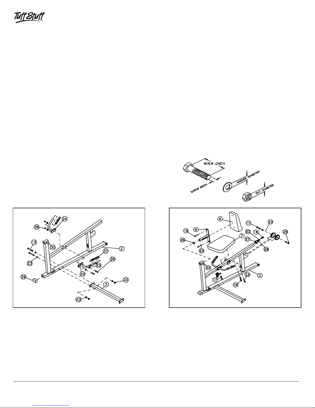
FIG. 1 Start by mounting the Stabilizer Support (#3) onto the Main
Frame (#2) and secure it into place using two Hex Head Cap Screws 3/8-
16 X 3 3/4 (#15), four Flat Washers SAE 3/8 (#23) and two Nylon Insert
Jam Lock Nuts 3/8-16 (#25). Next, attach the Handle Rt. (#33) and the
Handle Lt. (#34) to the Main Frame (#2) and secure them into place
using two Hex Head Cap Screw 3/8-16 X 3 1/4 (#35), four Flat Washers
SAE 3/8 (# 23) and two Regular Nylon Insert Lock Nut 3/8-16 (#36). Next,
insert two Hard Grips .875 X 8 (#37) over the tube ends of the Handle Rt .
(#33) and the Handle Lt. (#34). Note: It is recommended to use windex
or a household glass cleaner for easy insertion of the Hard
Grips .875 X 8 (#37) . Next, insert one Plastic End Cap w/Groove 2 X 3
(#29) onto the tube end of the Main Frame (#2).
1
1
FIG. 2 Next, mount the Back Pad (#6) onto the Adjustable Back
Pad Tube (#8) and secure it into place using two Hex Head Cap
Screws 3/8-16 X 1 (#19) and two Flat Washers SAE 3/8 (#23). Next,
insert one Plastic Insert Cap 1 3/4 Sq. (#26) into the Adjustable Back
Pad Tube (#8),as shown above. Next, attach the Seat Pad (#7) to the
Main Frame (#2) and secure it into place using two Hex Head Cap
Screws 3/8-16 X 1 (#19), one Hex Head Cap Screw 3/8-16 X 2 3/4
(#17-Labeled with arrow) and three Flat Washers SAE (#23). Next,
attach two Nylon Pulleys 4 1/2” Rd. (#30) into the front pulley bracket
of the Main Frame (#2). Secure them into place using one Hex Head
Cap Screw 3/8-16 X 2 3/4 (#17), two Flat Washers SAE 3/8 (#23) and
one Nylon Insert Jam Lock Nut 3/8-16 (#25). Next, mount the Rubber
Bumper (#27) onto the Main Frame (#2) and secure it into place using
one Hex Head Cap Screw 3/8-16 X 1 3/4 (#18),one Steel Washer 3/8
(#28) and one Flat Washer SAE 3/8 (#23).
TG - 11L Leg Press
TG-11L Leg Press (Option)
Page 3
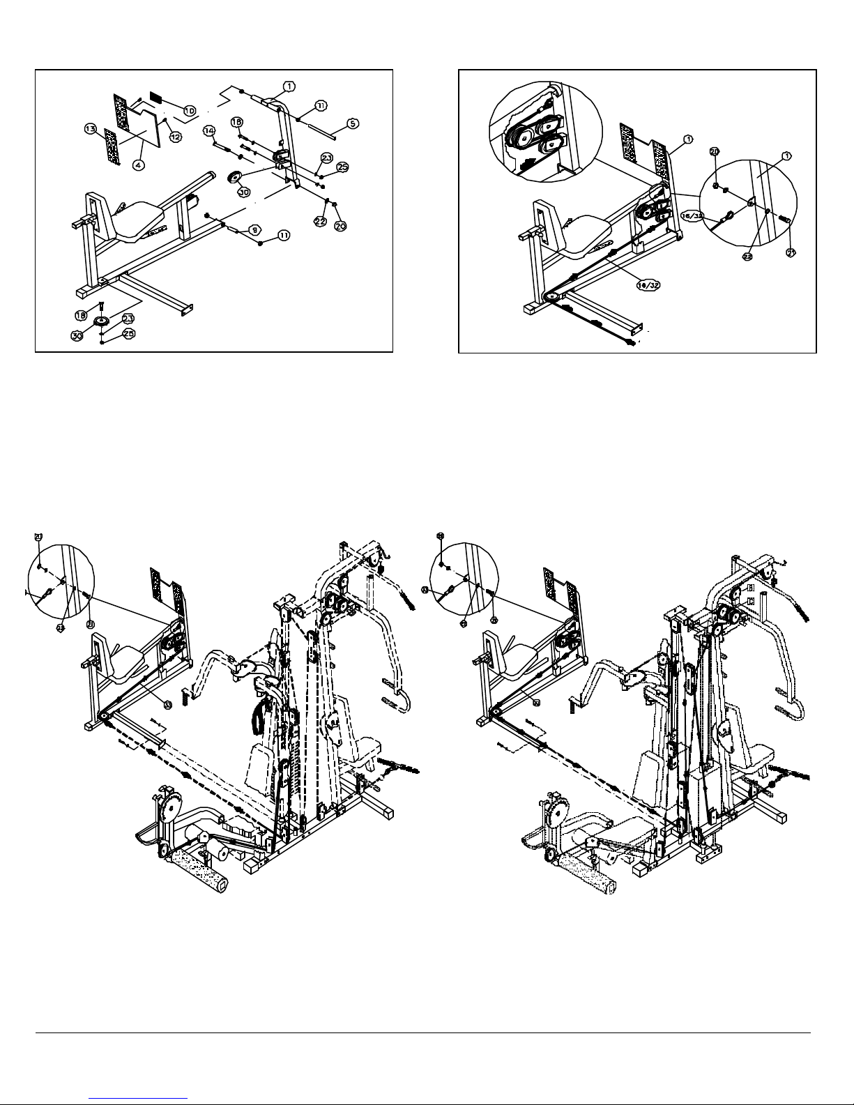
FIG. 2 Attach three Nylon Pulleys 4 1/2 Rd. (#30) ,as shown above.
250, as shown above, and
16 X 3 3/4 (#15),
Main
Labeled
will replace the existing cable you are using for the
Labeled with
will now be used for the Low Row and the Leg Press
Attach two of the Nylon Pulleys 4 1/2 Rd. (#30) to the brackets located
on the Fulcrum (#1) and then one on the Main Frame (#2). Secure all
Nylon Pulleys 4 1/2 Rd. (#30) into place using three Hex Head Cap
Screws 3/8-16 X 1 3/4 (#18), six Flat Washers SAE 3/8 (#23) and three
Nylon Insert Jam Lock Nuts 3/8-16 (#25). Next, insert the Small Axle
(#9) into the Main Frame (#2) . Then mount the Fulcrum (#1) onto the
front of the Main Frame (#2) and secure it into place using one Hex
Head Cap Screw 1/2-13 X 5 1/2 (#14), two Flat Washers SAE 1/2 (#22)
and one Nylon Insert Jam Lock Nut 1/2-13 (#20) . Next, insert the Foot
Plate (#4) onto the Fulcrum (#1), as shown above, with the Large Axle
(#5) and secure it into place using two Set Screws 3/8-16 X 1/2 (#12).
Note: It is recommended to lubricate the axles using a multi-purpose
Owners’ Manual: Assembly Instructions
Note: Some Parts Not
Shown or cut away for
clarity
Fig. 3 Note: Before routing the cable, locate the Main Cable (#16-
Labeled with tape TG-150) or the Main Cable (#31-Labeled with
tape TG-250). The label on the cable will determine which cable is
needed for either the TG-150 or the TG -250. Route the Main Cable
(#31 or #16), as illustrated above, beginning at the TG-150 or TG-250
and finishing at the Fulcrum (#1) mounting bracket. Secure the Main
Cable (#31 or #16) to the Fulcrum (#1) mounting bracket using one
Hex Head Cap Screw 1/2-13 X 1 (#21), two Flat Washers SAE 1/2
(#22) and one Nylon Insert Jam Lock Nut 1/2-13 (#20). Note: Use Fig.
A and Fig. B and your TG-150 Or TG-250 Instruction Manual for
further clarification of the this cable routing.
Fig. A
TG-11L to TG-150
Cable Routing Diagram
FIG. A Attach the TG-11L to the TG-150, as shown above, and
secure it into using two Hex Head Cap Screws 3/8-16 X 3 3/4 (#15), four
Flat Washers SAE 3/8 (#23) and two Nylon Insert Jam Lock Nuts 3/8-16
(#25). When installing the TG-11L you will receive a new cable, the Main
Cable (#16-Labeled with tape TG-150). This Main Cable (#16-Labeled
with tape TG-150) will replace the existing cable you are using for the
Leg Extension station on the TG-150. This new Main Cable (#16-Labeled
with tape TG-150) will now be used for the Leg Extension and the Leg
Fig. B
TG-11L to TG-250
Cable Routing Diagram
FIG. B Attach the TG-11L to the TG-
secure it into place using two Hex Head Cap Screws 3/8four Flat Washers SAE 3/8 (#23) and two Nylon Insert Jam Lock Nuts 3/8
16 (#25). When installing the TG-11L you will receive a new cable,
Cable (#31-Labeled with tape TG-250). This Main Cable (#31with tape TG-250)
Low Row station on the TG-250. This new Main Cable (#31-
tape TG-250)
TG-11L Leg Press (Option)
2
Page 4

DO NOT DISCARD THIS MANUAL
TG-11L PARTS LIST
1
FULCRUM
UP156
120NYLON INSERT JAM LOCK NUT 1/2-13
BNH0366
2
2
MAIN FRAME
UP170
1
21
HEX HEAD CAP SCREW 1/2-13 X 1
BNH0259
13STABILIZER SUPPORT
UP157
122FLAT WASHER SAE 1/2"
BNH0238
4
4
FOOT PLATE
UP155
1
23
FLAT WASHER SAE 3/8"
BNH0239
28
6
BACK PAD
UP145
1
25
NYLON INSERT JAM LOCK NUT 3/8-16
BNH0365
10
26
PLASTIC INSERT CAP 1 3/4 SQ
BNH0053
1
8
ADJUSTABLE BACK PAD TUBE
UP136
1
27
RUBBER BUMPER 3/8 X 2 1/2
BNH0511
1
28
STEEL WASHER 3/8"
BNH0498
1
31
MAIN CABLE ( 250 )
TG11L-31-00
1
33
HANDLE (RT)
UP270
1
16
MAIN CABLE (150 )
TG11L-16-00
135HEX HEAD CAP SCREW 3/8-16 X 3 1/4
BNH0312
2
TG-11L EXPLODED VIEW DIAGRAM
COLOR CHART
GRAY= SUB-ASSEMBLY PARTS
BLACK= HARDWARE
Item No. Description Part No. Qty Item No. Description Part No. Qty
5 LARGE AXLE 1 X 10 3/8 UP154 1 24 HEX KEY 3/16" BNH0371 1
7 SEAT PAD UP146 1
9 SMALL AXLE 1 X 4 1/4 UP153 1
10 RUBBER MAT 2 1/2 X 3 1/2 BNH0688 1 29 PLASTIC END CAP W/GROOVE 2X 3 BNH0049 1
11 BRONZE BUSHING 1 X 1 1/4 BNH0527 4 30 WHITE NYLON PULLEY 4 1/2 RD BNH0506 6
12 SET SCREW 3/8-16 X 1/2 BNH0474 2
13 SAFETY TAPE 4 X 12 BNH0492 2 32 PUSH-PULL PIN 1/2 BNH0515 1
14 HEX HEAD CAP SCREW 1/2-13 X 5 1/2 BNH0267 1
15 HEX HEAD CAP SCREW 3/8-16 X 3 3/4 BNH0281 4
17 HEX HEAD CAP SCREW 3/8-16 X 2 3/4 BNH0278 2 36 NYLON INSERT LOCK NUT 3/8-16 BNH0214 2
18 HEX HEAD CAP SCREW 3/8-16 X 1 3/4 BNH0274 4 37 HARD GRIP .875 X 8 BNH0523 2
19 HEX HEAD CAP SCREW 3/8-16 X 1 BNH0275 4
34 HANDLE (LT) UP271 1
1325 E. Franklin Ave., Pomona, CA 91766
Ph: 909-629-1600 Fax: 909-629-4967
E-mail: taskind@aol.com Net: www.tuffstuff.com
 Loading...