

Page 1
OWNER’ S MANUAL
TABLE OF CONTENTS:
Introduction
Pg. 1
Safety Precautions
Pg. 2
Assembly Instructions
Pg. 3 - Pg. 14
Cable Adjustment Diagram
Pg. 15
Maintenance
Pg. 16
Parts List
Pg. 17
Exploded View Diagram
Pg. 18
Cable Mapping Diagram
Pg. 18
Warranty
Back Page
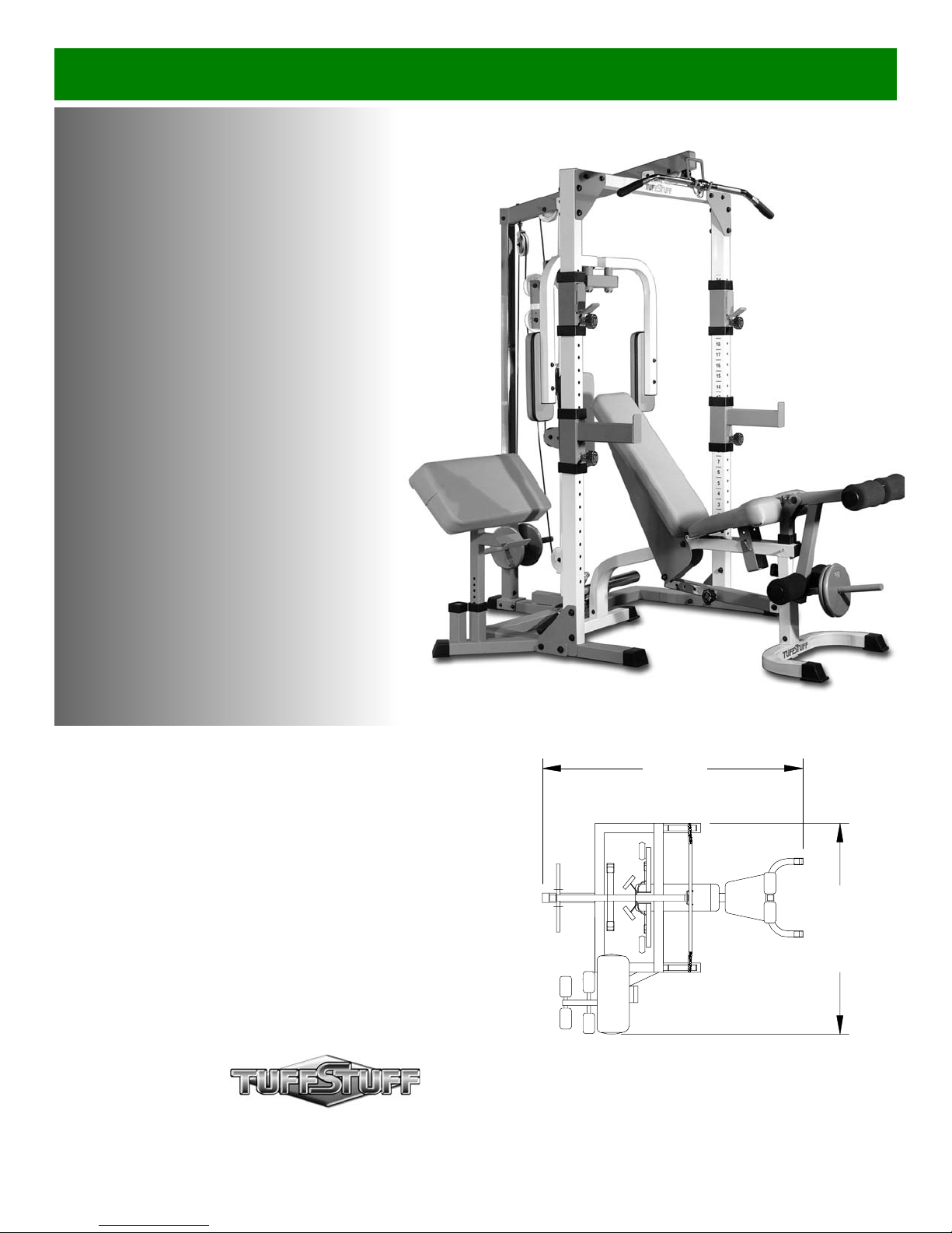
DH-345
alf Cage Ensemble
Revision Date 06-30-03
7’- 0”
5’- 8”
America’s Premium Exercise Equipment
L 7’- 0” W 5’- 8” H 7’- 0”
Page 2

Int
roduction
u
-
-
e
-
e
e
s
.
-
-
o
-
e
bout the TDH-345 Half Cage Ensemble
ongratulations on your new purchase of the TDH-345 Half
age Ensemble. This gym is capable of a variety of different
xercises, as well as, smooth and user-friendly adjustment fea-
res. In addition, this gym has been designed to meet the
eeds and performance requirements for a suitable home exer-
ise machine. We hope you are completely satisfied with this
roduct and wish you many years of enjoyment.
uff Stuff Equipment
his Tuffstuff product has been built to precise quality standards
nd has been carefully packaged to ensure that damage will not
ccur during shipment. The Home Lifetime Warranty and signa-
re indicating final inspection has been conducted by our line
reman, is an expression of our confidence in the complete-
ess, the materials, and workmanship of this product.
arranty
EE A COPY OF WARRANTY ON BACK PAGE.
egistration Card
o avoid unnecessary delays in warranty service and to insure
at a permanent record of your purchase is on file with our facry, be sure to complete the warranty registration card and
end it to Task Industries today.
pecifications
. Maximum Wt. Capacity - 600 Lbs.
. Total Machine Weight - 405 Lbs.
. Footprint (LWH) See Front Page
bout the Icons
he icons displayed in this Owner’s Manual are used to facilitate
he correct assembly and safe use of this Product, as-well-as to
revent injury to yourself or anyone else.
Note provides information necessary to properly
complete a procedure or information which will
make the procedure easier to understand.
Caution indicates a potentially hazardous situation, which, if not avoided, may result in minor or
moderate injury. It may also be used to alert
against unsafe practices.
Prior to the Assembly of the TDH-345
1. We advise you to consult your local Tuff Stuff retailer if yo
should have a question or problem regarding the proper as
sembly of this Half Cage Ensemble.
2. Consider the complete surface area of the Half-Cage Ensem
ble. Use the overhead view located on the front page for de
signing your layout before assembling. Once the Half-Cag
Ensemble has been fully assembled it will be heavy and diffi
cult to move. Therefore, you should, assemble the Half-Cag
Ensemble in the area where it is to be used upon completion.
3. It is recommended that another person assist you with th
assembly of this unit.
4. Neatly organize and identify all parts according to the Part
List on page 17, and the Exploded View Diagram on page 18
Assembly Notes
1. Read and follow each step of this Assembly Instruction Man
ual in sequence. Do not skip ahead, as it will result in an im
proper assembly or in having to disassemble parts later.
2. During the assembly of the this unit you will be instructed t
leave some Hex Head Cap Screws loosely fastened. Natu
rally, they will be fully fastened later in the assembly process
This is done to prevent any difficulty with alignment of som
parts during this assembly.
Tool Requirements
1.One 9/16” combination wrench
2.One 3/4” combination wrench
3.One 7/8” combination wrench
4.One 1/2” combination wrench
5.One ratchet
6.One 9/16” socket
7.One 3/4” socket
8.External retaining-ring pliers
9.One rubber mallet
10.One can silicone spray / teflon spray lubricant
11.Windex or household glass cleaner
12.Measuring tape
13.Utility knife
Hardware Measurement Diagram
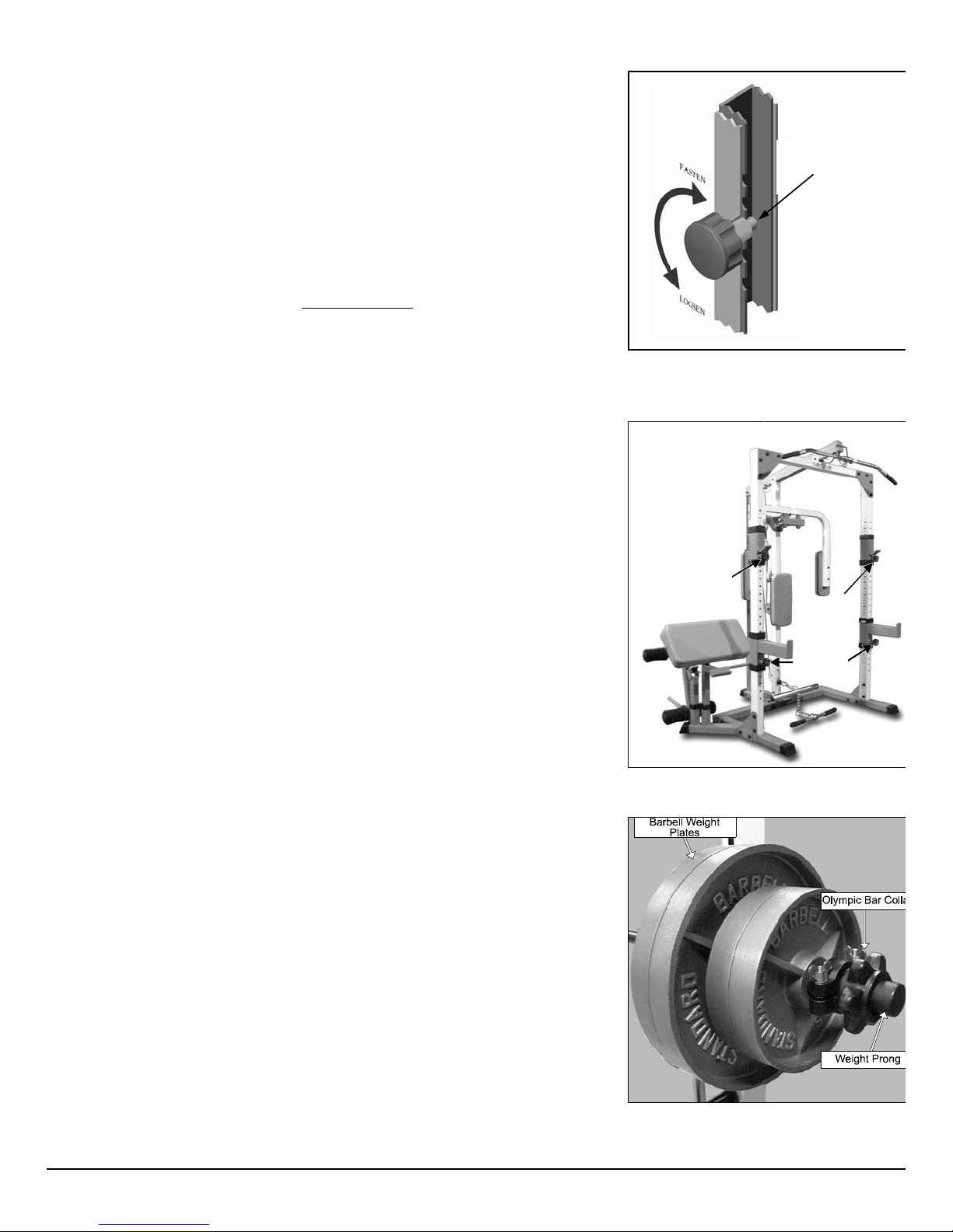
Loosely Fasten provides a instruction to loosely
fasten (ex: hand tighten) a hardware assembly
only. This instruction is intended for the alignment
LOOSELY FASTEN
FULLY FASTEN
of hardware components during the assembly
process.
Fully Fasten provides a instruction to fully fasten
(ex: completely tighten) a hardware assembly.
Note: Due to continuing product improvements, specifications and designs are subject to change
without notice.
Page 3
afety First
Safety Precautions
w
egardless of how enthusiastic you may be about getting on your equipment and
xercising, take the time to ensure that your safety is not jeopardized. A moment’s
ack of attention can result in an accident, as can failure to observe certain simple
afety precautions.
. Read, study and understand the Owner’s Manual and all the warning labels on
this product. Furthermore, it is recommended to familiarize yourself and others
with the proper operation and workout recommendations for this Tuff Stuff product prior to use. Some of this information can be obtained in this Owner’s Manual, as-well-as from your local Tuff Stuff Retailer.
. For proper technique and general conditioning or weight training program, we
recommend the book by Bill Pearl, Getting Stronger (ISBN 0-936070-04-8) the
most complete book on weight training! Over 350 exercises for free weights and
universal machines, easy-to-use training programs and up-to-date information on
muscles and nutrition.
. It is imperative that you retain this Owner’s Manual and be sure all warning labels
are legible and intact. Replacement of Owner’s Manual and labels are available
from your local Tuff Stuff Retailer.
. Consult with your physician before beginning any exercise program.
. Use proper discretion when children are present.
Turn/ Pull Pin w/Knob
Fully Engaged
Fig. A Caution: Check that all Turn/ Pull Pins
Knob (#72) are fully engaged into the selectorized
holes.
. Keep hands, limbs, loose clothing and long hair well out of the way of moving
parts.
. Do not attempt to lift more weight than you can control safely.
. Inspect the Half Cage Ensemble for any sign of wear on parts, hardware becom-
ing loose or cracks on welds. If a Problem is found do not use or allow the ma-
chine to be used until defective part is repaired or replaced.
. Frayed or worn cables can be dangerous and may cause injury. Periodically
check cables for any indication of wear.
0.Pay special attention to the Turn Pull Pins w/Knob (#72) located on the Bar
Holders (#4), and the Bar Safeties (#5). Be sure they are fully engaged into
the selectorized holes of the Selectorized Uprights (#6). Refer to Fig. A
and B for further illustration.
1.Use collars to prevent the Weight Plates from falling off the Weight Carriage
(#37) or lifting Bars. Refer to Fig. C for further illustration.
Turn Pull
Pin w/Knob
Turn Pull
Pin w/Knob
Turn Pull
Pin w/Knob
Fig. B Illustration above depicts the location of
the Turn Pull Pins w/Knob (#72) on this unit.
Fig. C Caution: Use collars to prevent the
weight plates from falling off the Weight Carriage
(#37) or Lifting Bars.
Page 4
e
d
a
l
l
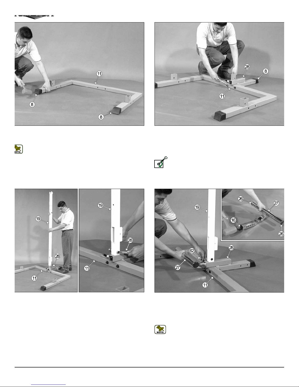
g. 1 On a flat surface, lay the Base Frame (#11) down and, using a
e
h
l
i
bber mallet, insert two Plastic End Caps w/Groove 2 x 3 (#8) onto the
be-ends.
Note: When positioning the Base Frame (#11) consider the complete area surface of the TDH-345WS. Use the overhead view on the
cover page for designing your layout before assembling.
Fig. 2 Locate the Bottom Assembly Holder (#28) and, using a rubb
mallet insert one Plastic End Cap w/Groove 2 x 3 (#8) onto the tube-en
Next, attach the Bottom Assembly Holder (#28) to the Base Frame (#11
in the position as shown above, and secure it into place using two Hex He
Cap Screws 1/2-13 X 4 1/4 (#12), four Flat Washers SAE 1/2” (#10), an
two Nylon Insert Lock Nuts 1/2-13 (#9).
Loosely Fasten: Do not completely fasten this hardware assemb
at this time, as it will be completely fastened later in the assemb
LOOSELY FASTEN
process.
g. 3 Insert the Center Upright (#19) onto the receptacle located on
e Bottom Assembly Holder (#28), in the position as shown above, and
cure into place using one Hex Head Cap Screw 3/8-16 X 2 1/2 (#29), two
at Washers SAE 3/8” (#45), and one Nylon Insert Jam Lock Nut 3/8-16
46).
Fig. 4 Locate the Adjustable Foot Support (#27) and, using a rubb
mallet, insert two Plastic Insert Caps 2” Rd. (#26), and one Plastic Inse
Cap 1 3/4 “ Sq. (#16) into the tube-ends, as shown above.
Insert the Adjustable Foot Support (#27), with the selector holes facing t
Push Pull Pin 1/2” (#62), into the receptacle of the Bottom Assemb
Holder (#28).
Note: Be sure to pull the Push Pull Pin 1/2” (#62) as you perform th
assembly.
Page 5
c
y
p
w
h
l
S
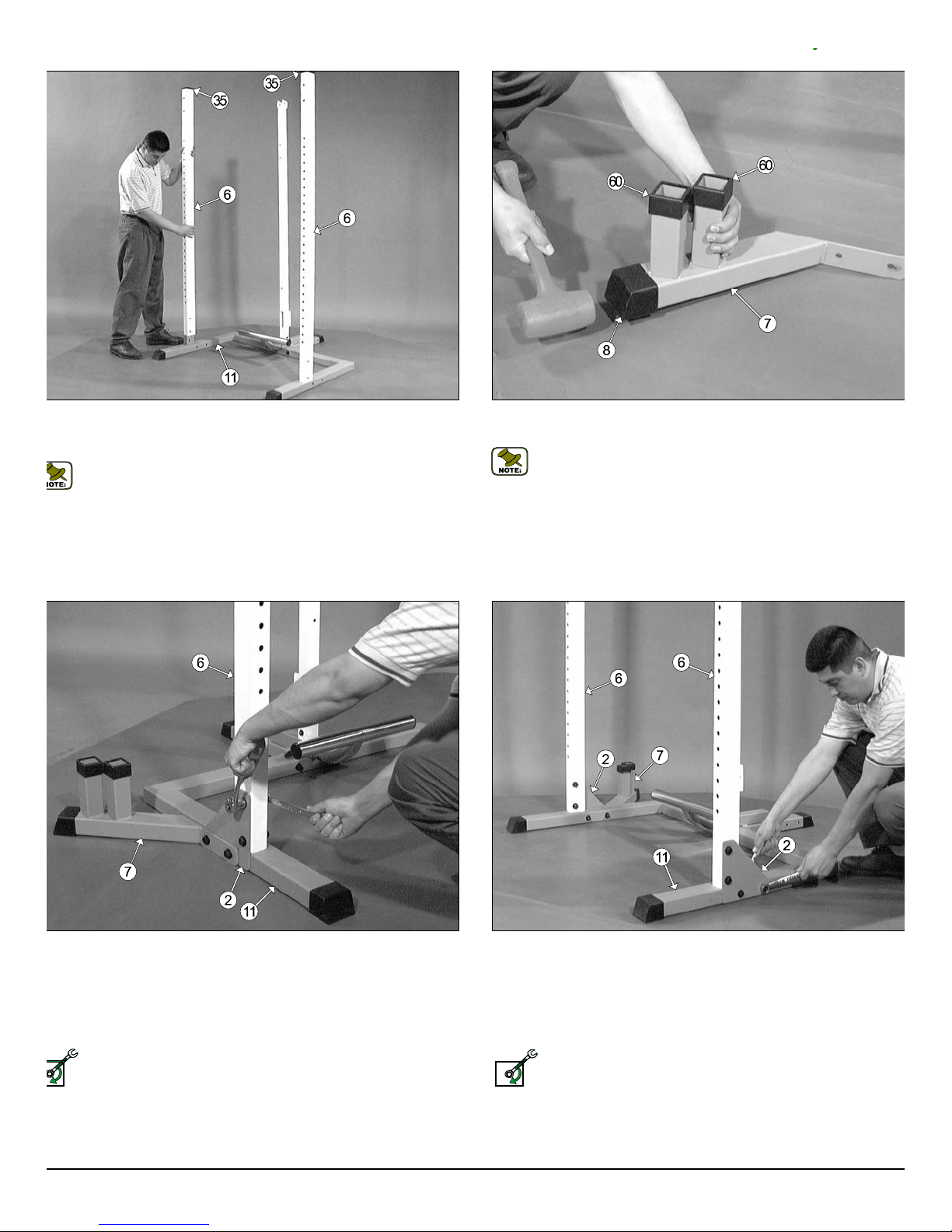
g. 5 Insert the two Selectorized Uprights (#6) onto the receptacles
cated on the Base Frame (#11), in the position as shown above with the
le pattern facing away from the unit.
Note: The two Plastic Insert Caps 2 X 3 (#35) located on top of the
Selectorized Uprights (#6) have been assembled by the factory.
Fig. 6 Using a rubber mallet, insert one Plastic End Cap w/Groove 2 X
(#8) onto the tube-end of the Accessory Rack (#7).
Note: The two Plastic Tube Guides 2” Sq. (#60) located on the A
cessory Rack (#7) have been assembled by the factory.
g. 7 Attach the Accessory Rack (#7) and a Triangular Corner Plate
2) to the Base Frame (#11), in the position as shown above, using two
ex Head Cap Screws 1/2-13 X 4 1/2 (#14), four Flat Washers SAE
2” (#10), and two Nylon Insert Lock Nuts 1/2-13 (#9). Next, affix the Trian-
lar Corner Plate (#2) to the Selectorized Upright (#6) using two Hex
ead Cap Screws 1/2-13 X 3 (#13), four Flat Washers SAE 1/2” (#10), and
o Nylon Insert Lock Nuts 1/2-13 (#9).
Loosely Fasten: Do not completely fasten this hardware assembly
at this time, as it will be completely fastened later in the assembly
process.
ELY FASTEN
Fig. 8 Attach a Triangular Corner Plate (#2) to the Selectorized U
right (#6), in the position as shown above, using two Hex Head Cap Scre
1/2-13 X 3 (#13), four Flat Washers SAE 1/2” (#10), and two Nylon Inse
Lock Nuts 1/2-13 (#9). Next, affix the Triangular Corner Plate (#2) to t
Base Frame (#11), using two Hex Head Cap Screws 1/2-13 X 4 1/4 (#12
four Flat Washers SAE 1/2” (#10), and two Nylon Insert Lock Nuts 1/2-1
(#9).
Loosely Fasten: Do not completely fasten this hardware assemb
at this time, as it will be completely fastened later in the assemb
LOOSELY FASTEN
process.
Page 6
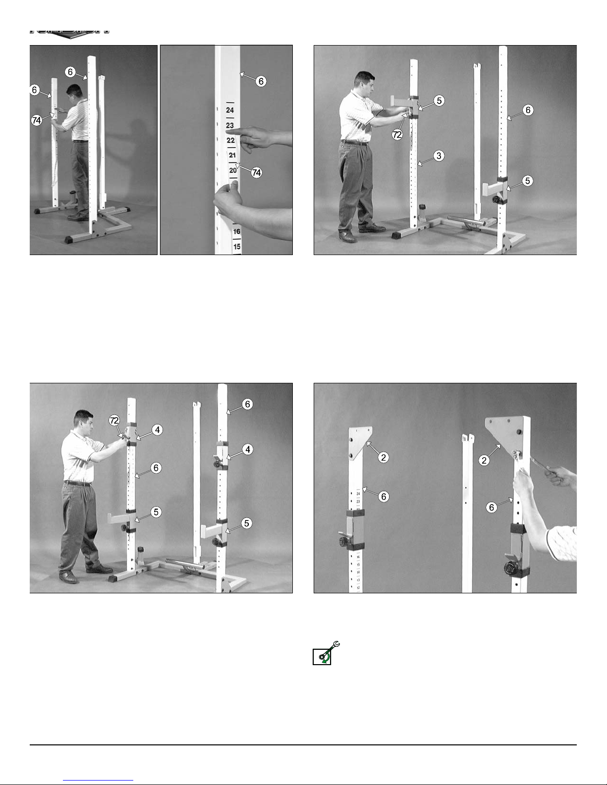
g. 9 Next, attach the Decal Numbers 1-24 (#74) on the inside of the
e
u
w
e
l
l
lectorized Uprights (#6). Center the number 24 with the top adjustment
le of the Selectorized Uprights (#6). A great way to make sure you don’t
p any air bubbles under the decal is by using the wedge method. Press
e side of your index finger against the decal and as you slide your finger
wn, with the other hand, slowly remove the rest of the backing off the del.
Fig. 10 Slide one Bar Safety (#5), in the position as shown above, ov
each one of the Selectorized Uprights (#6). Be sure to pull the Turn P
Pin w/Knob (#72) as you perform this assembly.
g. 11 Slide one Bar Holder (#4), in the position as shown above, over
ch one of the Selectorized Uprights (#6). Be sure to pull the Turn Pull
n w/Knob (#72) as you perform this assembly.
Fig. 12 Attach two Triangular Corner Plates (#2) to the front of the t
Selectorized Uprights (#6), in the position as shown above, using four H
Head Cap Screws 1/2-13 X 4 1/4 (#12), eight Flat Washers SAE 1/2” (#10
and four Nylon Insert Lock Nuts 1/2-13 (#9).
Loosely Fasten: Do not completely fasten this hardware assemb
at this time, as it will be completely fastened later in the assemb
LOOSELY FASTEN
process.
Page 7

s
t
r
h
c
y
s
.
S
Caution: It is recommended to use another person in assisting with
this assembly.
Fig. 14 Mount the Chrome Post Receptacle (#43) onto the Bottom A
sembly Holder (#28), in the position as shown above, and secure it in
place using two Hex Head Cap Screws 3/8-16 x 4 (#32), four Flat Washe
g. 13 Affix the Top Stabilizer (#3) to the two Triangular Corner Plates
2), in the position as shown above, and secure it into place using four Hex
ead Cap Screws 1/2-13 X 4 1/4 (#12), eight Flat Washers SAE 1/2” (#10),
d four Nylon Insert Lock Nuts 1/2-13 (#9).
SAE 3/8” (#45), and two Nylon Insert Jam Lock Nuts 3/8-16 (#46).
Note: The two Pyramid Rubber Bumpers (#34) located on t
Chrome Post Receptacle (#43) have been assembled by the fa
tory.
Loosely Fasten: Do not completely fasten this hardware assembly
at this time, as it will be completely fastened later in the assembly
process.
ELY FASTEN
g. 15 Next, insert the Chrome Post (#31) into the Chrome Post Re-
ptacle (#43), in the position as shown above, and secure it into place
ing one Hex Head Cap Screw 3/8-16 X 2 3/4 (#33), two Flat Washers
E 3/8” (#45), and one Nylon Insert Jam Lock Nut 3/8-16 (#46). Refer to
e Exploded View Diagram on page 18 for further illustration on this assem-
y.
Fig. 16 Carefully slide the Weight Carriage (#37) onto the Chrome Po
(#31), with the weight prongs toward the inside of the unit, as shown above
Page 8

a
x
1
l
a
Caution: It is recommended to use another person in assisting with
h
n
u
this assembly.
ig. 17 Insert the receptacle of the Top Pulley Housing (#1) onto the
hrome Post (#31), then mount the Top Pulley Housing (#1) into the
rackets of the Center Upright (#19), and the Top Stabilizer (#3).
ext, secure the Top Pulley Housing (#1) to the Top Stabilizer (#3), and
e Chrome Post (#31) using two Hex Head Cap Screws 3/8-16 X 2 3/4
33), four Flat Washers SAE 3/8” (#45), and two Nylon Insert Jam Lock
uts 3/8-16 (#46).
Note: Do not secure the Top Pulley Housing (#1) to the Center Up-
right (#19) at this time.
Fig. 18 Locate the Upper Swivel Bracket (#25) and thread a Regul
Hex Nut 1/2-13 (#73) and insert one Flat Washer SAE 1/2” (#10). Ne
insert the Upper Swivel Bracket (#25) into the Top Pulley Housing (#
receptacle and secure it into place using one Flat Washer SAE 1/2” (#10
and one Nylon Insert Jam Lock Nut 1/2-13 (#52).
Loosely Fasten: Do not completely fasten this hardware assemb
at this time to allow cable adjustment once the cable routing h
LOOSELY FASTEN
been completed.
g. 19 Attach the Lat Bar Holder (#55) to the Top Pulley Housing (#1)
d secure it into place using one Hex Head Cap Screw 3/8-16 X 2 1/2
29), two Flat Washers SAE 3/8” (#45), and one Nylon Insert Jam Lock Nut
8-16 (#46).
Fig. 20 Locate the Pec Dec Housing (#15) and, using a rubber malle
insert two Plastic Insert Caps 2” SQ. (#16) into each of the tube-ends of t
Pec Dec Housing (#15).
Next, affix the Pec Dec Housing (#15) to the Center Upright (#19) a
secure it into place using two Hex Head Cap Screws 3/8-16 X 3 (#67), fo
Flat Washers SAE 3/8” (#45), and two Nylon Insert Lock Nuts 3/8-16 (#48
Refer to the Exploded View Diagram on page 18 for further illustration of th
assembly.
Page 9

n
o
w
o
t
/
L
e
y
g. 21 Locate the Pec Dec Arm Lt. (#38) and the Pec Dec Arm Rt.
39) and, using a rubber mallet, insert two Plastic Insert Caps 1 3/4” SQ.
71) into each of the tube-ends, as shown above.
ext, insert the axles of the Pec Dec Arm Lt. (#38) and the Pec Dec Arm
. (#39) into the Pec Dec Housing (#15), as shown above.
Note: It is recommended to grease the axles of the Pec Dec Arms
(#38, #39) with multi-purpose grease prior to assembling them to the
Pec Dec Housing (#15).
Fig. 22 Secure both Pec Dec Arms (#38, #39) to the Pec Dec Housin
(#15) using two Exterior Retainer Rings (#42). Use a External retaining-ri
pliers for this job. If this tool is not available, carefully work each Exteri
Retainer Ring (#42) into the groove, then push-up alternately with a scre
driver working the Exterior Retainer Ring (#42) into the groove.
Note: Be careful not to distort the Exterior Retainer Rings (#42)
bend them.
g. 23 Attach the Back Pad Pulley Bracket (#23) to the Center Upright
19) and secure it into place using one Hex Head Cap Screw 3/8-16 X 2
4 (# 33), two Flat Washers SAE 3/8” (#45), and one Nylon Insert Jam Lock
ut 3/8-16 (#46). Refer to the Exploded View Diagram on page 18 for furer illustration of this assembly.
Note: One Hex Head Cap Screw 1/4-20 X 1 1/2 (#68), and one Nylon
Insert Lock Nut 1/4-20 (#69) have been assemble to the Back Pad
Pulley Bracket (#23) by the factory. This assembly works as a cable
retainer.
ext, attach the Back Pad (#18) to the Back Pad Pulley Bracket (#23), in
e position as show above, using two Hex Head Cap Screws 3/8-16 X 1 1/4
83), and two Flat Washers SAE 3/8” (#45).
Fig. 24 Locate the two Pec Dec Arm Pads (#17) and attach one to th
Pec Dec Arm Rt. (#39) using two Hex Head Cap Screws 3/8-16 X 2 3
(#33), and two Flat Washers SAE 3/8” (#9), as shown above.
Next, attach the other Pec Dec Arm Pad (#17) to the Pec Dec Ar m
(#38) using one Hex Head Cap Screws 3/8-16 X 3 1/4 (#82), one Rubb
Bumper 3/8 X 1 1/2 (#65), one Hex Head Cap Screw 3/8-16 X 2 3/4 (#33
and one Flat Washers SAE 3/8” (#45), as shown above.
Page 10

0
t
h
e
e
0
c
e
e
e
m
a
t
y
g. 25 Begin routing the Pec Dec Cable (#40) by attaching it to the Pec
ec Arm Rt. (#38) using one Hex Head Cap Screw 3/8-16 X 1 (#47), two
at Washers SAE 3/8” (#45), and one Nylon Insert Jam Lock Nut 3/8-16
46). Repeat the same procedure to attach the Pec Dec Cable (#40) to
e Pec Dec Arm Lt. (#38).
Note: Refer to the Cable Mapping Diagram on page 18 for further
clarification of the Pec Dec Cable (#40) routing.
Fig. 26 Next, insert the Pec Dec Cable (#40) through the pulley brack
on the Pec Dec Housing (#15) and install one Nylon Pulley 4 1/2” Rd. (#2
Labeled J). Secure it into place using one Hex Head Cap Screw 3/8-16 X
3/4 (#30), two Flat Washers SAE 3/8” (#45), and one Nylon Insert Jam Lo
Nut 3/8-16 (#46). Repeat the same procedure to route and secure the P
Dec Cable (#40) through the pulley bracket on the opposite side of the P
Dec Housing (#15).
Note: The black boxed letters pointing to the pulleys are us
throughout this manual as reference to the Cable Mapping Diagra
on page 18 These black boxed letters will be primarily used for loc
ing certain pulleys during the cable routing process beginning wi
Fig. 26.
g. 27 Next, insert one Nylon Pulley 4 1/2” Rd. (#20-Labeled H) and the
c Dec Cable (#40) into the Pec Dec Floating Pulley Bracket (#22) and
cure them into place using one Hex Head Cap Screw 3/8-16 X 1 1/2
70), two Steel Bumper Washers 3/8” (#58), and one Nylon Insert Jam
ck Nut 3/8-16 (#46).
ext, snap one Plastic Bumper End Cap (#57) over each Steel Bumper
asher 3/8” (#58). Place the Plastic Bumper End Cap (#57) over one edge
the Steel Bumper Washer 3/8” (#58) and use gentle pressure with the
umb to snap the Plastic Bumper End Cap (#57) into place.
Note: Refer to the Exploded View Diagram and Cable Mapping Diagram on page 18 for further clarification of this assembly.
Fig. 28 Insert the Lat Cable (#53) and a Nylon Pulley 4 1/2” Rd. (#2
Labeled A) into the pulley bracket located on the Top Pulley Housing (#1
as shown, then secure the Nylon Pulley 4 1/2” Rd. (#20-Labeled A) in
place using one Hex Head Cap Screw 3/8-16 X 2 1/2 (#29), two Flat Was
ers SAE 3/8” (#45), and one Nylon Insert Jam Lock Nut 3/8-16 (#46).
Note: Refer to the Cable Mapping Diagram on page 18 for furth
clarification of the Lat Cable (#53) routing.
Page 11

o
a
)
e
s
8
r
t
y
ig. 29 Route the end of the Lat Cable (#53) through the Top Pulley
ousing (#1) tube. Next, pull gently the Lat Cable (#53) down through the
ot on the bottom side of the Top Pulley Housing (#1).
Caution: Do not pull the Lat Cable (#53) all the way through the Top
Pulley Housing (#1) until you have installed the Nylon Pulley 4 1/2”
Rd. (#20-Labeled B), as this will prevent any damage to the Cable.
See Fig. 30.
Note: Refer to the Cable Mapping Diagram on page 18 for further
detailed illustration of the Lat Cable (#53) routing.
Fig. 30 Insert one Nylon Pulley 4 1/2” Rd. (#20-Labeled B) into the slot
the Top Pulley Housing (#1), in the position as shown above, and secure
into place using one Hex Head Cap Screw 3/8-16 X 2 1/2 (#29), two Fl
Washers SAE 3/8” (#45), and one Nylon Insert Jam Lock Nut 3/8-16 (#46
Be sure the Lat Cable (#53) is routed properly into the pulley’s groove.
Note: Refer to the Cable Mapping Diagram on page 18 for furth
detailed illustration of the Lat Cable (#53) routing.
ig. 31 Secure the Top Pulley Housing (#1) to the Center Upright (#19)
ing one Hex Head Cap Screw 3/8-16 X 2 3/4 (#33), two Flat Washers
AE 3/8” (#45), and one Nylon Insert Jam Lock Nut 3/8-16 (#46).
Caution: To prevent damage to the Lat Cable (#53), it is important to
make sure that the Lat Cable (#53) is routed over the top, and not
under the Hex Head Cap Screw 3/8-16 X 2 3/4 (#33).
Fig. 32 Assemble the two Double Pulley Plates (#21) using two Nylo
Pulleys 4 1/2” Rd. (#20-Labeled C and F), two Hex Head Cap Screws 3/
16 X 1 3/4 (#30), four Flat Washers SAE 3/8” (#45), and two Nylon Inse
Jam Lock Nuts 3/8-16 (#46).
Note: The four holes on the Double Pulley Plates (#21) are used
adjust the cable tension once the cable routing has been completed.
Page 12

n
a
m
ig. 33 Route the Lat Cable (#53) through the Double Pulley Plates
s
y
e
21) and under the Nylon Pulley 4 1/2” Rd. (#20-Labeled C). Next, insert
e Cable and one Nylon Pulley 4 1/2” Rd. (#25-Labeled D) into the Upper
wivel Bracket (#25), in the position as shown above. Secure the Pulley
to place using one Hex Head Cap Screw 3/8-16 X 1 3/4 (#30), two Flat
ashers SAE 3/8” (#45), and one Nylon Insert Jam Lock Nut 3/8-16 (#46).
Fig. 34 Next, route the Lat Cable (#53) down and secure the looped e
to the bracket on the Weight Carriage (#37) using one Hex Head C
Screw 3/8-16 X 1 (#47), and one Nylon Insert Jam Lock Nut 3/8-16 (#46).
Note: Refer to Fig. B on page 18 for further illustration of this asse
bly.
Note: Refer to the Cable Mapping Diagram on page 18 for further
detailed illustration of the Lat Cable (#53) routing.
ig. 35 Route the Low Row Cable (#54) through the Center Upright’s
19) pulley bracket, then insert one Nylon Pulley 4 1/2” Rd. (#20-Labeled
) into the Center Upright’s (#19) pulley bracket and secure it into place
ing one Hex Head Cap Screw 3/8-16 X 1 3/4 (#30), two Flat Washers
AE 3/8” (#45), and one Nylon Insert Jam Lock Nut 3/8-16 (#46). Be sure
e Low Row Cable (#54) is routed properly into the pulley’s groove.
Note: Refer to the Cable Mapping Diagram on page 18 for further
detailed illustration of the Low Row Cable (#54) routing.
Fig. 36 Continue routing the Low Row Cable (#54) up and over the N
lon Pulley 4 1/2” Rd. (#20-Labeled F) and through the Double Pulley Plate
(#21), as shown above.
Note: Refer to the Cable Mapping Diagram on page 18 for furth
detailed illustration of the Low Row Cable (#54) routing.
Page 13

o
e
n
o
m
y
ig. 37 Next, insert the Low Row Cable (#54) and the Nylon Pulley 3 1/2”
d. (#24-Labeled G) into the Back Pad Pulley Bracket (#23) and secure
em into place using one Hex Head Cap Screw 3/8-16 X 1 3/4 (#30), two
lat Washers SAE 3/8” (#45), and one Nylon Insert Jam Lock Nut 3/8-16
46). Be sure the Low Row Cable (#54) is routed properly into the pulley’s
roove.
Note: Refer to the Cable Mapping Diagram on page 18 for further
detailed illustration of the Low Row Cable (#54) routing.
Fig. 38 Affix the Low Row Cable (#54) to the Pec Dec Floating Pulle
Bracket (#22) using one Hex Head Cap Screw 3/8-16 X 1 (#47), and on
Nylon Insert Jam Lock Nut 3/8-16 (#46). Refer to Fig. C on page 18 f
further illustration of this assembly.
Note: Refer to the Cable Mapping Diagram on page 18 for furth
detailed illustration of the Low Row Cable (#54) routing.
g. 39 Insert two Hard Grips 1 X 6 (#56) onto each of the tube-ends of
e Low Row Bar (#51).
Note: Use Windex or household glass cleaner for easy insertion of
the Hard Grips 1 X 6 (#56).
ext, connect the Low Row Bar (#51) to the Low Row Cable (#54) using
e Coil Chain 3/16” X 21 (#59), and two Snap Links (#49), as shown above.
Fig. 40 Multiple starting exercise positions can be achieved by connecti
the Low Row Bar to the Coil Chain Links with out loosing traveling range
the Weight Carriage.
Note: Optional Cable Attachments can be utilized within the sa
manner, for example: D Handle, Ankle Strap, etc.
Page 14

u
m
g. 41 Insert two Hard Grips 1 X 6 (#56) onto each of the tube-ends of
p
P
e
t
a
e Lat Bar (#50).
Note: Use Windex or household glass cleaner for easy insertion of
the Hard Grips 1 X 6 (#56).
ext, mount the Lat Bar (#50) onto the Lat Bar Holder (#55) and affix it to
e Lat Cable (#53), in the position as shown above, using one Snap Link
22), one Shoulder Bolt 3/8 X 3/4 (#63), and one Nylon Insert Lock Nut
16-18 (#66). Use the supplied Hex Key 3/16” (#81) and a 1/2” combina-
n wrench to fasten this assembly properly. Refer to Fig. A on page 18 for
rther illustration of this assembly.
Fig. 42 Multiple starting exercise positions can be achieved by using th
Coil Chain as an extension to connect the Lat Bar to the Lat Cable with o
loosing traveling range on the Weight Carriage.
Note: Optional Cable Attachments can be utilized within the sa
manner, for example: Tricep Bar, D Handle, etc.
ig. 43 Locate the Leg Hold-Down Tube (#76) and, using a rubber mal-
t, insert two Plastic Insert Caps 1 3/4” Sq. (#71) into each of the tube-
nds.
ext, insert the Foot Roll Tube (#77) into the receptacle of the Leg Hold-
own Tube (#76), then insert two Foam Foot Rolls 7 X 4 X 1 (#78) over
ch of the tube-ends of the Foot Roll Tube (#77), as shown above.
Note: Use Windex or household glass cleaner for easy insertion of
the Foam Foot Rolls 7 X 4 X 1 (#78).
Fig. 44 Using a rubber mallet, insert two Foot Roll Plastic End Ca
1” (#79) into each of the tube-ends of the Foot Roll Tube (#77).
Next, insert the Leg Hold Down Assembly into the receptacle of the *TM
75 (Multi-Angular Bench). Use the L-Locking Pin (#80) to Adjust the L
Hold Down Assembly to the desired height.
*Assembly Instructions for the TMP-75 (Multi-Angular Bench) come in i
own box.
Page 15

r
s
y
TLC-185
TPA-16
g. 45 Once assembled or when not in use, the TLC-185 Leg Extension/
url and the TPA-16 Preacher Curl can be stored on the Accessory Rack,
illustrated above.
Fig. 46 This concludes the assembly of the TDH-345.
Do a careful inspection of each and every assembly and make sure they a
done properly to ensure a safe and smooth operation.
Fully Fasten: Proceed to align and fully fasten all the previous a
semblies that were left loosely fastened.
FULLY FASTEN
Page 16

CABLE ADJUSTMENT DIAGRAM
1. Loosen the bottom Finished Hex Nut 12-13
2. Adjust the top Nylon Insert Lock Nut 1/2-13
3. Re-tighten the bottom Finished Hex Nut 12-13
1. Remove the hardware from the Nylon Pulley 4
2. By interchanging the Nylon Pulley 4 1/2” Rd.
3. Re-tighten the hardware for the Nylon Pulley 4
Minor Cable Adjustment:
Use the Upper Swivel Pulley Bracket (#25)
(#73).
(#52) to give the cable proper tension.
(#73) to complete the cable adjustment.
Major Cable Adjustment:
Use the Double Pulley Plates (#21)
1/2” Rd. (#20-Labeled F) located at one of the
four holes on the Double Pulley Plates (#21).
(#20-Labeled F) in the Double Pulley Plates
(#21) to the next adjustment hole it will make
one inch cable adjustment.
1/2 Rd. (#20-Labeled F) to complete the cable
adjustment.
Page 17

o
e
a
e
2
s
d
7
d
d
h
Maintenance
y
M aintenance Information
1. Lubrication of all moving parts is essential to the longevity
and optimal performance of your Half Cage Ensemble.
Initial lubrication of some parts of your gym have been
done at the factory, but the Chrome Post (#31) must be
lubricated regularly. We recommend a clear aerosol, silicone or teflon spray.
Note: Do not use oil based lubricants as they will attract
dust, dirt and grime, and will eventually gum up and erode
bushings and sealed bearings.
6. Chrome plated surfaces should be cleaned regularly t
prolong the life and luster of the finish. Wipe machin
down with a damp cloth and dry thoroughly each day or a
needed.
7. When checking the bolts and nuts, be sure they are
fully fastened. If there is a bolt or nut that continuousl
loosens obtain a replacement thru your local Tuff Stuff r
tailer or call our Customer Service Department.
2. All pulleys and bushings should be checked regularly for
signs of wear.
3. Check and adjust tension on cables periodically as it will
maintain proper anatomical function.
4. Periodically check all parts for signs of wear or damage. If
there is a problem or replacement of a part is necessary,
STOP USING THE EQUIPMENT and immediately contact
your local Tuff Stuff retailer or call our Customer Service
Department. Replace parts using only genuine Tuff Stuff
parts.
5. Check welds to be free of cracks.
Turn/ Pull Pin w/Knob Fully
Engaged
8. Pay special attention to the Turn/ Pull Pins w/Knob (#7
located on the Bar Holders (#4) and the Bar Safetie
(#5). Be sure they are fully engaged into the selectorize
holes of the Selectorized Uprights (#6). Refer to Fig. 4
for further illustration.
9. Check that the Push Pull Pin 1/2” (#62) Hex Nut locate
on the Bottom Assembly Holder (#28) is fully fastene
(See Fig. 48) in addition, be sure the spring in the Pus
Pull Pin 1/2” (#62) is operating freely.
10.Failure to perform routine maintenance could result i
personal injury and/or equipment damage.
ig. 47 Caution: Check that all Turn/ Pull Pins w/Knob (#72)
are fully engaged into the selectorized holes.
Push Pull
Pin Hex Nut
Fig. 48 Caution: Be sure the Push Pull Pin Hex Nut is full
fastened. Fasten if necessary.
Push Pull
Pin Hex Nut
Page 18

COLOR CHART
COLOR CHART
GRAY= SUB-ASSEMBLY PARTS
GRAY= SUB-ASSEMBLY PARTS
BLACK= HARDWARE
BLACK= HARDWARE
Item No. Description Part No. Qty Item No. Description Part No. Qty
1 TOP PULLEY HOUSING UP0722 143CHROME POST RECEPTACLE UP0730 1
2 TRIANGULAR CORNER PLATE UP0101 444BRONZE BUSHING 1 X 1 1/4 X 3/4 BNH0527 4
3 TOP STABILIZER UP0723 145FLAT WASHER SAE 3/8 BNH0239 56
4 BAR HOLDER W/SOLID HOOK UP0704 246NYLON INSERT JAM LOCK NUT 3/8-16 BNH0365 26
5 BAR SAFETY SPOTTER W/SOLID HOOK UP0702 247HEX HEAD CAP SCREW 3/8-16 X 1 BNH0275 4
6 SELECTORIZED UPRIGHT UP0724 248NYLON INSERT LOCK NUT 3/8-16 BNH0214 2
7 ACCESSORY RACK UP0725 149SNAP LINK BNH0065 3
8 PLASTIC END CAP 2 X 3 W/GROOVE BNH0049 4 50 LAT BAR 48" BNH0295 1
9 NYLON INSERT LOCK NUT 1/2 -13 BNH0212 18 51 LOW ROW BAR 20" BNH0294 1
10 FLAT WASHER SAE 1/2 BNH0238 38 52 NYLON INSERT JAM LOCK NUT 1/2-13 BNH0366 1
11 BASE FRAME UP0726 153LAT CABLE UP0618 1
12 HEX HEAD CAP SCREW 1/2-13 X 4 1/4 BNH0291 12 54 LOW ROW CABLE UP0514 1
13 HEX HEAD CAP SCREW 1/2-13 X 3 BNH0264 4 55 LAT BAR HOLDER 2 X 3 UP0096 1
14 HEX HEAD CAP SCREW 1/2-13 X 4 1/2 BNH0265 2 56 HARD GRIP 1 X 6 BNH0296 4
15 PEC DEC HOUSING UP0547 157PLASTIC BUMPER END CAP BNH0412 2
16 PLASTIC INSERT CAP 2" SQ BNH0012 3 58 STEEL BUMPER WASHER 3/8" BNH0498 2
17 PEC DEC ARM PAD UP0548 259COIL CHAIN 3/16 X 21 BNH0017 1
18 BACK PAD UP0112 160PLASTIC TUBE GUIDE 2" SQ BNH0058 2
19 CENTER UPRIGHT UP0727 161PLASTIC TUBE GUIDE 2 1/2 X 3 1/2 BNH0057 8
20 NYLON PULLEY 4 1/2 RD BNH0556 9 62 PUSH-PULL PIN 1/2" BNH0515 1
21 DOUBLE PULLEY PLATE UP0092 263SHOULDER BOLT 3/8 X 3/4 BNH0718 1
22 PEC DEC FLOATING PULLEY BRACKET UP0110 164STRAP BRACKET #20 BNH0562 1
23 BACK PAD PULLEY BRACKET UP0111 165RUBBER BUMPER 3/8 X 1 1/2 BNH0514 3
24 NYLON PULLEY 3 1/2" RD BNH0553 1 66 NYLON INSERT LOCK NUT 5/16-18 BNH0215 1
25 UPPER SWIVEL BRACKET UP0149 167HEX HEAD CAP SCREW 3/8-16 X 3 BNH0264 2
26 PLASTIC INSERT CAP 2" RD BNH0004 2 68 HEX HEAD CAP SCREW 1/4 -20 X 1 1/2 BNH0272 1
27 ADJUSTABLE FOOT SUPPORT UP0109 169NYLON INSERT LOCK NUT 1/4 -20 BNH0213 1
28 BOTTOM ASSEMBLY HOLDER UP0728 170HEX HEAD CAP SCREW 3/8-16 X 1 1/2 BNH0303 1
29 HEX HEAD CAP SCREW 3/8-16 X 2 1/2 BNH0276 4 71 PLASTIC INSERT CAP 1 3/4 SQ. BNH0053 2
30 HEX HEAD CAP SCREW 3/8-16 X 1 3/4 BNH0274 7 72 TURN PULL PIN W/KNOB BNH0929 4
31 CHROME POST UP0729 173REGULAR HEX NUT 1/2-13 BNH0201 1
32 HEX HEAD CAP SCREW 3/8-16 X 4 BNH0285 2 74 DECAL NUMBERS 1-24 BNH0147 2
33 HEX HEAD CAP SCREW 3/8-16 X 2 3/4 BNH0278 8 75 PLASTIC INSERT CAP 1 1/4 SQ. BNH0010 1
34 PYRAMID RUBBER BUMPER BNH0013 2 76 LEG HOLD-DOWN TUBE UP0266 1
35 PLASTIC INSERT CAP 2 X 3 BNH0052 2 77 FOOT ROLL TUBE UP0053 1
36 NYLON STEM BUTTON 3/16 BNH0533 12 78 FOAM FOOT ROLL 7 X 4 X 1 BNH0043 2
37 WEIGHT CARRIAGE 21" UP0118 179FOOT ROLL PLASTIC END CAP 1" BNH0397 2
38 PEC DEC ARM LT UP0545 180L-LOCKING PIN BNH0045 1
39 PEC DEC ARM RT UP0546 181HEX KEY 3/16" BNH0371 1
40 PEC DEC CABLE UP0541 182HEX HEAD CAP SCREW 3/8-16 X 3 1/4 BNH0312 1
41 HEX HEAD CAP SCREW 3/8-16 X 3/4 BNH0283 2 83 HEX HEAD CAP SCREW 3/8-16 X 1 1/4 BNH0273 2
42 EXTERIOR RETAINER RING BHN0419 2
TDH-345
Parts List
Page 19

L
EXPLODED VIEW DIAGRAM
BUTTONS
PRE-INSTA
ON CARRIA
PEC DEC TOP VIEW
SIMPLIFIED
VIEWS
(PEC DEC)
PEC DEC REAR VIEW
CABLE MAPPING DIAGRAM
SEE
FIG. A
SEE
FIG. C
SEE
FIG. B
FIG. A
FIG. B
FIG. C
VARIOUS PARTS
CUT OUR FOR CLARITY
Page 20

DO NOT DISCARD THIS MANUAL
HOME LIFETIME WARRANTY
TuffStuff products are warranted to the retail purchaser to be free from defects in materials and workmanship.
TuffStuff exclusive Home Lifetime Warranty coverage extends for the life of the product while owned by the
original retail purchaser, and used only in a home or residential setting unless otherwise noted in the owner’s
manual.
This warranty does not cover:
1. TuffStuff products sold for and used in a commercial or institutional setting.
2. Any damage, failure or loss caused by accident, misuse, neglect, abuse, improper assembly, improper
maintenance, or failure to follow instructions or warnings in the owner’s manual and warning labels
posted on the machine.
3. Use of products in a manner for which they were not designed.
4. Original product that is altered, or the use of replacement parts and components of another manufacturer other than TuffStuff.
Limitations:
The foregoing shall constitute the sole remedy of the purchaser and the sole liability of TuffStuff with regard to
warranty, whether express or implied by operation of law or otherwise, including but not limited to any implied
warranties of merchantability or fitness. TuffStuff shall in no event be liable for incidental or consequential
losses, damages or expenses in connection with exercise products. TuffStuff’s liability hereunder is expressly
limited to the repairs or replacements of warranted defective parts.
Procedures:
Warranty service will be performed at TuffStuff’s facility in Pomona, California. TuffStuff will have the option of
either repair or replacement at no charge for any defective product. Purchaser is responsible for installation of
repaired or replaced parts and all transportation and insurance costs on returned or replaced equipment to and
from TuffStuff’s facility in Pomona.
This warranty gives you specific legal rights and you may also have other rights, which may vary from state to
state. Effective July 1, 2004.
This warranty is the final, complete and exclusive agreement of the parties with respect to the quality or performance of the equipment
and no action for breach of this written warranty or any implied warranty shall be commenced more than one (1) year after the accrual
of the cause of action. No modification of this warranty or waiver of its terms shall be binding on either party unless approved in
writing by an authorized representative of the party. Contact TuffStuff at 1325 E. Franklin Avenue, Pomona, California 91766, before
returning any defective equipment.
Note: Retain your sales receipt and be sure to mail in the warranty registration card to insure that a
permanent record of your purchase is on file with the factory and to avoid unnecessary delays in
warranty service.
TASK INDUSTRIES, INC.
1325 E. Franklin Ave., Pomona, CA 91766
Ph: 909-629-1600 Fax: 909-629-4967
E-mail: service@tuffstuff.net Net: www.tuffstuff.net
 Loading...