

Page 1
ASSEMBLY INSTRUCTIONS
TABLE OF CONTENTS:
Introduction
Pg. 1
Safety Precautions
Pg. 1
Assembly
Pg. 2 - Pg. 8
Cable Adjustment
Pg. 7
Parts List
Pg. 9
Exploded View Diagram
Fold-out Pg. 10
Cable Mapping Diagram
Fold-out Pg. 11
Warranty
Back Page
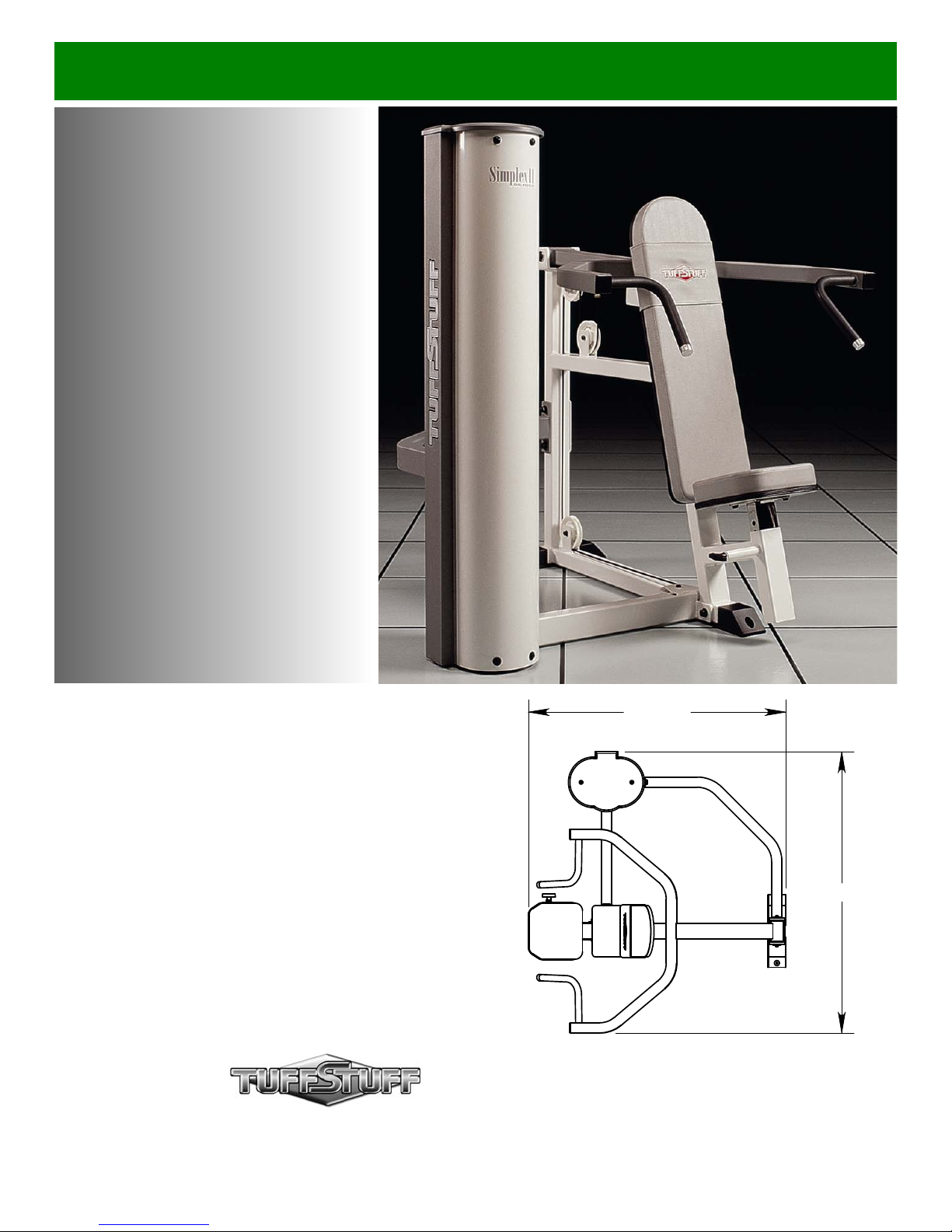
SP-402
Shoulder Press
A m e r i c a ’ s P r e m i e r E x e r c i s e E q u i p m e n t
Revision Date 06-12-02
50 3/4"
55 1/4"
L 50 3/4" W 55 1/4" H 54 3/4"
© 2003 TuffStuff Fitness Equipment, Inc.
SP-402 Rev0
Page 2
Introduction
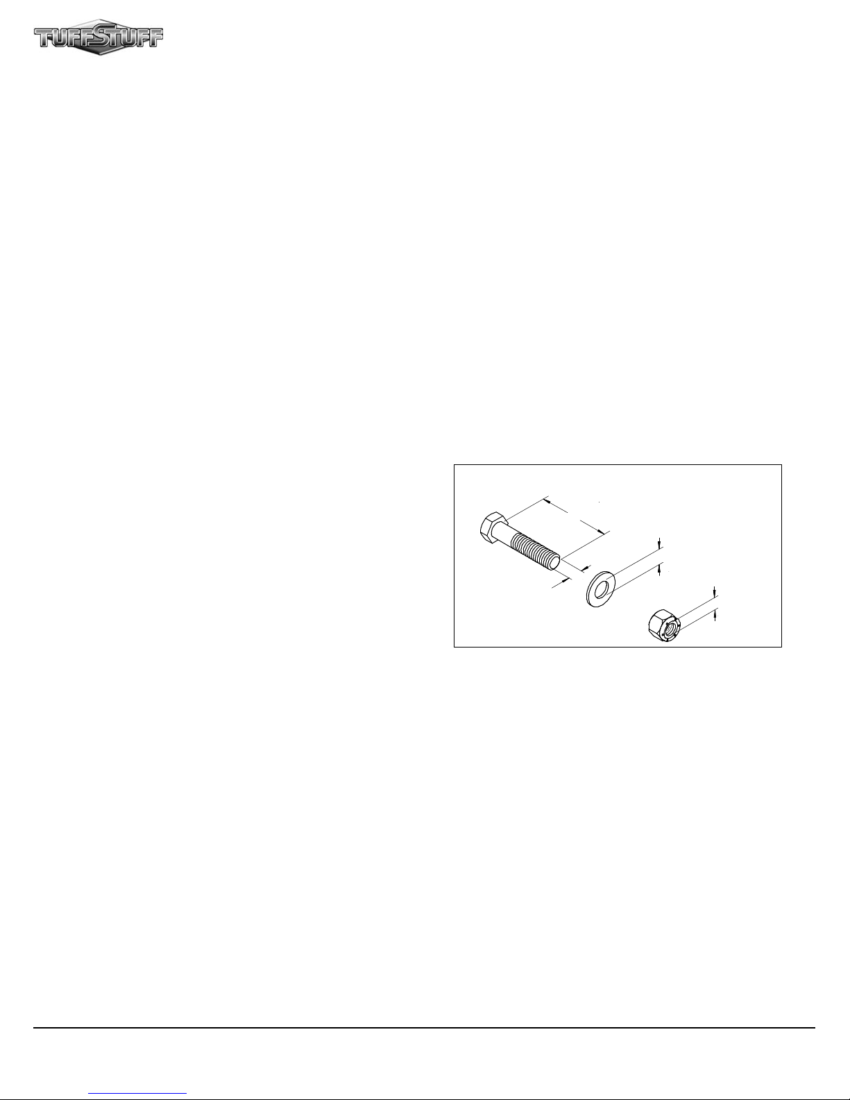
SCREW LENGHT
About the Shoulder Press SP-402
Congratulations on your new purchase of the Shoulder
Press. We hope you are completely satisfied with this
product and wish you many years of enjoyment.
Tuff Stuff Equipment
This Tuffstuff product has been built to precise quality
standards and has been carefully packaged to ensure that
damage will not occur during shipment. The limited lifetime
warranty and signature indicating final inspection has been
conducted by our line foreman, is an expression of our
confidence in the completeness, the materials, and
workmanship of this product.
Warranty
SEE A COPY OF WARRANTY ON BACK PAGE
Registration Card
To avoid unnecessary delays in warranty service and to
insure that a permanent record of your purchase is on file
with our factory, be sure to complete the warranty
registration card and send it to Task Industries today.
Prior to the Assembly of the Shoulder Press
1. We advise you to consult your local Tuff Stuff retailer if
you should have a question or problem regarding the
proper assembly of this unit.
2. Neatly organize and identify all parts according to the
Parts List and the Exploded View Diagram .
Tool Requirements
1. One 3/4” combination wrench
2. One 9/16” combination wrench
3. One 7/16” combination wrench
4. One ratchet
5. One 3/4” socket
6. One 9/16” socket
7. One 7/16” socket
8. Rubber mallet
9. Windex or household glass cleaner
10. One can silicone spray / teflon spray lubricant
11. Measuring tape
12. Utility knife
Specifications
1. Maximum Wt. Capacity - 200 Lbs.
2. Total Machine Weight - 575 Lbs.
3. Footprint (LWH) - See Front Page
Note: Due to continuing product improvements, specifications and designs are subject to change
without notice.
S afety First
Regardless of how enthusiastic you may be about getting on
your equipment and exercising, take the time to ensure that
your safety is not jeopardized. A moment’s lack of attention
can result in an accident, as can failure to observe certain
safety precautions.
1. Read, study and understand the Owner’s Manual and all
the warning labels on this product. Furthermore, it is
recommended to familiarize yourself and others with the
proper operation and workout recommendations for this
Tuff Stuff product prior to use. Some of this information
can be obtained in this Owner’s Manual, as-well-as from
your local Tuff Stuff retailer.
2. It is imperative that you retain this Owner’s Manual and be
sure all warning labels are legible and intact.
Replacement of Owner’s Manuals and labels are available
from your local Tuff Stuff retailer.
3. Consult with your physician before beginning any exercise
program.
Safety Precautions
Hardware Measurement Diagram
WASHER DIAMETER
SCREW WIDTH
4. Use proper discretion when children are present.
5. Frayed or worn cables can be dangerous and may cause
injury. Periodically check these cables for any indication
of wear.
6. Keep hands, limbs, loose clothing and long hair well out of
the way of moving parts.
7. Do not attempt to lift more weight than you can control
safely.
8. Inspect the Unit for any sign of wear on parts, hardware
becoming loose or cracks on welds. If a problem is found,
do not use or allow the machine to be used until the
defective part is repaired or replaced.
NUT DIAMETER
1
SP-402 Shoulder Press
Page 3
Owner’s Manual: Assembly Instructions
39
4
1
1
33
5
33
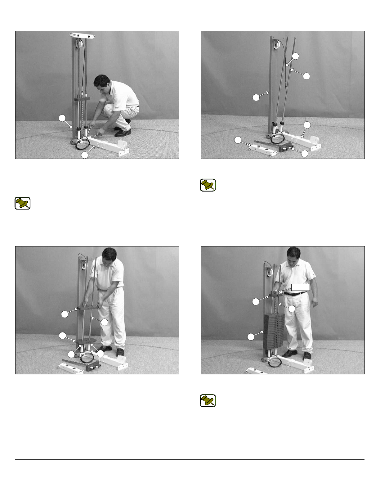
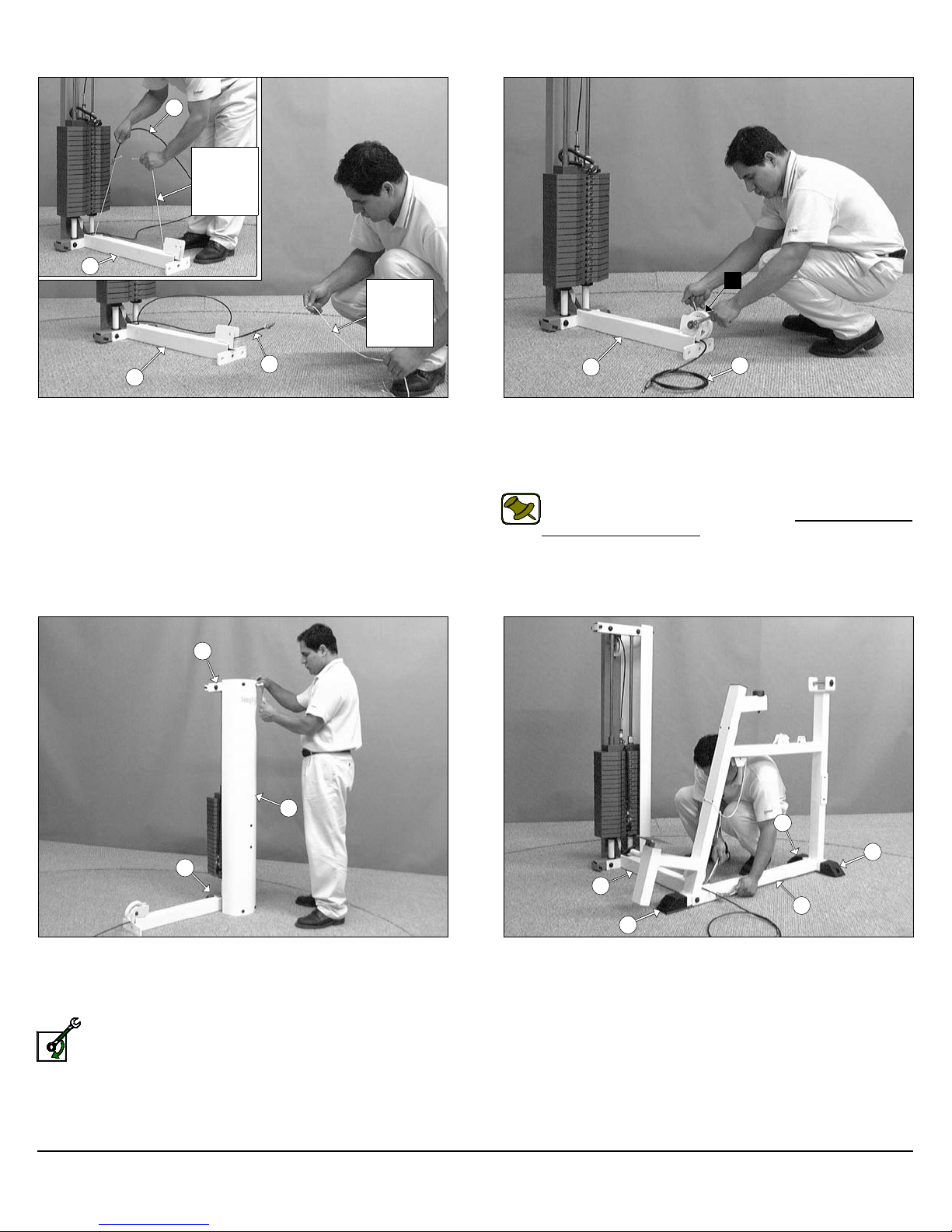
FIG. 1 On a flat surface, attach the Bottom Cross Brace (#33) to
the assembled Weight Stack Frame (#1), in the position as shown
above, and secure it into place using two Hex Head Cap Screws 1/213 X 3 1/2 (#24), four Flat Washers SAE 1/2” (#29), and two Nylon Insert Lock Nuts 1/2-13 (#22).
Note: Use the overhead view on the cover page for designing
your layout before assembling.
8
4
9
FIG. 2 Remove the Guide Rod Retainer (#5), and the Top Plate
Selector Bar (#9) to allow the assembly of the weight plates.
Note: Lubricate the Guide Rods (#4) with silicone or teflon lubricant at this time.
Label
9
4
8
15
FIG. 3 Carefully begin sliding the Weight Plates (#8) onto the
Guide Rods (#4), in position as shown above, allowing the first one
to rest on top of the Rubber Donuts (#15).
15
SP-402 Shoulder Press
8
FIG. 4 Slide the Top Plate Selector Bar (#9) onto the Guide
Rods (#4) allowing it to rest on top of the completed Weight Stack.
Note: Be sure the label on the Top Plate Selector Bar (#9) is
facing out, as shown above, before sliding the Top Plate Se-
lector Bar (#9) onto the Guide Rods (#4).
2
Page 4
1
5
9
68
9
68
4
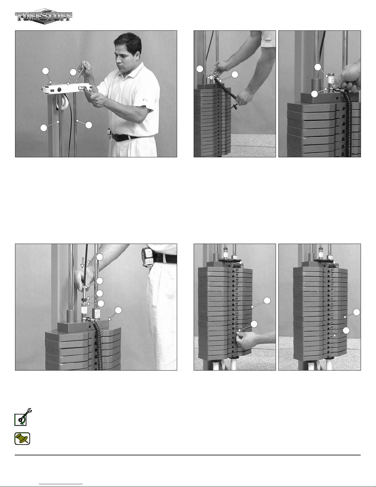
FIG. 5 Maneuver the two Guide Rods (#4) into the holes on the
bottom side of the Guide Rod Retainer (#5). Next, secure the Guide
Rod Retainer (#5) along with the two captive Guide Rods (#4) to the
Weight Stack Frame (#1) using two Hex Head Cap Screws 1/2-13 X
3 1/4 (#65), four Flat Washers SAE 1/2” (#29), and two Nylon Insert
Lock Nuts 1/2-13 (#22).
4
39
58
61
49
9
FIG. 6 Locate the Selector Pin w/Coil (#68) and slide the ring over
the Selector Bar (#9) as shown above.
8
8
FIG. 7 Connect the Cable (#39) to the Top Plate Selector Bar
(#9) by threading the Finished Hex Nut 1/2-13 (#61) and inserting a
Split Lock Washer 1/2” (#49) to the Cable Hex Tap Bolt 1/2-13 X 3
(#58). Then, thread the Cable Hex Tap Bolt 1/2-13 X 3 (#58) to the
threaded socket of the Top Plate Selector Bar (#9).
Loosely Fasten: Do not completely fasten this hardware assembly at this time, as it will be completely fastened later in
the assembly process.
Note: Refer to Fig A on fold-out page 11 for further detailed illustration of this assembly.
3
69
69
FIG. 8 Adhere the Decal Weight Numbers (#69) to the Weight Plates
(#8) in the corresponding order. Begin with the 20 at the top, 30 next,
and so on.
SP-402 Shoulder Press
Page 5
39
Owner’s Manual: Assembly Instructions
Cable
Fishing
String
33
Cable
Fishing
String
39
33
FIG. 9 To facilitate the routing of the Cable (#39) through the Bot-
tom Cross Brace (#33) use the supplied Cable Fishing String. Tie a
knot to the end of the Cable (#39) as shown above. Pull the Cable
Fishing String along with the Cable (#39) through the Bottom Cross
Brace (#33) as shown above. Discard the cable fishing string once
completed with this process.
5
C
33
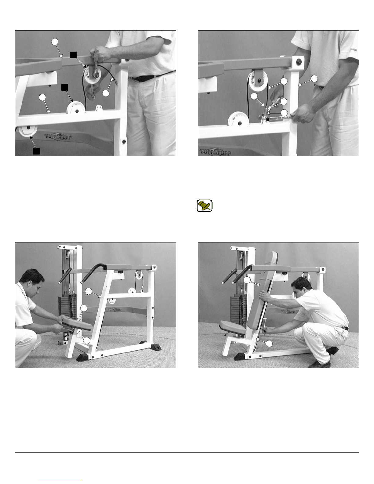
FIG. 10 Attach a Nylon Pulley 4 1/2” Rd. (#16-Labeled C) to the
Bottom Cross Brace (#33), in the position as shown above, and se-
cure it into place using one Hex Head Cap Screw 3/8-16 X 1 3/4
(#27), two Flat Washers SAE 3/8” (#19), and one Nylon Insert Jam
Lock Nut 3/8-16 (#23).
Note: The black boxed letter pointing to the pulleys are used
throughout this manual as reference to the Cable Mapping Diagram on fold-out page 11. These black boxed letters will be
primarily used for locating certain pulleys during the cable routing process beginning with Fig. 10.
39
3
1
FIG. 11 Affix the Weight Shroud w/Plate (#3) to the bottom of the
Weight Stack Frame (#1) and at the top of the Guide Rod Retainer
(#5) using four Hex Head Cap Screws 1/4-20 X 3/4 (#21), and four
Flat Washers 1/4” (#20).
Loosely Fasten: Do not completely fasten this hardware assembly at this time, as it will be completely fastened later in
the assembly process.
SP-402 Shoulder Press
60
60
33
31
60
FIG. 12 Using a rubber mallet, insert three Plastic End Caps 2 X 3
(#60) onto the tube-ends of the Shoulder Press Main Frame (#31).
Next, attach the Shoulder Press Main Frame (#31) to the Bottom
Cross Brace (#33), in the position as shown above, and secur e it into
place using two Hex Head Cap Screws 1/2-13 X 4 3/4 (#57), four Flat
Washers SAE 1/2” (#29), and two Nylon Insert Lock Nuts 1/2-13
(#22).
4
Page 6

30
3
31
31
34
FIG. 13 Attach the Press Bar (#30) to the Shoulder Press Main
Frame (#31) and, using a rubber mallet, insert the Pivot Axle (#32)
through the holes of the Shoulder Press Main Frame (#31) and the
receptacle of the Press Bar (#30) until it is flush with both sides the
Shoulder Press Main Frame (#31). Next, secure the Press Bar
(#30) to the Shoulder Press Main Frame (#31) using two Button
Socket Cap Screws 3/8-16 X 1 (#50), two Chrome Washers 3/8 X 1
1/2 (#47), and two Split Lock Washers 3/8” (#48). Use the two supplied Hex Keys 7/32” (#63) to fasten this assembly.
Cable
Fishing
String
31
39
FIG. 14 Affix the Rear Cross Brace (#34) to the Shoulder Press
Main Frame (#31) using two Hex Head Cap Screws 1/2-13 X 4 3/4
(#57), four Flat Washers SAE 1/2” (#29), and two Nylon Insert Lock
Nuts 1/2-13 (#22). Next, connect the Rear Cross Brace (#34) to the
Weight Shroud w/Plate (#3) using two Hex Head Cap Screws 1/2-13
X 1 (#54), and two Split Lock Washers B/O 1/2” (#56).
Note: Refer to the Exploded View Diagram on fold-out page 10
for further illustration of this assembly.
E
31
39
D
FIG. 15 To facilitate the routing of the Cable (#39) through the tube
of Shoulder Press Main Frame (#31) use the supplied Cable Fish-
ing String. Tie a knot to the end of the Cable (#39). Pull the Cable
Fishing String along with the Cable (#39) through the tube of Shoul-
der Press Main Frame (#31) as shown above. Discard the cable
fishing string once completed with this process.
5
FIG. 16 Insert two Nylon Pulleys 4 1/2 Rd. (#16-Labeled D, E) into
the pulley brackets of the Shoulder Press Main Frame (#31) and s ecure them into place using two Hex Head Cap Screws 3/8-16 X 1 3/4
(#27), four Flat Washers SAE 3/8” (#19), and two Nylon Insert Jam
Lock Nuts 3/8-16 (#23).
Note: Be sure the Cable (#39) is routed properly into the
groove of the Nylon Pulleys.
SP-402 Shoulder Press
Page 7
30
Owner’s Manual: Assembly Instructions
F
E
31
39
D
FIG. 17 Route the Cable (#39) over a Nylon Pulley 4 1/2 Rd. (#16Labeled F) and attach it to the Press Bar (#30) pulley bracket, using
one Hex Head Cap Screw 3/8-16 X 2 (#26), two Flat Washers SAE
3/8” (#19), and one Nylon Insert Jam Lock Nut 3/8-16 (#23).
39
31
63
49
62
FIG. 18 Insert a Split Lock Washer Z/P 1/2” (#49) to the Cable Hex
Bolt 1/2-20 X 1 (#63) then thread the Rod End 1/2-20 (#62) to the Cable Hex Bolt 1/2-20 X 1 (#63). Next, affix the Rod End 1/2-20 (#62) to
the Shoulder Press Main Frame (#31) using one Hex Head Cap
Screw 1/2-13 X 1 1/2 (#55), and one Nylon Insert Jam Lock Nut 1/213 (#64).
Note: Refer to Fig B on fold-out page 11 for further detailed illustration of this assembly.
31
36
35
FIG. 19 Affix the Seat Pad (#36) to the Seat Elevation Tube (#35) ,
in the position as shown above, using four Hex Head Cap Screws
3/8-16 X 1 1/4 (#51), and four Flat Washers SAE 3/8” (#19).
SP-402 Shoulder Press
37
31
FIG. 20 Affix the Back Pad (#37) to the Shoulder Press Main
Frame (#31), in the position as shown above, using four Hex Head
Cap Screws 3/8-16 X 3 (#52), and four Flat Washers SAE 3/8” (#19).
6
Page 8

CABLE ADJUSTMENT
It is imperative that you maintain proper cable adjustment to ensure
a safe and smooth operation.
Caution: The Cable should be inspected and adjusted periodically to avoid any slack in the cable which would, consequently, prevent any damage to the equipment or personal
injury.
39
58
61
9
Cable Adjustment
1. Loosen the Finished Hex Nut 1/2-13 (#61).
2. Thread the Cable Hex Tap Bolt 1/2-13 X 3 (#58) in or out of the
threaded socket of the Top Plate Selector Bar (#9) to give the Cable
(#39) proper tension.
3. Re-tighten the Finished Hex Nut 1/2-13 (#61) to complete the adjustment.
Caution: Make sure the Cable Hex Tap Bolt 1/2-13 X 3 (#58) is
threaded at least 1/2” into the threaded socket of the Top Plate
Selector Bar (#9) once the cable adjustment has been com-
pleted.
49
5
2
FIG. 21 Affix the Weight Shroud (#2) to the bottom of the Weight
Stack Frame (#1) and at the top of the Guide Rod Retainer (#5) us-
ing four Hex Head Cap Screws 1/4-20 X 3/4 (#21), and four Flat
Washers 1/4” (#20).
12
3
2
12
FIG. 22 Insert the two Plastic Shroud Edge Protectors (#12) to both
Shrouds (#2, #3), in the position as shown above, and slide them all
the way down.
7
SP-402 Shoulder Press
Page 9

Owner’s Manual: Assembly Instructions
10
10
2
3
6
12
FIG. 23 Align the edges of both Shrouds (#2, #3) with the grooves
of the Plastic Shroud Gap Cover (#10) and slide it down, as shown
above.
12
11
12
FIG. 24 Connect the two Plastic Shroud Edge Protectors (#12) to
the Plastic Shroud Gap Cover (#10) using the two Plastic Connectors
(#6).
12
2
FIG. 25 Attach the Plastic Shroud Lid (#11) to Guide Rod Retainer
(#5), in the position as shown above, and secure it into place using
two Flat Head Socket Cap Screws 3/8-16 X 3 (#25).
SP-402 Shoulder Press
10
3
8
Page 10

FLAT HEAD SOCKET CAP SCREW B/O 3/8-16 X 3
HEX HEAD CAP SCREW GR-5 B/O 1/2-13 X 3 1/4
DECAL-LARGE TUFFSTUFF LOGO DIAMOND SHAPE
DECAL-FOR BEST PERFORMANCE 1-1/4 X 1-1/2
DECAL-DANGER TIGHTEN THIS RET..., 3/4 X 1-1/2
DECAL-WARNING KEEP HANDS AND FINGERS...
SP-402 Shoulder Press
Parts List
COLOR CHART
GRAY= SUB-ASSEMBLY PARTS
BLACK= HARDWARE
Item No. Description Part No. Qty Item No. Description Part No. Qty
1 WEIGHT STACK FRAME 54" UP0780 1 41 PUSH PULL PIN 1/2 X 5 5/8 BNH0586 1
2 WEIGHT SHROUD 54" UP0781 1 42 RUBBER BUMPER 3/8 X 2-1/2 BNH0511 1
3 WEIGHT SHROUD W/PLATE 54" UP0782 1 43 RUBBER GRIP 1 ID X .125 X 16 BNH0969 2
4 GUIDE ROD 3/4 X 53 5/8 UP0783 2 44 ALUMINUM CAP 1" RD. (CAP-100) BNH0537 2
5 GUIDE ROD RETAINER UP0784 1 45 SOCKET SET SCREW ALLOY 10-32 X 1/8 BNH0473 4
6 PLASTIC SHROUD GAP COVER CONNECTOR BNH1183 2 46 STEEL BUMPER WASHER Z/P 3/8" BNH0498 1
7 WEIGHT STACK SPACER 4" UP0786 2 47 CHROME WASHER 3/8 X 1-1/2 BNH1015 2
8 15 LB WEIGHT PLATE BNH0926 19 48 SPLIT LOCK WASHER B/O 3/8" BNH0658 2
9 10 LB TOP PLATE W/ADJ. SLTR BAR 19 WTS BNH1100 1 49 SPLIT LOCK WASHER Z/P 1/2" BNH0572 2
10 PLASTIC SHROUD GAP COVER 27" LONG BNH1083 1 50 BUTTON HEAD SOCKET CAP SCREW B/O 3/8-16 X 1 BNH0115 2
11 PLASTIC SHROUD LID 5/8 X 14-1/8 X 10 BNH0185 1 51 HEX HEAD CAP SCREW GR-5 B/O 3/8-16 X 1-1/4 BNH0273 4
12 PLASTIC SHROUD EDGE PROTECTOR 1/8 X 27 BNH0599 2 52 HEX HEAD CAP SCREW GR-5 B/O 3/8-16 X 3 BNH0282 5
13 EDGE PROTECTOR GRAY 54" BNH1148 2 53 PLASTIC INSERT CAP 2" SQ. BNH0012 2
14 URETHANE BUMPER 1 3/4 BNH0229 3 54 HEX HEAD CAP SCREW GR-5 B/O 1/2-13 X 1 BNH0259 2
15 RUBBER DONUT 3/4 X 2 1/2 BNH0068 2 55 HEX HEAD CAP SCREW GR-5 B/O 1/2 13 X 1 1/2 BNH0727 1
16 NYLON PULLEY 4 1/2 RD. WHITE BNH0556 6 56 SPLIT LOCK WASHER B/O 1/2" BNH0653 2
17 U-STYLE TAPPED HOLE NUT 1/4-20 BNH0708 8 57 HEX HEAD CAP SCREW GR-5 B/O 1/2-13 X 4-3/4 BNH0895 4
18 FLAT WASHER USS B/O 3/4 X 2" BNH0878 4 58 CABLE HEX TAP BOLT Z/P 1/2-13 X 3 BNH1048 1
19 FLAT WASHER SAE B/O 3/8" BNH0239 24 59 PLASTIC INSERT CAP 2 X 3 BNH0052 2
20 FLAT WASHER SAE B/O #12 (1/4") BNH0877 8 60 PLASTIC END CAP 2 X 3 (SIMPLEX) BNH0606 3
21 HEX HEAD CAP SCREW GR-5 B/O 1/4-20 X 3/4 BNH0890 8 61 FINISHED HEX NUT B/O 1/2-13 BNH0201 1
22 NYLON INSERT LOCK NUT B/O 1/2-13 BNH0212 8 62 ROD END 1/2-20 BNH0674 1
23 NYLON INSERT JAM LOCK NUT B/O 3/8-16 BNH0365 7 63 CABLE HEX BOLT GR-8 Z/Y 1/2-20 X 1 BNH1045 1
24 HEX HEAD CAP SCREW GR-5 B/O 1/2-13 X 3-1/2 BNH0263 2 64 NYLON INSERTJAM LOCK NUT B/O 1/2-13 BNH0366 1
25
26 HEX HEAD CAP SCREW GR-5 B/O 3/8-16 X 2 BNH0279 2 66 HEX KEY 3/32" BNH0372 1
27 HEX HEAD CAP SCREW GR-5 B/O 3/8-16 X 1-3/4 BNH0274 4 67 HEX KEY 7/32" BNH0575 1
28 RUBBER GROMMET 3/4" ID (2867-012) BNH0401 2 68 SELECTOR PIN W/COIL DOUBLE LOCK UP0466 1
29 FLAT WASHER SAE B/O 1/2" BNH0238 16 69 DECAL-NUMBERS 20-200 LBS. SET BNH1202 1
30 PRESS BAR UP0838 1 70 U-STYLE TAPPED HOLE NUT 3/8-16 BNH1211 2
31 SHOULDER PRESS MAIN FRAME UP0839 1 71 DECAL-SIMPLEX II (1 7/8 X 5 3/16) BNH1199 1
32 PIVOT AXLE UP0807 1 72 DECAL-TUFFSTUFF (2 3/4 X 19 1/16) BNH1200 1
33 BOTTOM CROSS BRACE UP0989 1 73 DECAL-EXERCISE SP-402 SHOULDER PRESS BNH1187 1
34 REAR CROSS BRACE UP0836 1 74
35 SEAT ELEVATION TUBE UP0837 1 75 DECAL-ADJUST CABLE HERE BNH0789 1
36 SEAT PAD UP0840 1 76
37 BACK PAD UP0841 1 77
38 WEAR COVER (OPTIONAL) UP0825 1 78 DECAL-CAUTION 1 3/4 X 5-1/2 HORIZONTAL BNH0126 1
39 SHOULDER PRESS CABLE UP0859 1 79
40 BALL BEARING #W 516 BNH0628 2 80 SUPER LUBE TEFLON LUBRICANT 82340 BNH0704 2
BNH0787 2 65
BNH0576 2
BNH0360 1
BNH0143 1
BNH0142 1
BNH0620 1
9
SP-402 Shoulder Press
Page 11

DO NOT DISCARD THIS MANUAL
LIMITED WARRANTY
TuffStuff warrants to the original purchaser only that TuffStuff equipment will be free from defects in
material and workmanship. The warranty and remedies set forth herein are conditioned upon proper
storage, installation, use, maintenance and conformance with any recommendations of TuffStuff. This
warranty does not cover products not manufactured by TuffStuff or products which are altered without
the express written consent of TuffStuff. This warranty as specified: a) Frame structure and welds —
Lifetime, b) Moving parts (e.g. pulleys, bearings, bushings) — 5 years; c) Cables upholstery, handgrips, finish and any miscellaneous parts not listed — 1 year; from the day of delivery to the original
purchaser. The obligation of TuffStuff under this warranty is limited to repairing or replacing warranted
defective parts, as TuffStuff may elect, at TuffStuff’s facility in Pomona, California, without charge to
purchaser for either parts or labor. Purchaser is responsible for installation of repaired or replaced
parts, and all transportation and insurance costs on returned or replaced equipment to and from
TuffStuff’s facility in Pomona.
THE FORGOING SHALL CONSTITUTE THE SOLE REMEDY OF THE PURCHASER AND THE
SOLE LIABILITY OF TUFFSTUFF WITH REGARD TO WARRANTY. NO IMPLIED STATUTORY
WARRANTY OF MERCHANTABILITY OR FITNESS FOR A PARTICULAR PURPOSE SHALL APPLY. IN NO EVENT, WHETHER AS A RESULT OF BREACH OF CONTRACT, WARRANTY, NEGLIGENCE OR OTHERWISE, SHALL TUFFSTUFF BE LIABLE FOR SPECIAL, INCIDENTAL OR
CONSEQUENTIAL DAMAGES INCLUDING, BUT NOT LIMITED TO, LOSS OF PROFITS OR
REVENUE, LOSS OF USE OF EQUIPMENT, COST OF CAPITAL, COST OF SUBSTITUTION
EQUIPMENT, DOWNTIME COST, OR CLAIMS OF CUSTOMERS OR PURCHASER FROM SUCH
DAMAGE.
This warranty is the final, complete and exclusive agreement of the parties with respect to the quality
or performance of the equipment and no action for breach of this written warranty or any implied warranty shall be commenced more than one (1) year after the accrual of the cause of action. No modification of this warranty or waiver of its terms shall be binding on either party unless approved in writing
by an authorized representative of the party. Contact TuffStuff at 1325 E. Franklin Avenue, Pomona,
California 91766, before returning any defective equipment.
Note: Retain your sales receipt and be sure to mail in the warranty registration card to insure that a
permanent record of your purchase is on file with the factory and to avoid unnecessary delays in
warranty service.
TuffStuff Fitness Equipment, Inc.
1325 E. Franklin Avenue
Pomona, CA 91766, USA
Ph: 909-629-1600 Fax: 909-629-4967
E-mail: service@tuffstuff.net Net: www.tuffstuff.net
 Loading...