

Page 1
ASSEMBLY INSTRUCTIONS
TABLE OF CONTENTS:
Introduction
Pg. 2
Safety Precautions
Pg. 3 - Pg. 4
Assembly Instructions
Pg. 5 - Pg. 9
SBU-400 Exploded View Diagram
Pg. 10
SHS-410 Exploded View Diagram
Pg. 11
SLS-420 Exploded View Diagram
Pg. 12
Decal Placement
Pg. 13
Decal Reference
Pg. 14
Warranty
Back Page
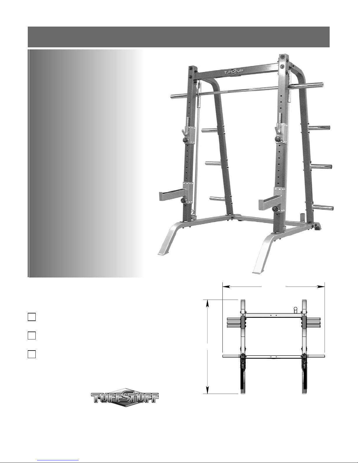
Smith-Half Cage Series
Includes Assembly for:
SBU-400
Base Unit Kit
SHC-410
Half Cage Conversion Kit
SLS-420
Linear Bearing Press System Kit
Revision Date 05-10-06
76 1/2"
70 1/2"
America’s Premier Exercise Equipment
L 70 1/2" W 76 1/2" H 82 1/2"
SBU-400 Rev1
Page 2
About the Smith-Half Cage Series
Congratulations on your new purchase of the Smith-Half Cage
Series. This gym is capable of a variety of different exercises, aswell-as, smooth and user-friendly adjustment features. In addition,
this gym has been designed to meet the needs and performance
requirements for a suitable home exercise machine. We hope you
are completely satisfi ed with this product and wish you many years
of enjoyment.
TuffStuff Equipment
This Tuffstuff product has been built to precise quality standards
and has been carefully packaged to ensure that damage will not
occur during shipment. The Home Lifetime Warranty and signature
indicating fi nal inspection has been conducted by our line foreman,
is an expression of our confi dence in the completeness, the
materials, and workmanship of this product.
Assembly Notes
1. Read and follow each step of this Assembly Instruction Manual
in sequence. Do not skip ahead, as it will result in an improper
assembly or in having to disassemble parts later.
Prior to the Assembly of the Smith-Half Series
1. We advise you to consult your local TuffStuff retailer if you should
have a question or problem regarding the proper assembly of
this unit.
2. Consider the complete surface area of the Smith-Half Cage
Series. Use the overhead view located on the front page for
designing your layout before assembling. Once the Smith-Half
Cage Series has been fully assembled it will be heavy and
diffi cult to move, therefore you should assemble the unit in the
area where it is to be used upon completion.
Warranty
SEE A COPY OF WARRANTY ON BACK PAGE.
Registration Card
To avoid unnecessary delays in warranty service and to insure that
a permanent record of your purchase is on fi le with our factory,
be sure to complete the warranty registration card and send it to
TuffStuff Fitness Equipment today.
Specifi cations
SBU-400 SHC-410 SLS-420
1. Maximum Wt. Capacity N/A 400 lbs. 300 lbs.
2. Total Machine Weight 220 lbs. 40 lbs. 80 lbs.
3. Footprint (LWH) - See Front Cover
Note: Due to continuing product improvements, specifi cations and designs are subject to change
without notice.
3. It is recommended that another person assist you with the
assembly of this unit.
4. Neatly organize and identify all parts according to the Parts List
and the Exploded View Diagrams.
Tool Requirements
1. One 3/4” combination wrench
2. One 9/16” combination wrench
3. One ratchet
4. One 3/4” socket
5. One 9/16” socket
6. One rubber mallet
7. Measuring tape
8. Utility knife
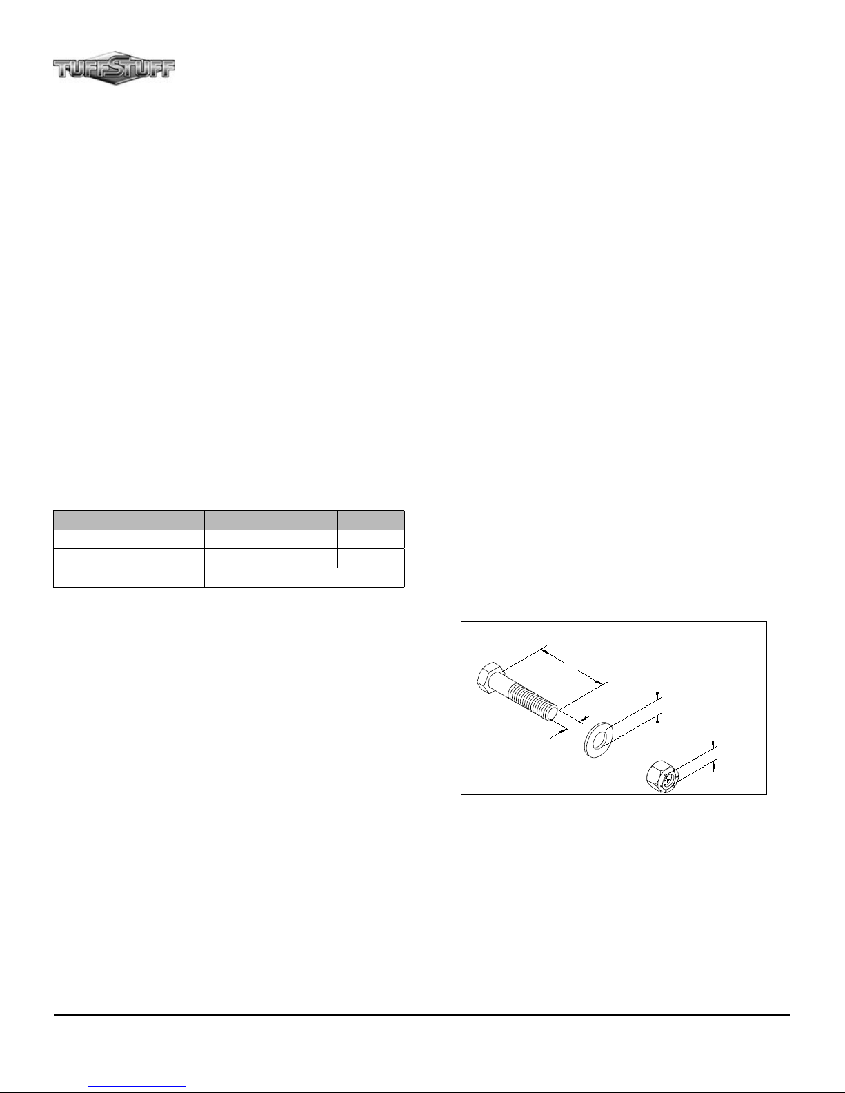
Hardware Measurement Diagram
H
T
G
N
E
L
W
E
R
C
S
R
E
H
S
A
W
H
T
D
I
WW
E
R
C
S
R
E
T
E
M
A
I
D
R
E
T
E
M
A
I
D
T
U
N
2
Smith-Half Cage Series
Page 3
Safety Precautions
Safety First
Regardless of how enthusiastic you may be about getting on your
equipment and exercising, take the time to ensure that your safety is not
jeopardized. A moment’s lack of attention can result in an accident, as
can failure to observe certain simple safety precautions.
3
1. Read, study and understand the Assembly Instructions and all the
warning labels on this product. Furthermore, it is recommended to
familiarize yourself and others with the proper operation and workout
recommendations for this TuffStuff product prior to use. Some of
this information can be obtained in this Assembly Instructions, aswell-as from your local TuffStuff Retailer.
2. It is imperative that you retain this Assembly Instructions and be
sure all warning labels are legible and intact. Replacement of the
Assembly Instructions and labels are available from your local
TuffStuff Retailer.
3. Consult with your physician before beginning any exercise
program.
4. Use proper discretion when children are present.
5. Keep hands, limbs, loose clothing and long hair well out of the way
of moving parts.
6. Do not attempt to lift more weight than you can control safely.
7. Inspect the Smith-Half Cage for any sign of wear on parts, hardware
becoming loose or cracks on welds. If a Problem is found do not
use or allow the machine to be used until defective part is repaired
or replaced.
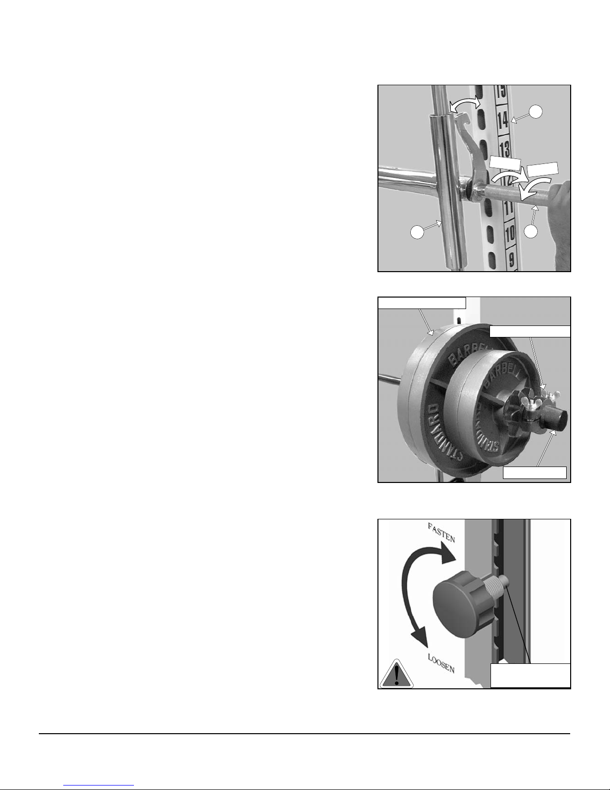
8. The Press Bar (#12) has a swivel locking mechanism that allows
you to safely lock out the Press Bar (#12) at virtually any setting.
See Fig. A.
Lock
11
Fig. A Illustration above depicts the Press Bar
(#12) locking mechanism.
Barbell Weight Plates
Olympic Bar Collar
Fig. B Caution: Use collars to prevent the weight
plates from falling off the Olympic Adaptors (#10).
Unlock
12
Weight Prong
9. If you are adding or storing weight plates on the Olympic Adapters
(#10), do not over-load them. Allow enough space for weight collars.
See Fig. B
10. Pay special attention to the Turn/ Pull Pins w/Knob (#134) located
on the Bar Holders (#9) and the Bar Safety Spotters (#7, #8). Be
sure they are fully engaged into the selectorized holes of the Front
Uprights (#3). Refer to Fig. C for further illustration.
Smith-Half Cage Series
Turn/Pull Pin w/Knob
Fully Engaged
Fig. C Caution: Check that all Turn/Pull Pins
w/Knob (#134) to be fully engaged into the selected
holes of the Front Uprights (#3).
3
Page 4
Safety Precautions
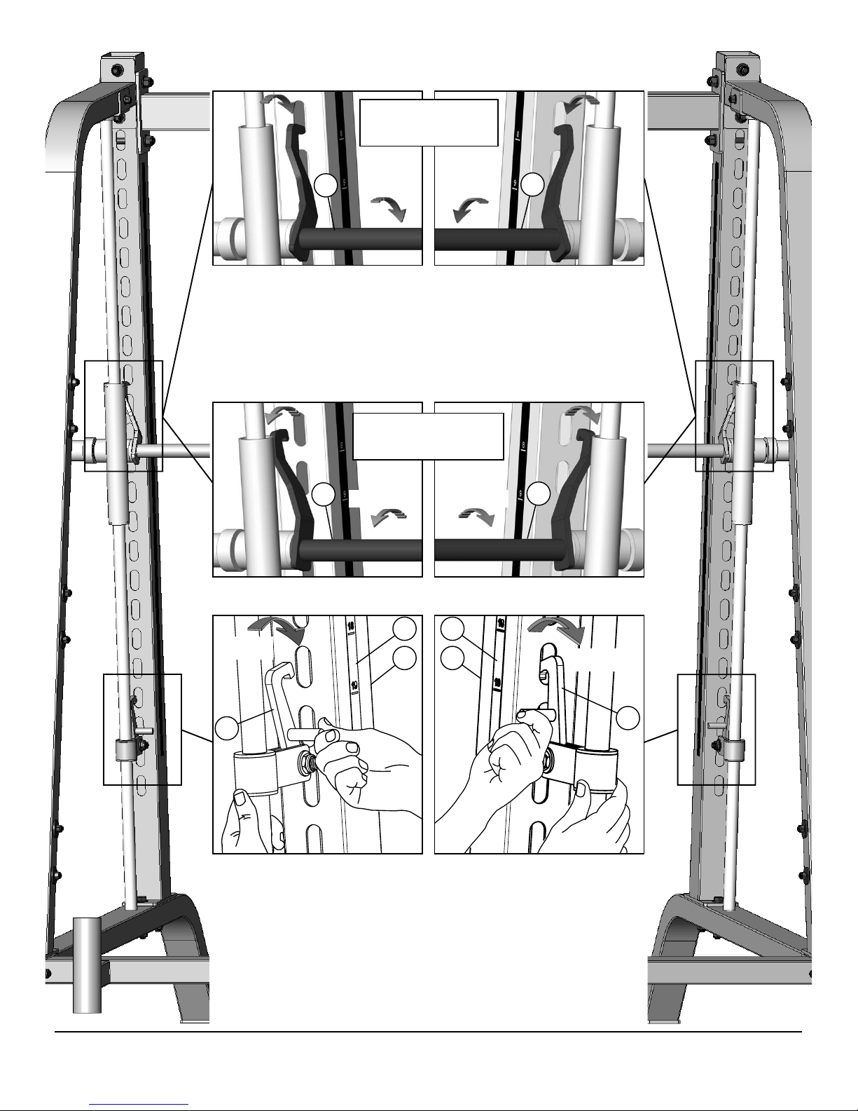
Press Bar
Correctly Engaged
12
Locking Locking
11. DANGER: Once the unit is completely assembled take the time to ensure
that the unit is assembled correctly square and perpendicular. Pay special
attention to the Press Bar (#12) making sure both hooks engage uniformly and
completely into each locking position. If both of the Press Bar Hooks are not
engaging uniformly into the receptacle holes, it will be necessary to loosen
some frame hardware then re-align the frame and re-tighten the hardware.
If Problem persists, Do Not Use the Machine and contact your TuffStuff
Retailer.
12
Disengaged Press Bar
During Exercise
12
Unlocking Unlocking
12. The illustrations above depict the Press Bar disengaged setting which is used
during exercise.
12
58 58
Locking
14
13. DANGER: The Safety Spotter Hooks (#14, #15) prevent the Press Bar from
being lowered below required point and avoid getting crushed under the Press
Bar (#12) if the weight is too heavy to control. Use the Decal-numbers (#58)
on the Front Uprights (#3) to ensure that the Safety Spotter Hooks (#14,#15)
are set to an equal adjustment setting (same height).
Before you add weight plates to the Press Bar (#12), you must fi rst set-up the
Safety Spotter Hooks (#14,#15) for the required exercise. It is recommended
that you test the desired setting without weight plates on the Press Bar (#12)
to make sure the Safety Spotter Hooks (#14,#15) are set to the appropriate
exercise setting.
3 3
Unlocking
15
4
Smith-Half Cage Series
Page 5
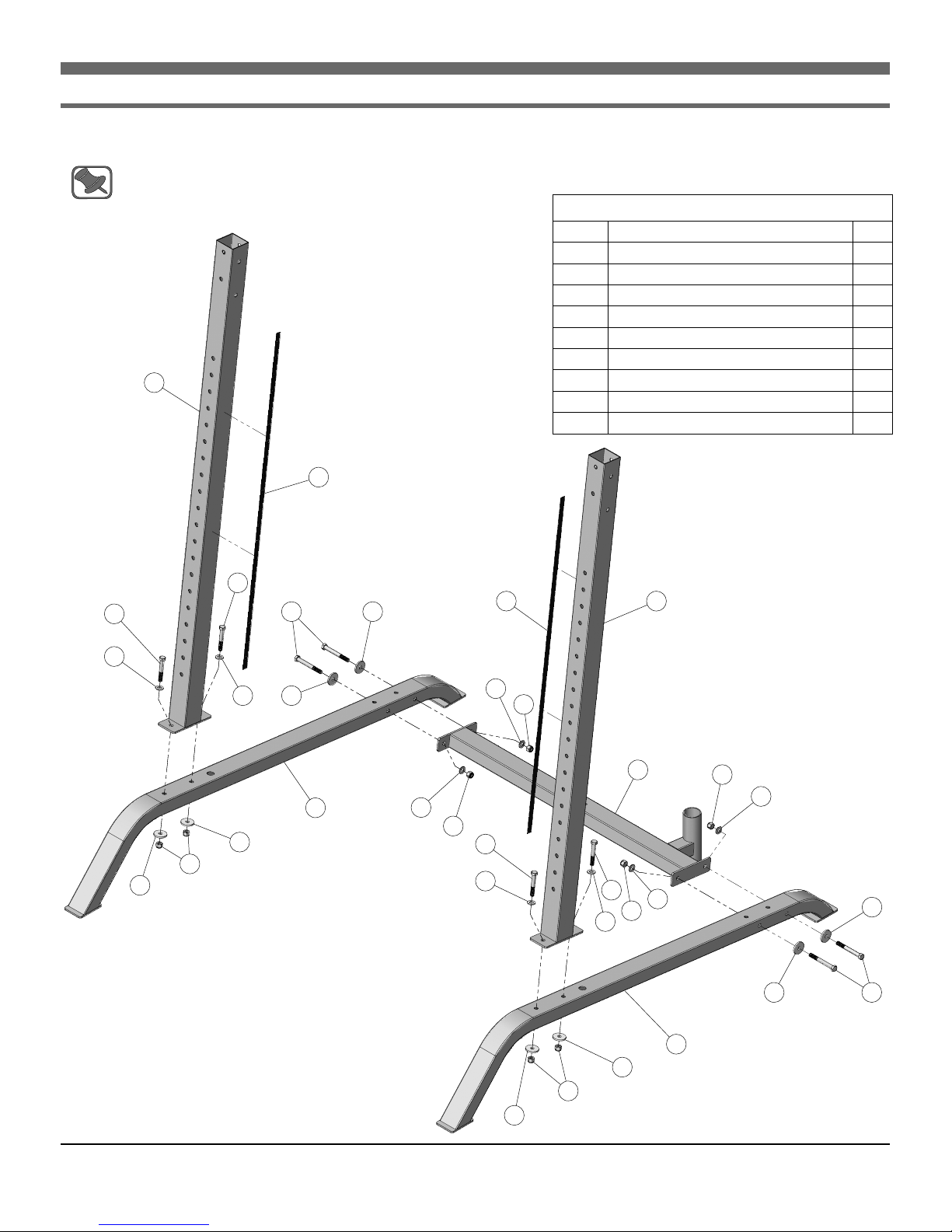
Step 1 Assembling Base Unit
A. Locate the two Bottom Side Frames (#2) and attach them to the Bottom Cross Brace (#1) using hardware shown.
B. Attach the two Front Uprights (#3) to the two Bottom Side Frames (#2) using hardware shown.
Note: Make sure to assemble the Front Uprights (#3) with the oval hole pattern towards the back of the Unit, and the
Decal-Numbers (#58) towards the inside of the Unit.
Assembly List
Item # Description Qty.
1 BOTTOM CROSS BRACE 1
2 BOTTOM SIDE FRAME 2
3 FRONT UPRIGHT 2
58 DECAL-NUMBERS 1-20 TEFLON 2
65 FLAT WASHER 1/2 X 1 3/4 8
67 FLAT WASHER SAE 1/2” 8
3
58
72 HEX HEAD CAP SCREW 1/2-13 X 3 1/4 4
74 HEX HEAD CAP SCREW 1/2-13 X 4 1/4 4
101 NYLON INSERT LOCK NUT 1/2-13 8
72
72
67
67
65
101
65
74
65
2
65
67
101
58 3
67
101
72
67
72
67
101
1
67
101
67
65
65
74
Smith-Half Cage Series
2
65
101
65
5
Page 6

Step 2 Assembling the Half Cage Conversion Kit (SHC-410)
A. Slide the two Bar Safety Spotters (#7, #8) onto the Front Uprights (#3).
B. Slide the two Bar Holders (#9) onto the Front Uprights (#4).
Item # Description Qty.
7 LEFT SIDE BAR SAFETY SPOTTER 1
8 RIGHT SIDE BAR SAFETY SPOTTER 1
9 BAR HOLDER 2
63 FLAT PHILLIPS SCREW 8-32 X 1/4 4
134 TURN/PULL PIN W/KNOB AND LOCK 4
9
63
134
3
Assembly List
3
134
8
63
9
7
6
Smith-Half Cage Series
Page 7

Step 3 Assembling the Press Bar (SLS-420)
A. Insert the Linear Shafts 1 X 69 11/16 (#13) into the receptacles of the Bottom Side Frames (#2).
B. Insert the Safety Spotter Assemblies (#14, #15) onto the Linear Shafts (#13).
Caution: It is strongly recommended to use another person in assisting with the following assembly.
C. Align the Chrome Press Bar Housings (#11) with the Linear Shafts (#13) and carefully begin sliding the Chrome Press
Bar Assembly (#12) onto the Linear Shafts (#13).
Assembly List
Item # Description Qty.
12 CHROME PRESS BAR ASSEMBLY 1
13 LINEAR SHAFT 1 X 69 11/16 2
13
11
12
14 LEFT SAFETY SPOTTER ASSEMBLY 1
15 RIGHT SAFETY SPOTTER ASSEMBLY 1
13
15
14
2
2
11
Smith-Half Cage Series
7
Page 8

Step 4 Assembling the Rear Side Supports
A. Attach the two Shaft Retainer Brackets (#17) to the Linear Shafts (#13).
B. Affi x the two Rear Side Supports (#5) to the two Bottom Side Frames (#2) using hardware shown.
C. Affi x the two Rear Side Supports (#5) to the two Front Uprights (#3) using hardware shown.
D. Secure the two Shaft Retainers Brackets (#17) along with the two confi ned Linear Shafts (#13) to the Rear Side
Supports (#5) using hardware shown.
Assembly List
Item # Description Qty.
5 REAR SIDE SUPPORT 2
17* SHAFT RETAINER BRACKET 2
101
67
84
68
65
17
74
13
65
3
101
67
68
102
102
5
68
74
65
101
67
65 FLAT WASHER 1/2 X 1 3/4 8
67 FLAT WASHER SAE 1/2” 8
68* FLAT WASHER SAE 3/8” 4
72 HEX HEAD CAP SCREW 1/2-13 X 3 1/4 4
74 HEX HEAD CAP SCREW 1/2-13 X 4 1/4 4
84* HEX HEAD CAP SCREW 3/8-16 X 4 2
101 NYLON INSERT LOCK NUT 1/2-13 8
102* NYLON INSERT LOCK NUT 3/8-16 2
* Items Required Only for SLS-420
101
67
17
72
67
65
101
65
68
84
13
72
67
101
65
5
72
67
65
8
Smith-Half Cage Series
Page 9

Step 5 Assembling the Top Cross Brace and the Olympic Adapters
A. Attach the Top Cross Brace (#6) to the Front Uprights (#3) using hardware shown.
B. Insert Plastic Insert Caps 1 7/8” Rd. (#110) into the tube-ends of the Olympic Adapters w/Plate (#4).
C. Attach the six Olympic Adapters w/Plate (#4) to the two Rear Side Supports (#5) using hardware shown.
Assembly List
Item # Description Qty.
67
101
65
74
84
68
65
3
110
110
84
68
4
84
68
84
68
4
6
101
67
51
102
101
67
51
102
65
74
51
102
102
6TOP CROSS BRACE 1
4OLYMPIC ADAPTER W/PLATE 6
51 CHROME WASHER 3/8 X 1 1/2 12
65 FLAT WASHER 1/2 X 1 3/4 4
67 FLAT WASHER SAE 1/2” 4
68 FLAT WASHER SAE 3/8” 12
74 HEX HEAD CAP SCREW 1/2-13 X 4 1/4 4
84 HEX HEAD CAP SCREW 3/8-16 X 4 12
101 NYLON INSERT LOCK NUT 1/2-13 4
102 NYLON INSERT LOCK NUT 3/8-16 12
110 PLASTIC INSERT CAP 1 7/8” RD. 6
65
74
102
5
68
102
51
4
68
51
51
102
84
84
110
Smith-Half Cage Series
68
84
4
68
84
110
9
Page 10

65
74
74
72
67
65
65
SBU-400 Exploded View Diagram
101
58
65
84
74
2
110
68
67
84
65
65
67
72
67
68
101
101
67
101
6
101
67
101
74
67
65
65
58
67
67
72
3
72
67
67
101
5
64
133
101
4
72
67
51
102
51
67
101
65
67
101
1
101
67
65
65
67
102
51
72
67
67
74
54
101
5
101
51
65
72
67
68
4
68
84
110
84
65
3
72
67
65
101
65
74
CHART
65
SBU-400
101
65
65
101
65
2
BOLD FONT = SUB-ASSEMBLY PARTS
REGULAR FONT = HARDWARE
ITEM # DESCRIPTION PART # QTY. ITEM # DESCRIPTION PART # QTY.
1 BOTTOM CROSS BRACE UP3482 1
2 BOTTOM SIDE FRAME UP3481 2
3 FRONT UPRIGHT UP3483 2
4OLYMPIC ADAPTER W/PLATE UP2202 6
5 REAR SIDE SUPPORT UP3484 2
6TOP CROSS BRACE UP3485 1
51 CHROME WASHER 3/8 X 1 1/2 BNH1015 12 102 NYLON INSERT LOCK NUT 3/8-16 BNH0214 12
54 DECAL-CAUTION 1 3/4 X 5 1/2 BNH0126 1 110 PLASTIC INSERT CAP 1 7/8” RD. BNH0003 6
58 DECAL-NUMBERS 1-20 TEFLON BNH1547 2 133 TUFFSTUFF LOGO ALUMINUM (LG) BNH1324 1
64 FLAT PHILLIPS SCREW ZINC # 5 X 1/2 BNH1481 2 139 DECAL-REFERENCE LEFT SIDE ( L ) BNH1850 1
65 FLAT WASHER 1/2 X 1 3/4 BNH0241 20 140 DECAL-REFERENCE RIGHT SIDE ( R ) BNH1851 1
Parts List
67 FLAT WASHER SAE 1/2” BNH0238 20
68 FLAT WASHER SAE 3/8” BNH0239 12
72 HEX HEAD CAP SCREW GR-5 B/O 1/2-13 X 3 1/4 BNH0576 8
74 HEX HEAD CAP SCREW GR-5 B/O 1/2-13 X 4 1/4 BNH0291 12
84 HEX HEAD CAP SCREW GR-5 B/O 3/8-16 X 4 BNH0285 12
101 NYLON INSERT LOCK NUT 1/2-13 BNH0212 20
10
Smith-Half Cage Series
Page 11

SHC-410 Exploded View Diagram
107
9
118
134
134
63
63
107
8
9
7
CHART
BOLD FONT = SUB-ASSEMBLY PARTS
REGULAR FONT = HARDWARE
ITEM # DESCRIPTION PART # QTY. ITEM # DESCRIPTION PART # QTY.
7 LEFT SIDE BAR SAFETY SPOTTER UP3487 1
8 RIGHT SIDE BAR SAFETY SPOTTER UP3486 1
9 BAR HOLDER UP3488 2
63 FLAT PHILLIPS MACHINE SCREW 8-32 X 1/4 BNH0408 4
Smith-Half Cage Series
SHC-410
Parts List
107 NYLON STEM BUTTON 12.5 mm X 26 mm X 9.5 mm BNH0547 64
118 RUBBER CORR MAT 1/8 X 1 7/8 X 15 1/2 BNH1247 2
134 TURN/PULL PIN W/KNOB AND LOCK BNH0989 4
11
Page 12

84
68
17
92
11
13
90
68
102
SLS-420 Exploded View Diagram
102
68
17
68
84
13
90
92
71
15
CHART
67
98
67
99
98
16
92
90
12
108
14
89
99
16
98
11
95
92
67
SLS-420
90
98
67
95
89
48
10
122
88
71
BOLD FONT = SUB-ASSEMBLY PARTS
REGULAR FONT = HARDWARE
ITEM # DESCRIPTION PART # QTY. ITEM # DESCRIPTION PART # QTY.
10 CHROME OLYMPIC ADAPTER UP0679 2
11 CHROME PRESS BAR HOUSING UP0680 2
12 CHROME PRESS BAR W/HOOKS UP0678 1
13 LINEAR SHAFT 1 X 69 11/16 UP3489 2
14 SAFETY HOOK LT UP0525 1
15 SAFETY HOOK RT UP0524 1
16 SAFETY SPOTTER BRACKET UP0523 2
17 SHAFT RETAINER BRACKET UP3490 2
48 BRONZE BUSHING 1 1/8 X 1 11/32 X 3/4 BNH0735 2 122 SHOULDER BOLT 14 mm X 14 mm THREAD 1/2-13 BNH0426 2
67 FLAT WASHER SAE 1/2” BNH0238 4 136 DECAL-FOR BEST PERFORMANCE 1 1/4 X 1 1/2 BNH0143 2
68 FLAT WASHER SAE 3/8” BNH0239 4 137 DECAL-DANGER ENGAGE SAFETY SPOTTER 1.5 X 1 BNH1848 4
71 HEX HEAD CAP SCREW 1/2-13 X 1 1/2 BNH0727 2 138 DECAL-DANGER ENGAGE SAFETY SPOTTER 1.75 X 4 BNH1849 4
84 HEX HEAD CAP SCREW GR-5 B/O 3/8-16 X 4 BNH0285 2 139 DECAL-REFERENCE LEFT SIDE ( L ) BNH1850 1
88 HEX KEY M14 BNH1303 1 140 DECAL-REFERENCE RIGHT SIDE ( R ) BNH1851 1
12
Parts List
89 INTERNAL RETAINING RING 1 7/16” BNH1308 4
90 INTERNAL RETAINING RING 1 9/16” BNH0095 4
92 LINEAR BEARING BNH0770 4
95 NEEDLE-ROLLER BEARING (HMK-2830) BNH1307 4
98 NYLON BUSHING 1 X 1 1/2 BNH0531 4
99 NYLON INSERT JAM LOCK NUT 1/2-13 BNH0366 2
102 NYLON INSERT LOCK NUT 3/8-16 BNH0214 2
108 NYLON WASHER 1 1/8 X 2 X 1/4 BNH0388 2
Smith-Half Cage Series
Page 13

Decal Placements
54
BNH0126
CENTERED, 52" FROM BOTTOM
EDGE OF THE TUBE.
5
52"
VERTICALLY AND HORIZONTALLY
CENTERED ALONG THE TUBE.
BNH1324
8 1/2"
64
133
BNH1547
CENTERED, 8 1/2" DOWN
FROM TOP OF THE TUBE.
58
6
8 1/2"
BNH1849
CENTERED TO THE SIDE OF THE TUBE,
1/2" DOWN FROM TOP OF THE TUBE.
(BOTH SIDES)
BNH0143
CENTERED ON FRONT
OF THE TUBE
R
140
137
15
1/2"
136
11
137
138
16
14
138
BNH1848
CENTERED ON PLATE.
(BOTH SIDES)
137
3
16
BNH1848
CENTERED ON PLATE.
(BOTH SIDES)
CENTERED ON FRONT
139
BNH0143
OF THE TUBE.
R
1/2"
136
138
58
3
140
R
139
L
11
L
138
BNH1849
CENTERED TO THE SIDE OF THE TUBE,
1/2" DOWN FROM TOP OF THE TUBE.
(BOTH SIDES)
Smith-Half Cage Series
13
Page 14

Decal Reference
54
BNH0126
DANGER
!
Engage this Safety
Spotter Hook PRIOR to
performing the exercise
137
BNH1848
!
DANGER
Engage the Safety
Spotter Hook to the
required stop position
for each exercise.
Failure to comply
would allow this press
bar to drop beyond
your own capability
and could result in
serious injury to you.
138
BNH1849
139
BNH1850
133
BNH1324
140
BNH1851
SCALE 1 : 2
14
136
BNH0143
58
BNH1547
Smith-Half Cage Series
Page 15

DO NOT DISCARD THIS MANUAL
HOME LIFETIME WARRANTY
TuffStuff products are warranted to the retail purchaser to be free from defects in materials and workmanship.
TuffStuff exclusive Home Lifetime Warranty coverage extends for the life of the product while owned by the
original retail purchaser, and used only in a home or residential setting unless otherwise noted in the owner’s
manual.
This warranty does not cover:
1. TuffStuff products sold for and used in a commercial or institutional setting.
2. Any damage, failure or loss caused by accident, misuse, neglect, abuse, improper assembly, improper
maintenance, or failure to follow instructions or warnings in the owner’s manual and warning labels
posted on the machine.
3. Use of products in a manner for which they were not designed.
4. Original product that is altered, or the use of replacement parts and components of another manufacturer other than TuffStuff.
Limitations:
The foregoing shall constitute the sole remedy of the purchaser and the sole liability of TuffStuff with regard to
warranty, whether express or implied by operation of law or otherwise, including but not limited to any implied
warranties of merchantability or fitness. TuffStuff shall in no event be liable for incidental or consequential
losses, damages or expenses in connection with exercise products. TuffStuff’s liability hereunder is expressly
limited to the repairs or replacements of warranted defective parts.
Procedures:
Warranty service will be performed at TuffStuff’s facility in Pomona, California. TuffStuff will have the option of
either repair or replacement at no charge for any defective product. Purchaser is responsible for installation of
repaired or replaced parts and all transportation and insurance costs on returned or replaced equipment to and
from TuffStuff’s facility in Pomona.
This warranty gives you specific legal rights and you may also have other rights, which may vary from state to
state. Effective July 1, 2004.
This warranty is the final, complete and exclusive agreement of the parties with respect to the quality or performance of the equipment
and no action for breach of this written warranty or any implied warranty shall be commenced more than one (1) year after the accrual
of the cause of action. No modification of this warranty or waiver of its terms shall be binding on either party unless approved in
writing by an authorized representative of the party. Contact TuffStuff at 1325 E. Franklin Avenue, Pomona, California 91766, before
returning any defective equipment.
Note: Retain your sales receipt and be sure to mail in the warranty registration card to insure that a
permanent record of your purchase is on file with the factory and to avoid unnecessary delays in
warranty service.
TuffStuff Fitness Equipment, Inc.
1325 E. Franklin Avenue
Pomona, CA 91766, USA
Ph: 909-629-1600 Fax: 909-629-4967
E-mail: service@tuffstuff.net Net: www.tuffstuff.net
 Loading...