

Page 1
A SSEMBLY INSTRUCTION MANUAL
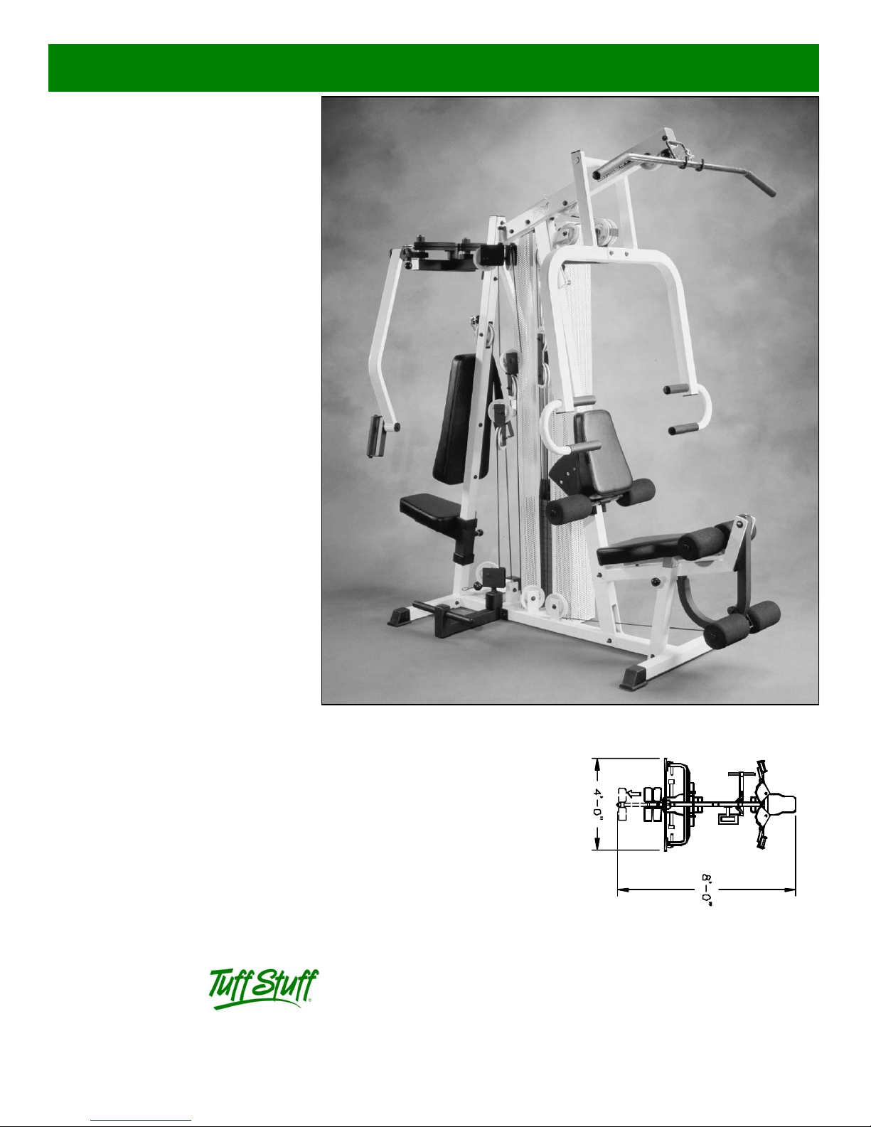
MSL-IV
Muscle IV Home Gym
America’s Premium Exercise Equipment
Revision Date 9 -98
L 8’-0” W 4’-0” H 7’-0”
Page 2
y
Introd
uction
bout the Muscle IV Home Gym (MSL-IV).
Congratulations on your new purchase of the Muscle IV
ome Gym (MSL-IV). This gym is capable of a variet y of
ifferent exercises, as well as, smooth and user-friendly
djustment features. In addition, this gym has been
esigned to meet the needs and performance requirements
r a suitable home exercise machine. We hope you are
ompletely satisfied with this product and wish you many
ears of enjoyment.
uff Stuff Equipment
Every Tuffstuff product has been built to precise quality
tandards and has been carefully packaged to ensure that
amage will not occur during shipment. The limited lifetime
arranty and signature indicating final inspection which was
onducted by our line foreman, is an expression of our
onfidence in the completeness, the materials, and
orkmanship of this product.
arranty
SEE WARRANTY REGISTRATION CARD
egistration Card
To avoid unnecessary delays in warranty parts and to
sure that a permanent record of your purchase is on file
ith our factory, be sure to complete the warranty
gistration card and send it to Task Industries today.
afety Information
) Familiarize yourself and others with the proper operation
nd workout recommendations for each piece of Tuff Stuff
quipment prior to use.
) Consult with your physician before beginning any
xercise program.
) Use proper discretion when children are present.
) Frayed or worn cables can be dangerous and may cause
jury. Periodically check these cables for any indication of
ear.
) Inspect machine for any sign of parts or hardware
ecoming loose.
Maintenance Information
1) Lubrication of all moving parts is essential to the longevit
and optimal performance of your Muscle IV Home Gym.
Initial lubrication of some parts of your gym have been done
at the factory, but the weight stack guide rods must be
lubricated at the time of assembly. We recommend a clear
aerosol, silicone or Teflon spray.
Note: Do not use oil based lubricants as they will attract
dust,dirt, and grime and will eventually gum up and erode
bushings and sealed bearings.
2) All pulleys and bushings should be checked regularly for
signs of wear.
3) Check and adjust tension on cables periodically as it will
maintain proper anatomical function.
4) Periodically check all moving parts, upholstery and grips
for wear. If replacement is necessary, please contact your
local Tuff Stuff retailer or call our Customer Service
Department.
5) As needed, upholstery may be cleaned with a mild
solution of soap and water. Regular use of a vinyl treatment
will add to the life and appearance of your upholstery.
6) All chrome plated surfaces should be cleaned regularly to
prolong the life and luster of the finish. Wipe machine down
with a damp cloth and dry thoroughly each day. At least
once a week your chrome equipment should be polished
with a commercial grade or automotive type chrome polish.
Tool Requirements
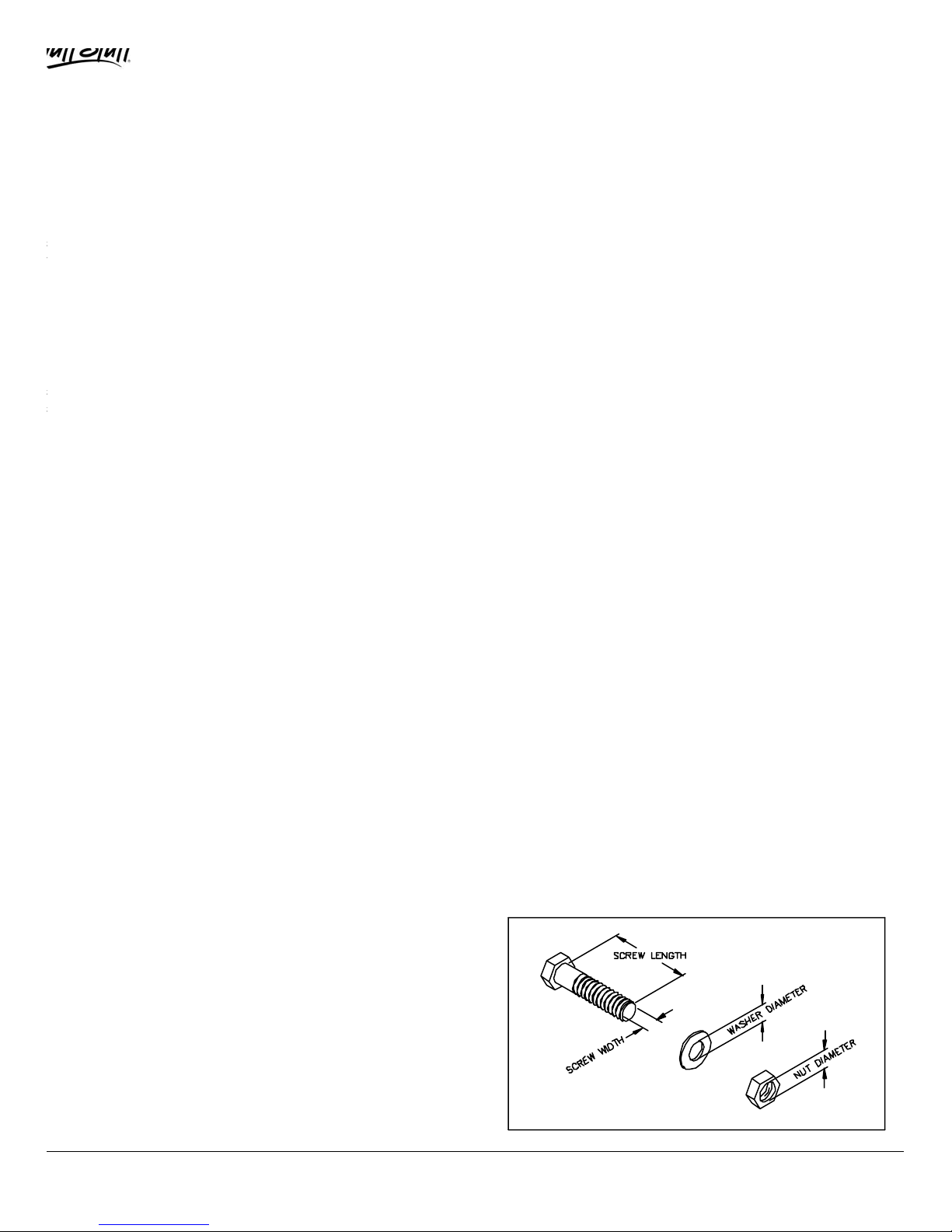
1) Two 3/4” Open-end wrenches
2) Two 9/16” Open-end wrenches
3) One rubber mallet
4) Needle nose pliers
5) One can Silicone Spray/ Teflon Spray Lubricant
6) Snap ring pliers
7) Hex Key 3/16” (Supplied)
7) Windex or household glass cleaner
Hardware Measurement Diagram
) Keep hands and limbs clear from weight stack and all
ther moving parts.
1
MSL-IV Muscle IV Home Gym
Page 3
e
y
c
t
Owners’ Manual: Assembly Instruction
s
IMPROVED
See #63 on page 19
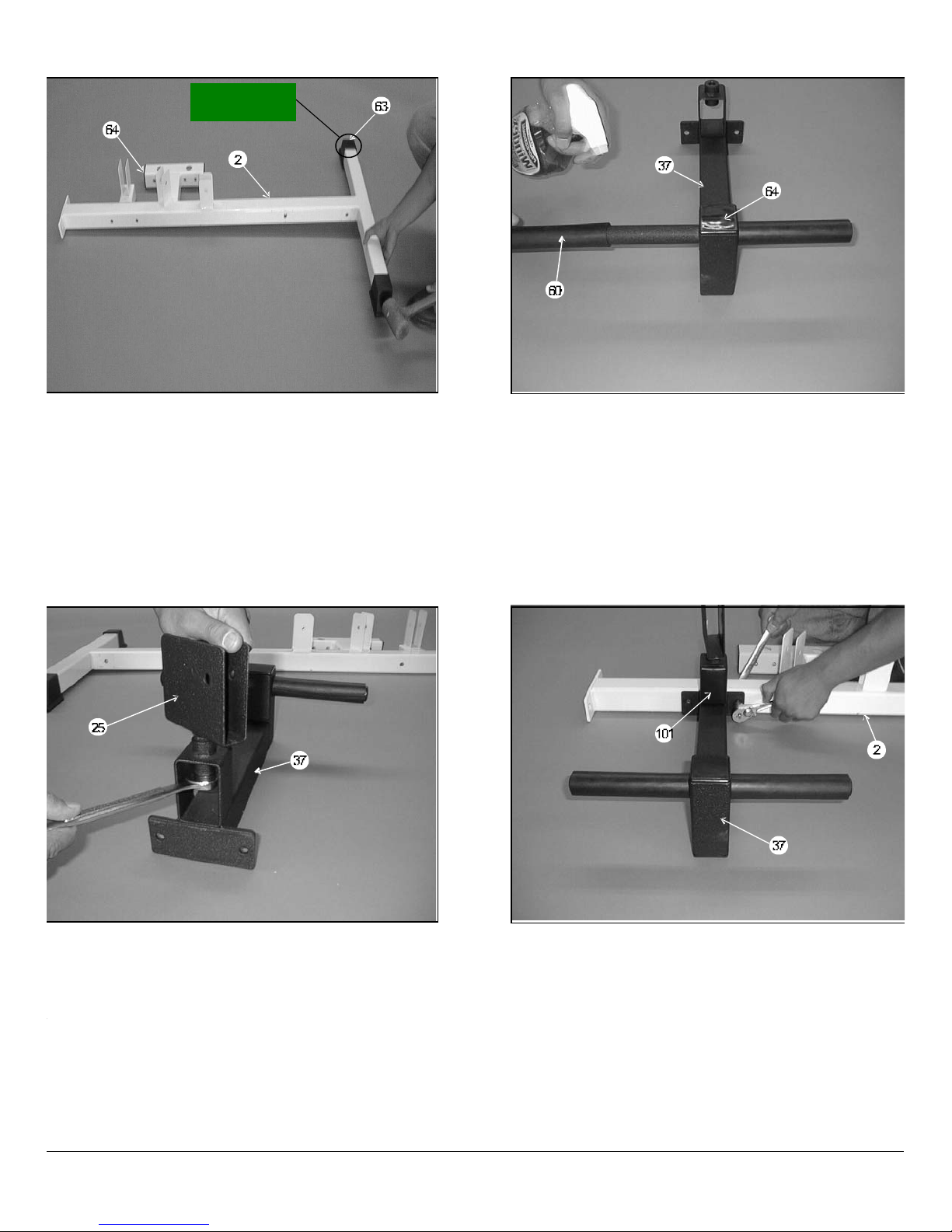
IG. 1 On a flat surface, lay the Base Frame (#2) down
nd insert two Plastic Insert Caps 2” Sq. (#64). Next, insert two
lastic Insert Caps 2” Sq. w/groove (#63) onto the front
tabilizer of the Base Fr ame (#2), as shown above.
FIG. 2 Locate the Low Row Foot Support (#37) and slid
a Hard Grip .875 X 8 (#60) over each end of the tube, as
illustrated above. The hard Grip .875 X 8 (#60) fits very tightl
onto the Low Row Foot Support (#37) and it may be
necessary to use windex or a household glass cleaner (as
shown) to complete this procedure. Next, insert one Plasti
Insert Cap 2” Sq. (#64) into the tube-end of the Low Row Foo
Support (#37).
IG. 3 Install the Low Row Swivel Pulley Bracket (#25)
nto the receptacle on the Low Row Foot Support (#37) and
ecure it using one Nylon Insert Jam Lock Nut 1/2-13 (#88)
nd one Flat Washer SAE 1/2 (#89). Note: It is recommended
hat the axle on the Low Row Swivel Pulley Bracket (#25)be
ubricated with grease prior to this assembly.
SL-IV Muscle IV Home Gym
FIG. 4 Attach the Low Row Foot Support (#37) to the
Base Frame (#2) and secure it using using two Hex Head Cap
Screws 3/8-16 X 2 3/4 (#77), four Flat Washers SAE 3/8 (#90)
and two Nylon Insert Jam Lock Nuts 3/8-16 (#86). Next, insert
two Plastic Insert Caps 2 X 3 (#101) into the pulley bracket
housing on the Low Row Foot Support (#37).
2
Page 4
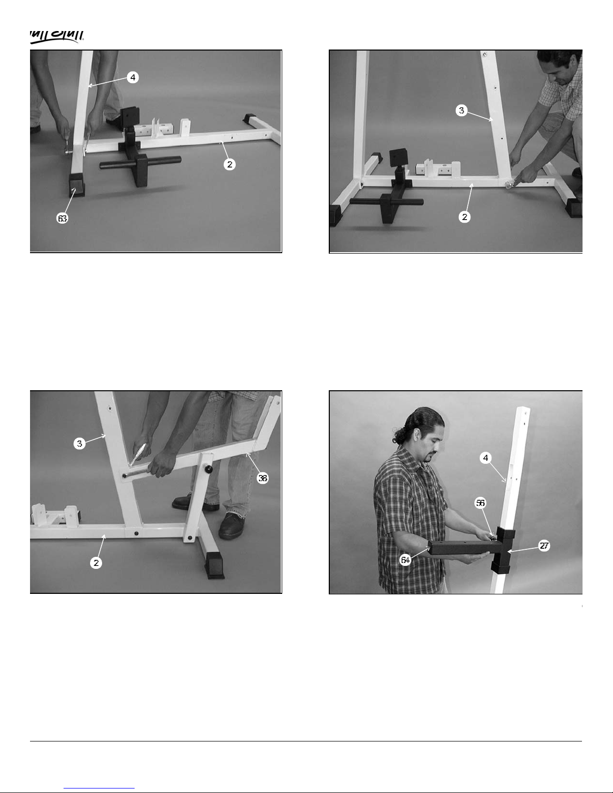
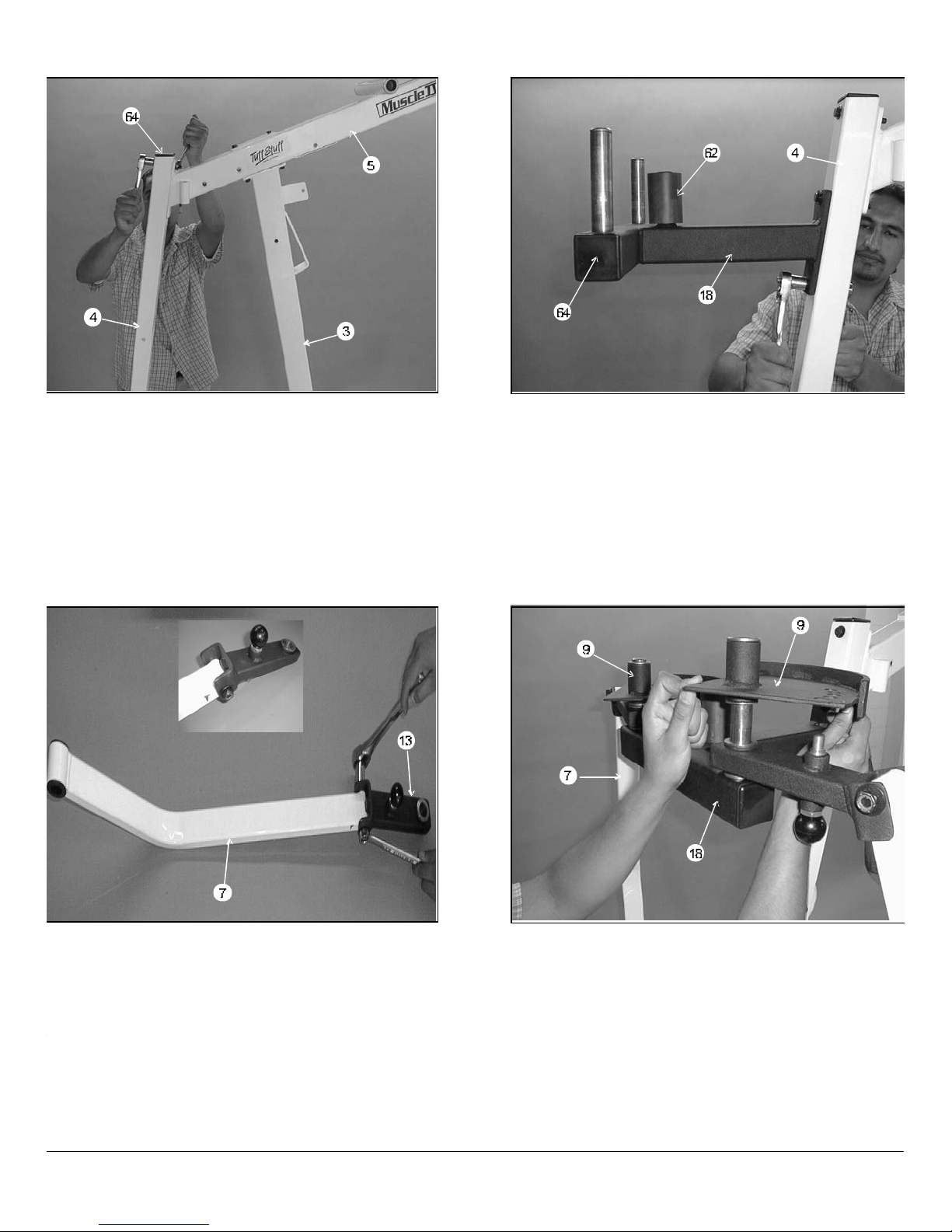
IG. 5 Attach the Rear Upright (#4) to the Base Frame (#2)
e
)
h
nd secure it using two Hex Head Cap Screws 3/8-16 X 2 3/4
#77), four Flat Washers SAE 3/8 (#90) and two Nylon Insert
ock Nuts 3/8-16 (#86). Note: Do not tighten this hardware
ssembly at this time. Next, insert two Plastic End Caps 2” Sq.
/groove (#63) into the Rear Upright (#4), as shown above.
FIG. 6 Attach the Front Upright (#3) to the Base Frame
(#2) and secure it using one Hex Head Cap Screw 3/8-16 X 2
3/4 (#77), two Flat Washers SAE 3/8 (#90) and one Nylon
Insert Jam Lock Nut 3/8-16 (#86). Note: Do not tighten this
hardware assembly at this time.
IG. 7 Attach the Leg Extension Seat Frame (#38) to the
ase Frame (#2). Secure the Leg Extension Seat Frame
#38) to the Base Frame (#2) using one Hex Head Cap Screw
/8-16 X 4 1/2 (#93), two Flat Washers SAE 3/8 (#90) and one
ylon Insert Jam Lock Nut 3/8-16 (#86). Next, secure the Leg
xtension Seat Frame (#38) to the Front Upright (#3) using
ne Hex Head Cap Screw 3/8 -16 X 2 3/4 (#77), two Flat
ashers SAE (#90) and one Nylon Insert Jam Lock Nut 3/8-16
#86). Note: Do not tighten this hardware assembly at this
ime.
3
FIG. 8 Slide the Pec Dec Adj Seat Tube (#27) onto th
Rear Upright (#4),as shown above. Note: Position the Pe
Dec Adj Seat Tube (#27) with the Push-Pull Pin 1/2 (#56
facing the same side as the selector holes on the Rear Uprig
(#4).
MSL-IV Muscle IV Home Gym
Page 5
:
6
e
Owners’ Manual: Assembly Instructions
IG. 9 Secure the Top Pulley Assembly (#5) to the Front
pright (#3) using two Hex Head Cap Screws 3/8-16 X 4 1/4
#99) four Flat Washers SAE 3/8 (#90) and two Nylon Insert
ock Nuts 3/8-16 (#86). Next, secure the Top Pulley
ssembly (#5) onto the Rear Upright (#4) using one Hex
ead Cap Screw 3/8-16 X 3 (#94), two Flat Washers SAE 3/8
#90) and one Nylon Insert Jam Lock Nut 3/8-16 (#86). Note:
his bolt should be placed in the top hole of the Rear Upright
#4).
FIG. 10 Next, attach the Pec Dec Housing (#18) to the
Rear Upright (#4). secure this assembly using one Hex Head
Cap Screw 3/8-16 X 3 1/2 (#8), two Flat Washers SAE 3/8
(#90) and one Nylon Insert Jam Lock Nut 3/8-16 (#86). Note
This bolt should be placed in the top hole of the Pec Dec
Housing (#18). Next, install one Hex Head Cap Screw 3/8 -1
X 3 (#94), two Flat Washers SAE 3/8 (#90) and one Nylon
Insert Jam Lock Nut 3/8-16 (#86) through the lower hole of th
Pec Dec Housing (#18). Finally, install the Rubber Stopper
(#62) and two Plastic Insert Caps 2 Sq. (#64), as shown
above.
IG. 11 Attach the Pec Dec Arm (#7) to the Pec Dec Arm/
am Support (#13) and secure it using one Hex Head Cap
crew 1/2-13 X 3 (#98), two Flat Washers SAE 1/2 (#89) and
ne Nylon Insert Jam Lock Nut 1/2-13 (#88). Repeat this
rocedure for the opposite Pec Dec Arm Assembly. Note: It is
ecommended that the axle on the Pec Dec Arm (#7) be
ubricated with grease prior to assembly.
SL-IV Muscle IV Home Gym
FIG. 12 Mount the assembled Pec Dec Arms (#7) in
Fig.11 to the Pec Dec Housing (#18) axles, as illustrated.
Note: It is recommended that the Pec Dec Housing (#18)
axles be lubricated with grease prior to assembly. Next, mount
the two Pec Dec Cams (#9) onto the the axles of the Pec Dec
Housing (#18), as shown above.
4
Page 6
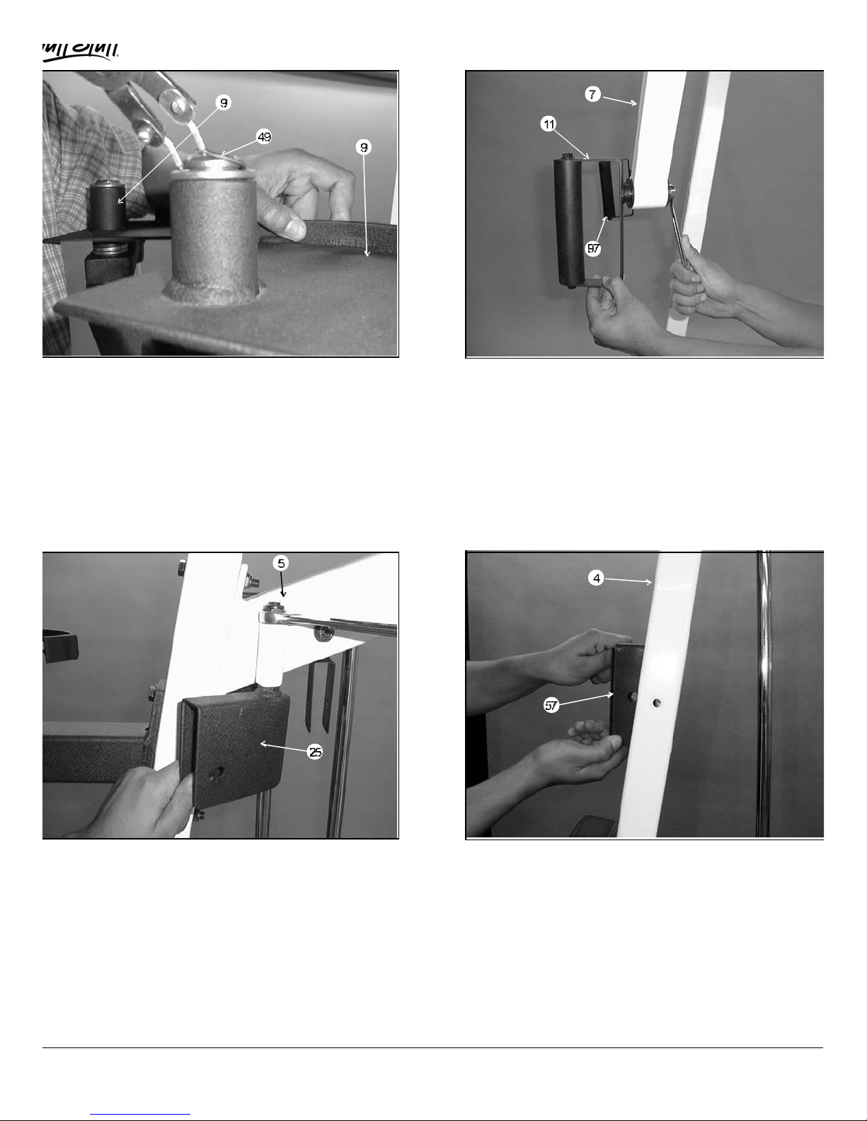
IG. 13 Secure the two Pec Dec Cams (#9) to the Pec
p
ec Housing (#18) using two Retaining Snap Rings (#49).If
ossible, use special snap ring pliers for this job, as shown
bove. If not available, carefully work each Retaining Snap
ing (#49) into the groove, then push down alternately with a
crew driver working the Retaining Snap Ring (#49) into the
roove. Note: Be careful not to distort the Retaining Snap
ing (#49) or bend it.
FIG. 14 Insert a Handle Bracket Left (#11) and Right
(#97) into the two Pec Dec Arms (#7) and secure them using
two Hex Head Cap Screws 3/8 -16 X 1 (#81) and two Fender
Washers 3/8- 1 1/2 (#106).
IG. 15 Insert the two Pec Dec Swivel Pulley Brackets
#25) into the receptacles on the Top Pulley Assembly (#5)
nd secure using four Flat Washers SAE 1/2 (#89) and two
ylon Insert Lock Nuts 1/2-13 (#88). Do not over-tighten these
uts, as the Pec Dec Swivel Pulley Brackets (#25) must
ove freely during use of the machine. Note: It is
ecommended that the Pec Dec Swivel Pulley Brackets (#25)
e greased prior to assembly.
5
FIG. 16 Install the Ab Crunch Insert Bracket (#57) and
one Nylon Pulley 4 1/2 Rd. (#35-Not shown See Fig 56) into
the Rear Upright (#4) and secure it using one Hex Head Ca
Screw 3/8-16 X 2 1/2 (#78), two Flat Washers SAE 3/8 (#90)
and one Nylon Insert Jam Lock Nut 3/8-16 (#86).
MSL-IV Muscle IV Home Gym
Page 7
o
Owners’ Manual: Assembly Instruction
s
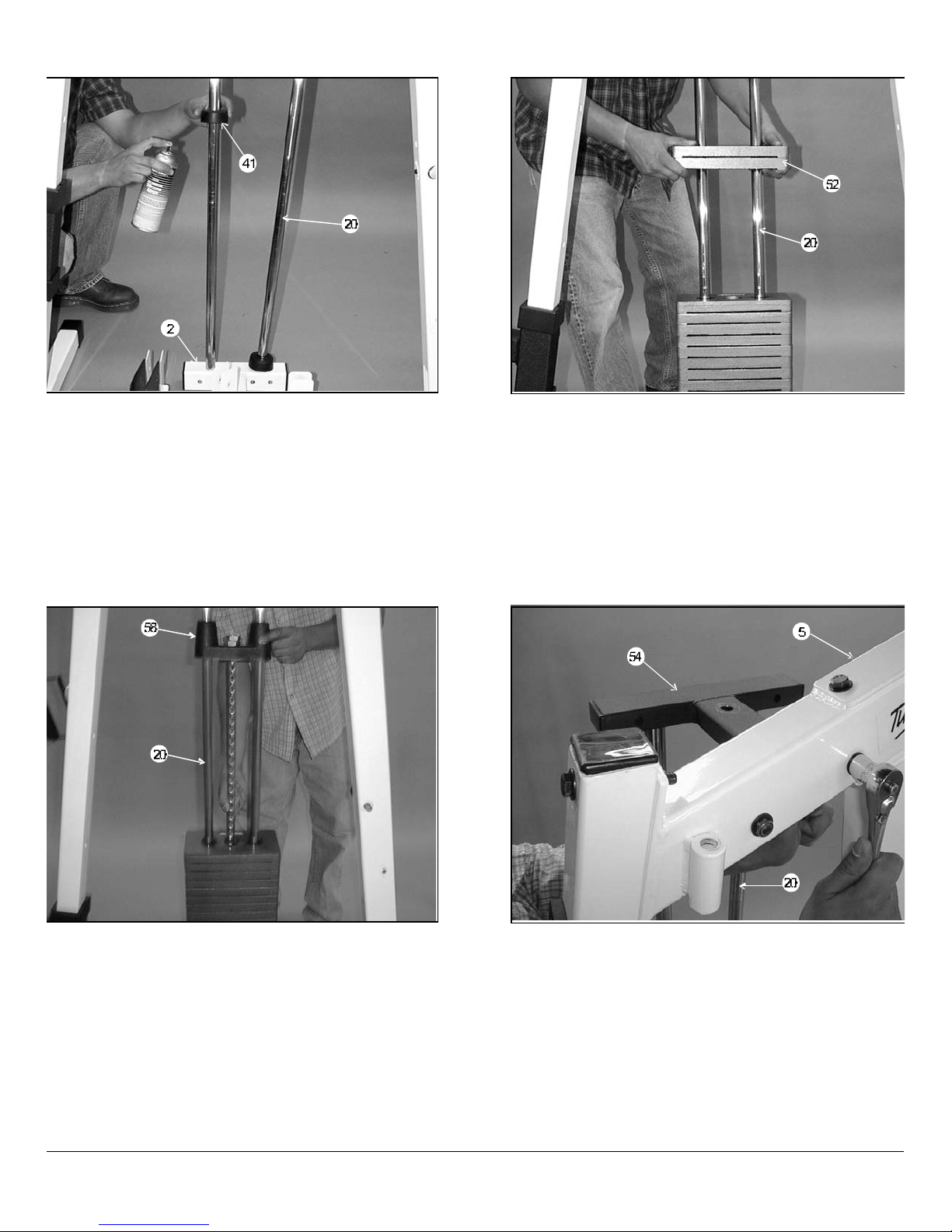
IG. 17 Insert the two Guide Rods (#20) into the
eceptacle of the Base Frame (#2), as shown above. Next,
nsert two Rubber Donuts 1 X 2 1/2 (#41) onto each each
uide Rod (#20). Note: Lubricate the Guide Rods (#20) with
ilicone or teflon lubricant at this time.
FIG. 18 Carefully begin sliding the 10 Lb. Weight Plates
(#52) over the Guide Rods (#20),one or two at a time as our
skill permits. Make sure that the 10 Lb. Weight Plates (#52)
are installed onto the Guide Rods (#20) in numerical order,
beginning with the number 200 at the bottom,190 next, and s
on.
IG. 19 Now slide the Top Plate/Selector Bar (#58) over
he Guide Rods (#20) allowing it to come to rest on the
ompleted weight stack.
SL-IV Muscle IV Home Gym
FIG. 20 Maneuver each of the Guide Rods (#20) into the
holes on the bottom side of the Guide Rod Retainer (#54).
Next, mount the Guide Rod Retainer (#54) along with the two
captive Guide Rods (#20) to the side of the Top Pulley
Assembly (#5). Secure this assembly using two Hex Head
Cap Screws 3/8 -16 X 3 (#94), four Flat Washers SAE 3/8
(#90) and two Nylon Insert Jam Lock Nuts 3/8-16 (#86).
6
Page 8
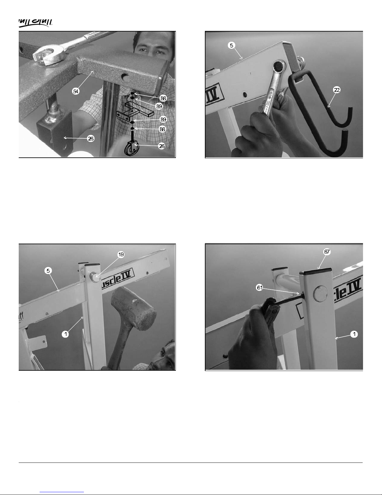
IG. 21 Locate the Adjustable Pulley Bracket (#26) and
r
hread a Hex Nut 1/2 -13 (#88) and a Flat Washer SAE 1/2
#89) onto it. Use the illustration above for further clarification
f this bolt and nut assembly. Next, insert the Adjustable
ulley Bracket (#26) into the Guide Rod Retainer (#54) and
ecure it using one Nylon Insert Jam Lock Nut 1/2-13 (#88)
nd one Flat Washer SAE 1/2 (#89). Note: Loosely secure the
ut to allow adjustment for cable tension later in the assembly
rocess.
FIG. 22 Insert the Lat Bar Holder (#22) into the tube-end of
the Top Pulley Assembly (#5), as shown above. Secure this
assembly using one Hex Head Cap Screw 3/8-16 X 2 1/2
(#78), two Flat Washers SAE 3/8 (#90) and one Nylon Insert
Jam Lock Nut 3/8-16 (#86).
IG. 23 Now position the Press Arm (#1) to the Top Pulley
ssembly (#5), as shown above. Next, press the Pivot Axle 1
11 3/4 (#19) through the holes in the Press Arm (#1) using
rubber mallet hammer until it is flush with both sides. Note:It
s recommened that the Pivot Axle 1 X 11 3/4 (#19) be
reased prior to this assembly.
7
FIG. 24 At the top of each end of the Press Arm (#1) is a
set screw fixture. Secure the Press Arm (#1) using two Set
Screws 3/8-16 X 1/2 (#61). Use the Hex Key 3/16 (#50) tool fo
securing the Set Screws 3/8-16 X 1/2 (#61). Next, insert two
Plastic Insert Caps 1 X 2 (#67) into the tube-ends of the Press
Arm (#1).
MSL-IV Muscle IV Home Gym
Page 9

Next, locate the Black Caster 2 X 1 (#34) and two
4
t
r
e
o
Owners’ Manual: Assembly Instruction
s
IG. 25 Locate the Range Of Motion Device (#48), the
arge Cable Retainer (#107) and two Nylon Pulleys 4 1/2 Rd.
#35). Assemble as shown using one Hex Head Cap Screw
/8-16 X 3 (#94), three Nylon Spacers 3/8 X 3/8 (#72), two Flat
ashers SAE 3/8 (#90) and one Nylon Insert Jam Lock Nut
/81-6 (#86). Refer to Fig. C on page 18 for further clarification
f this assembly.
FIG. 26
Nylon Spacers (#72). Assemble to the Range Of Motion
Device (#48) using one Hex Head Cap Screw 3/8-16 X 2 3/
(#77), two Flat Washers SAE 3/8 (#90) and one Nylon Inser
Jam Lock Nut 3/8-16 (#86). Refer to Fig. Con page 18 fo
further clarification of this assembly.
IG. 27 Locate the Range Of Motion Tube (#47) and one
houlder Bolt 3/8 X 3/8 (#95). Insert the Range Of Motion
ube (#47) into the Range Of Motion Device (#48), as shown
bove. Secure this assembly using the Hex Key 3/16 (#50).
SL-IV Muscle IV Home Gym
FIG. 28 Attach the Range Of Motion Tube (#47) onto th
Press Bar (#1) and secure it using two Hex Head Cap Screws
3/8-16 X 3 1/4 (#76), four Flat Washers SAE 3/8 (#90) and tw
Nylon Insert Jam Lock Nuts 3/8-16 (#87).
8
Page 10

IG. 29 Attach the Foot Roll Bracket (#46) to the Leg
t
d
g
e
xtension Arm (#42) and secure it using one Hex Head Cap
crew 1/2-13 X 2 3/4 (#92), two Flat Washers SAE 1/2 (#89)
nd one Nylon Insert Jam Lock Nut 1/2-13 (#88). Next, install a
ubber Bumper 3/8 X 1 1/2 (#33) to the Leg Extension Arm
#42), as shown above, and secure it using one Hex Head Cap
crew 3/8-16 X 1 (#81) and one Flat Washer SAE 3/8 (#90).
FIG. 30 Attach the Leg Extension Arm (#42) to the Leg
Extension Seat Frame (#38), as shown above, and secure it
using one Hex Head Cap Screw 1/2-13 X 3 1/4 (#96), two Fla
Washers SAE 1/2 (#89) and one Nylon Insert Jam Lock Nut
1/2-13 (#88). Note: Be sure not to over-tighten this hardware
assembly as the Leg Extension Arm (#42) should be allowe
to swivel freely. Also, it is recommended that the Le
Extension Arm (#42) be greased at the pivot point prior to
assembly.
IG. 31 Insert the Foot Roll Tube 1 X 16 (#100) through
he Foot Roll Bracket (#46). Then slide a Foam Foot Roll 7
4 X 1 (#32) onto each end of the Foot Roll Tube 1 X 16
#100). Next, insert a Plastic Insert Cap 1” Rd. (#65) into each
nd of the Foot Roll Tube 1 X 16 (#100).
9
FIG. 32 Attach the Seat Pad (Bench Press) (#45) to th
Bench Press Adj Seat Tube (#39) and secure it using two
Hex Head Cap Screws 3/8-16 X 1 3/4 (#79) and two Flat
Washers SAE 3/8 (#90), as shown above.
MSL-IV Muscle IV Home Gym
Page 11

IG. 33 Insert the Bench Press Adj Seat Tube (#39) into
s
4
6
he receptacle on the Leg Extension Bench Frame (#38),as
hown above. Next, insert two Foam Foot Rolls 7 X 4 X 1
#32) and two Plastic Insert Caps 1” Rd. (#65) onto the tube-
nds of the Foot Roll Tube 1 X 16 (#100). Note: Pull the
ush-pull pin 1/2 (#56) to allow the Bench Press Adj Seat
ube (#39) to adjust up and down.
FIG. 34 On the Bench Press Adj Seat Tube (#39) there i
a threaded socket. Secure the Foot Roll Tube 1 X 16 (#100)
using one Set Screw 1/4-20 X 1/4 (#105). Use the supplied
Hex Key 1/8 (#69) tool for securing this Set Screw (#114).
IG. 35 Mount the Back Pad Adj Bracket (#10) to the
ench Press Back Pad (#44) and secure using two Hex Head
ap Screws 3/8-16 X 1 (#81), two Bumper Washers 3/8 (#108)
nd two Bumper Caps Black (#91). Refer to the Exploded View
n page 19 for further clarification of this assembly.
SL-IV Muscle IV Home Gym
FIG. 36 Secure the Back Pad Bracket (#10) to the Front
Upright (#3) using one Hex Head Cap Screw 3/8-16 X 3 1/
(#76), four Flat Washers Nylon 3/8 (#6), two Flat Washers
SAE 3/8 (#90) and one Nylon Insert Jam Lock Nut 3/8-1
(#86). Refer to the Exploded View on page 19 for further
clarification of this assembly.
10
Page 12

IG. 37 Next, slide the Foot Roll Tube 1 X 23 3/4 (#55)
c
hrough the receptacles on the Back Pad Adj Bracket (#10),
s shown above. Next, install the Foam Foot Rolls 7 X 4 X 1
#32) as described in Fig. 31 on page 9.
FIG. 38 Attach the Pec Dec Seat Pad (#24) to the Pec De
Seat Adj Tube (#27) and secure it using two Hex Head Cap
Screws 3/8-16 X 2 3/4 (#77) and two Flat Washers SAE 3/8
(#90).
FIG. 39 Attach the Pec Dec Back Pad (#43)to
the Rear Upright (#4) and secure it using two Hex
Head Cap Screws 3/8-16 X 2 3/4 (#77) and two
Flat Washers SAE 3/8 (#90).
11
FIG. 40 Route the Lat Cable (#14) through the Top Pulley
Assembly (#5). Then insert one Nylon Pulley 4 1/2 Rd. (#35)
and secure it using one Hex Head Screw 3/8-16 X 2 1/2 (#78),
two Flat Washers SAE 3/8 (#90) and one Nylon Insert Jam
Lock Nut 3/8-16 (#86). Refer to Fig. 1 on page 17 for further
detailed illustration of this cable routing.
MSL-IV Muscle IV Home Gym
Page 13

Owners’ Manual: Assembly Instruction
s
IG. 41 Insert the Lat Cable (#14) and one Nylon Pulley 4
/2 Rd (#35) into the Top Pulley Assembly (#5) and secure it
sing one Hex Head Cap Screw 3/8-16 X 2 1/2 (#78), two Flat
ashers SAE 3/8 (#90) and one Nylon Insert Jam Lock Nut
/8-16 (#86). Refer to Fig. 1 on page 17 and Fig. B on page
8 for further detailed illustration of this cable routing.
FIG. 42 Route the Lat Cable (#14) over, then under the
Nylon Pulley 4 1/2 Rd. (#35), as illustrated above. Refer to Fig.
1 on page 17 and Fig. B on page 18 for further detailed
illustration of this cable routing.
IG. 43 Next, attach a Nylon Pulley 4 1/2 Rd. (#35) to the
ulley bracket on the Front Upright (#3) and secure it using
ne Hex Head Cap Screw 3/8 -16 X 1 3/4 (#79), two Flat
ashers SAE 3/8 (#90), one Nylon Insert Jam Lock Nut 3/8-16
#86) and one Cable Retainer Bracket (#111). Next, route the
at Cable (#14) under, then over the Nylon Pulley 4 1/2 Rd.
#35), as shown above. Refer to Fig. 1 on page 17 and Fig. B
n page 18 for further detailed illustration of this cable routing.
SL-IV Muscle IV Home Gym
FIG. 44 Continue to route the Lat Cable (#14) over the
Nylon Pulley 4 1/2 Rd. (#35), then under, as shown above.
Refer to Fig. 1 on page 17 and Fig. B on page 18 for further
detailed illustration of this cable routing.
12
Page 14

IG. 45 Attach a Nylon Pulley 4 1/2 Rd. (#35) to the
9
9
n
ront Upright (#3) and secure it using one Hex Head Cap
crew 3/8-16 X 3 3/4 (#75), two Flat Washers SAE 3/8 (#90),
ne Nylon Insert Jam Lock Nut 3/8-16 (#86) and one Cable
etainer Bracket (#111). Then continue to route the Lat
able (#14) over the pulley as shown. Refer to Fig. 1 on page
7 and Fig. B on page 18 for further detailed illustration of this
able routing.
FIG. 46 Assemble the Double PulleyPlates 1/8 X 2 X
(#21) using two Nylon Pulleys 4 1/2 Rd. (#35), two Hex Head
Cap Screw 3/8-16 X 1 3/4 (#79), four Flat Washers SAE 3/8
(#90) and two Nylon Insert Jam Lock Nuts 3/8-16 (#86). Refer
to Fig. 1 on page 17 for further detailed illustration of this
cable routing. Next, route the Lat Cable (#14) through the
Double Pulley Plates 1/8 X 2 X 9 (#21), as shown above.
Note: The four holes on the Double Pulley Plates 1/8 X 2 X
(#21) are used to adjust the cable tension once the cable
routing has been completed.
IG. 47 Insert a Nylon Pulley 4 1/2 Rd. (#35) into the
djustable Pulley Bracket (#26) and secure it using one Hex
ead Cap Screw 3/8-16 X 1 3/4 (#79), two Flat Washers SAE
/8 (#90) and one Nylon Insert Jam Lock Nut 3/8-16 (#86).
oute the Lat Cable (#14) through the Adjustable Pulley
racket (#26), as shown above.
13
FIG. 48 Attach the Lat Cable (#14) to the Top Plate /Selecto
Bar (#58) and secure it using one Split Bolt 1/2-13 X 1 (#51) a
one Split Washer 1/2 (#82). Refer to Fig. E on page 18 for
further detailed illustration of this assembly. Note: Be sure this
hardware assembly is securely fastened.
MSL-IV Muscle IV Home Gym
Page 15

f
o
s
6
y
8
Owners’ Manual: Assembly Instruction
s
IG. 49 Begin routing the Pec Dec Cable (#16).Attach one
nd of the Pec Dec Cable (#16) to the Pec Dec Cam (#9) and
ecure it using one Socket Head Cap Screw 1/4 X 3/4 (#102)
nd one Nylon Insert Jam Lock Nut 1/4-20 (#103). Refer to
ig. A on page 18 for further detailed illustration of this
ssembly.
FIG. 50 Attach one Nylon Pulley 4 1/2 Rd. (#35) to each o
the Swivel Pulley Brackets (#25) and secure them using tw
Hex Head Cap Screws 3/8-16 X 1 3/4 (#79), four Flat Washer
SAE 3/8 (#90) and two Nylon Insert Jam Lock Nuts 3/8-1
(#86). Route the Pec Dec Cable (#16) over the Nylon Pulle
4 1/2 Rd. (#35), as shown above. Refer to Fig. Aon page 1
for further detailed illustration of this cable routing.
IG. 51 Insert two Nylon Pulleys 4 1/2 Rd. (#35) into the
ffset Pulley Bracket (#23) and secure them using two Hex
ead Cap Screws 3/8-16 X 1 3/4 (#79), four Flat Washers SAE
/8 (#90) and two Nylon Insert Jam Lock Nuts 3/8-16 (#86).
ext, route the Pec Dec Cable (#16) through this bracket, as
hown above. Repeat the same procedure in Fig. 49 and Fig.
0 to complete the routing of the Pec Dec Cable (#16). Refer to
ig. A on page 18 for further detailed illustration of this cable
outing.
SL-IV Muscle IV Home Gym
FIG. 52 Attach the Leg Extension Cable (#15) to the Leg
Extension Arm (#42) and secure it using one Hex Head Cap
Screw 3/8-16 X 1 (#81) and one Nylon Insert Jam Lock Nut
3/8-16 (#86). Refer to Fig. F on page 18 for further detailed
illustration of this cable routing.
14
Page 16

IG. 53 Insert a Nylon Pulley 4 1/2 Rd. (#35) into the pulley
e
e
s
racket on the Base Frame (#2) and secure it using one Hex
ead Cap Screw 3/8-16 X 1 3/4 (#79), two Flat Washers SAE
/8 (#90) and one Nylon Insert Jam Lock Nut 3/8-16 (#86).
ext, insert the Leg Extension Cable (#15) through the Front
pright (#3) then through the Nylon Pulley 4 1/2 Rd. (#35), as
hown above. Refer to Fig. I on page 17 for further detailed
llustration of this cable routing.
FIG. 54 Next, lift the loose end of the Leg Extension Cabl
(#15) up into the Double Pulley Plates 1/8 X 2 X 9 (#21),as
shown above. Refer to Fig. I on page 17 for further detailed
illustration of this cable routing.
IG. 55 Insert a Nylon Pulley 4 1/2 Rd. (#35) into the
ulley bracket on the Base Frame (#2) and secure it using one
ex Head Cap Screw 3/8 -16 X 1 3/4 (#79), two Flat Washers
AE 3/8 (#90) and one Nylon Insert Jam Lock Nut 3/8-16
#86). Next, route the Leg Extension Cable (#15) through the
ylon Pulley 4 1/2 Rd. (#35), as shown above.
15
FIG. 56 Now, lift the loose end of the Leg Extension Cabl
(#15) and route it through the Offset Pulley Bracket (#23),a
shown above.
MSL-IV Muscle IV Home Gym
Page 17

e
w
Owners’ Manual: Assembly Instructions
IG. 57 Next, route the Leg Extension Cable (#15) through
he Offset Pulley Bracket (#23), as shown above. Refer to
ig. I on page 17 for further detailed illustration of this cable
outing.
FIG. 58 Finally, route the remainder of the Leg Extension
Cable (#15) through the Nylon Pulley 4 1/2 Rd. (#35) located
on the Rear Upright (#4). Then, assemble the Strap Bracket
(#83) and the Abdominal Strap (#53) onto the cable-end of th
Leg Extension Cable (#15). Secure this assembly using one
Shoulder Bolt 3/8 X 3/4 (#80), one Nylon Ball 1 3/4 X 5/16
(#85) and one Nylon Insert Lock Nut 5/16-18 (#84). Refer to
Fig. D on page 18 for further detailed illustration of this
assembly.
IG. 59 Insert the end of the Low Row Cable (#17) into the
ow Row Swivel Pulley Bracket (#40) and secure it into
lace using one Nylon Pulley 4 1/2 Rd. (#35). Use the pulley
ounting hardware described in Fig. 55 on page 15 to fasten
he pulley and cable into place.
SL-IV Muscle IV Home Gym
FIG. 60 Insert a Nylon Pulley 4 1/2 Rd. (#35) and the Lo
Row Cable (#17), as shown above. Use the pulley mounting
hardware described in Fig. 55 on page 15 to fasten the pulley
into place.
16
Page 18

IG. 61 Finally, coonect the end of the Low Row Cable
#17) to the empty pulley bracket located on the Base Frame
#2) and secure it using one Hex Head Cap Screw 3/8 -16 X 1
/4 (#79), two Flat Washers SAE 3/8 (#90), two Nylon
pacers 3/8 X 3/8 (#72) and one Nylon Insert Jam Lock Nut
/8-16 (#86). Refer to Fig. Gon page 18 for further detailed
llustration of this assembly.
See Figure B
See Fig. B
Fig. I
FIG. 62 This completes the assembly of the MSL-IV. It is
recommended that you check and secure all the hardware
assemblies and inspect all cable routing for proper tension and
assembly.
See Figure A
See Figure D
See Figure C
See Figure G, H
See Figure D
Note:Some Parts
Not Shown or cut
away for clarity
See Figure E
See Figure F
17
See Figure G, H
MSL-IV Muscle IV Home Gym
Page 19

Owners’ Manual: Assembly Instructions
FIG. BFIG. A
Note: Some Parts Have Been Cut
Away For Clarity.
FIG. C FIG. D FIG. E
FIG. HFIG. GFIG. F
SL-IV Muscle IV Home Gym
Leg Press Configuration
18
Page 20

19
MSL-IV Muscle IV Home Gym
Page 21

o
o
y
2
0
6
8
4
COLOR CHART
GRAY= SUB-ASSEMBLY PARTS
BLACK= HARDWARE
m N
1 PRESS BAR MSL4-01-00 1 59 COIL CHAIN 3/16 X 21 BNH0017 1
2 BASE FRAME MSL4-02-00 1 60 HARD GRIP .875 X 8 BNH0523 6
3 FRONT UPRIGHT MSL4-03-00 1 61 SET SCREW 3/8-16 X 1/2 BNH0474 2
4 REAR UPRIGHT MSL4-04-00 1 62 RUBBER STOPPER 1 X 2 X 2 3/4 BNH0611 1
5 TOP PULLEY ASSEMBLY MSL4-05-00 1 63 PLASTIC END CAP 2" SQ W/GROOVE BNH0050 4
6 NYLON WASHER 3/8 USS BNH0248 4 64 PLASTIC INSERT CAP 2" SQ BNH0012 1
7 PEC DEC ARM MSL4-07-00 2 65 PLASTIC INSERT CAP 1" RD BNH0002 6
8 HEX HEAD CAP SCREW 3/8-16 X 3 1/2 BNH0280
9 PEC DEC CAM MSL4-08-00 2 67 PLASTIC INSERT CAP 1 X 2 BNH0005 7
10 BACK PAD ADJUSTMENT BRACKET UP179 1 68 PLASTIC INSERT CAP 1 1/4 RD BNH0573 4
11 PEC DEC HANDLE BRACKET (LEFT) MSL4-11-00 1 69 HEX KEY LONG 1/8" BNH0767 1
12 PEC DEC HOUSING MSL4-12-00 1 70 RUBBER HOSE 1 1/4 X 5 1/2 BNH0807 2
13 PEC DEC ARM/ CAM SUPPORT MSL4-13-00 2 71 RUBBER HOSE 1 1/4 X 7 BNH0807 4
14 LAT CABLE MSL4-14-00 1 72 NYLON SPACER 3/8 X 3/8 BNH0392 5
15 LEG EXTENSION CABLE MSL4-15-00 1 73 NYLON BUSHING 1 X 1 1/2 BNH0531 4
16 PEC DEC CABLE MSL4-16-00 1 74 BRONZE BUSHING 1 X 1 1/4 BNH0527 1
17 LOW ROW CABLE MSL4-17-00 1 75 HEX HEAD CAP SCREW 3/8-16 X 3 3/4 BNH0281 1
18 NYLON STEM BUTTON 5/16 BNH0533 2 76 HEX HEAD CAP SCREW 3/8-16 X 3 1/4 BNH0312 3
19 PIVOT AXLE 1 X 11 3/4 UP067 1 77 HEX HEAD CAP SCREW 3/8-16 X 2 3/4 BNH0278 11
20 GUIDE ROD 1 X 72 UP124 2 78 HEX HEAD CAP SCREW 3/8-016 X 2 1/2 BNH0276 4
21 DOUBLE PULLEY PLATE 1/8 X 2 X 9 UP092 2 79 HEX HEAD CAP SCREW 3/8-16 X 1 3/4 BNH0274 1
22 LAT BAR HOLDER 2 X 3 UP096 1 80 SHOULDER BOLT 3/8 X 3/4 BNH0718 2
23 OFFSET PULLEY BRACKET UP121 2 81 HEX HEAD CAP SCREW 3/8-16 X 1 BNH0275 6
24 PEC DEC SEAT PAD UP122 1 82 SPLIT WASHER 1/2" BNH0572 1
25 PEC DEC SWIVAL PULLEY BRACKET UP126 3 83 STRAP BRACKET #20 BNH0562 2
26 ADJ PULLEY BRACKET UP127 1 84 NYLON INSERT LOCK NUT 5/16-18 BNH0215 2
27 PEC DEC SEAT ADJ TUBE UP133 1 85 NYLON BALL 1 3/4 X 5/16 BNH0392 3
28 LAT BAR CHROME 48" UP093 1 86 NYLON INSERT JAM LOCK NUT 3/8-16 BNH0365 2
29 LOW ROW BAR 16" UP094 1 87 NYLON INSERT LOCK NUT 3/8-16 BNH0214 9
30 WEIGHT SELECTOR PIN BNH0064 1 88 NYLON INSERT JAM LOCK NUT 1/2-13 BNH0366 9
31 PLASTIC TUBE GUIDE 2 1/2 SQ BNH0060 2 89 FLAT WASHER SAE 1/2" BNH0238 7
32 FOAM FOOT ROLL 7 X 4 X 1 BNH0043 6 90 FLAT WASHER SAE 3/8" BNH0239 8
33 RUBBER BUMPER 3/8 X 1 1/2 BNH0514 1 91 BUMPER CAP BLACK BNH0412 2
34 BLACK CASTER 2 X 1 BNH0633 1 92 HEX HEAD CAP SCREW 1/2-13 X 2 3/4 BNH0261 1
35 NYLON PULLEY 4 1/2 RD BNH0556 1 9 93 HEX HEAD CAP SCREW 3/8-16 X 4 1/2 BNH0284 1
36 SNAP LINK ZINC BNH0065 3 94 HEX HEAD CAP SCREW 3/8-16 X 3 BNH0282 4
37 LOW ROW FOOT SUPPORT UP177 1 95 SHOULDER BOLT 3/8 X 3/8 BNH0422 1
38 LEG EXTENSION BENCH FRAME UP172 1 96 HEX HEAD CAP SCREW 1/2-13 X 3 1/4 BNH0576 1
39 BENCH PRESS ADJ SEAT TUBE UP171 1 97 HANDLE BRACKET (RIGHT) MSL4-97-00 1
40 PUSH-PULL PIN 1/2" (SPECIAL) BNH0516 3 98 HEX HEAD CAP SCREW 1/2-13 X 3 BNH0264 2
41 RUBBER DONUT BNH0062 2 99 HEX HEAD CAP SCREW 3/8-16 X 4 1/4 BNH0317 3
42 LEG EXTENSION ARM UP150 1 100 FOOT ROLL TUBE 1 X 16 UP053 2
43 PEC DEC BACK PAD UP147 1 101 PLASTIC INSERT CAP 2 X 3 BNH0052 1
44 BACK PAD (BENCH PRESS) MSL4-44-00 1 102 SOCKET HEAD CAP SCREW 1/4 X 3/4 BNH0452 2
45 SEAT PAD (BENCH PRESS) UP173 1 103 NYLON INSERT LOCK NUT 1/4-20 BNH0213 2
46 FOOT ROLL BRACKET UP176 1 104 HEX HEAD CAP SCREW 3/8-16 X 1 1/4 BNH0273 4
47 RANGE OF MOTION TUBE MSL4-47-00 1 105 SET SCREW 1/4-20 X 1/4 BNH0790 2
48 RANGE OF MOTION DEVICE MSL4-48-00 1 106 FENDER WASHER 3/8 X 1 1/2 BNH0195 6
49 RETAINING SNAP RING BNH0419 2 107 CABLE RETAINER BRACKET LARGE UP160 1
50 HEX KEY 3/16 BNH0371 1 108 BUMPER WASHER 3/8 BNH0498 2
51 SPLIT BOLT 1/2-13 X 1 BNH0479 1 109 PVC TUBE 1 X 7 BNH0417 2
52 10 LB WEIGHT PLATE GREY BNH0561 1 9 110 NYLON SPACER 3/8 X 7/8 X 3/4 BNH0726 1
53 ABDOMINAL STRAP BNH0821 1 111 CABLE RETAINER BRACKET UP014 2
54 GUIDE ROD RETAINER HOUSING UP169 1 112 VELCRO ANKLE STRAP 20000-VNAS 1
55 FOOT ROLL TUBE 1 X 23 3/4 UP180 1 113 AXLE TUBE 1 X 7 MSL4-113-00 2
56 PUSH-PULL PIN 1/2" BNH0515 3 114 TUBEING CONNECTOR 3/8-16 BNH0551 4
57 AB CRUNCH INSERT BRACKET UP119 1 115 BRONZE BUSHING 1/2 X 5/8 BNH0528 2
58 TOP PLATE/ SELECTOR BAR UP003 1 116 STAINLESS STEEL TAPE 1 X 8 BNH0740 1
MSL-IV PARTS LIST
Description Part No. Qtytem N
1 66 PLASTIC INSERT CAP 1 1/2 SQ BNH0009 1
Description Part No. Qt
SL-IV Muscle IV Home Gym
20
Page 22

Notes_____________________________________________________________
_
_
_
_
_
_
_
_
_
_
_
_
_
_
_
_
_
_________________________________________________________________
_________________________________________________________________
_________________________________________________________________
_________________________________________________________________
_________________________________________________________________
_________________________________________________________________
_________________________________________________________________
_________________________________________________________________
_________________________________________________________________
_________________________________________________________________
_________________________________________________________________
_________________________________________________________________
_________________________________________________________________
_________________________________________________________________
_________________________________________________________________
_________________________________________________________________
_________________________________________________________________
21
MSL-IV Muscle IV Home Gym
Page 23

Notes_____________________________________________________________
_
_
_
_
_
_
_
_
_
_
_
_
_
_
_
_
_
_________________________________________________________________
_________________________________________________________________
_________________________________________________________________
_________________________________________________________________
_________________________________________________________________
_________________________________________________________________
_________________________________________________________________
_________________________________________________________________
_________________________________________________________________
_________________________________________________________________
_________________________________________________________________
_________________________________________________________________
_________________________________________________________________
_________________________________________________________________
_________________________________________________________________
_________________________________________________________________
_________________________________________________________________
SL-IV Muscle IV Home Gym
22
Page 24

DO NOT DISCARD THIS MANUAL
1325 E. Franklin Ave., Pomona, CA 91766
Ph: 909-629-1600 Fax: 909-629-4967
E-mail: taskind@aol.com Net: www.tuffstuff.net
 Loading...