

Page 1
OWNER’ S MANUAL
TABLE OF CONTENTS:
Introduction - Pg. 1
Safety Precautions - Pg. 2
Assembly for CFM-550
Pg. 3 - Pg. 17
Cable Adjustments Diagram- Pg. 18
Cable Mapping Diagram - Pg. 20
Exploded View Diagram - Pg. 21
Parts List - Pg. 22
Adjustment Features
Pg. 23 - Pg. 24
Maintenance - Pg. 25
Warranty - Back Page
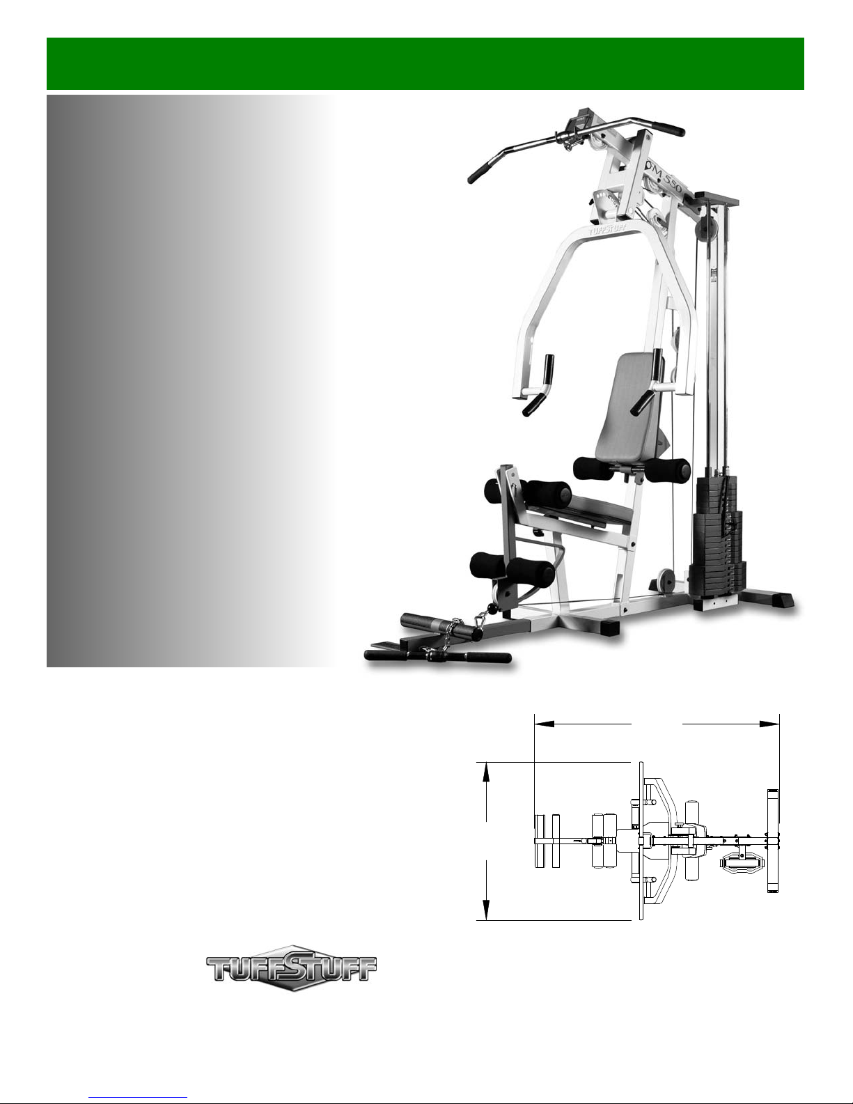
CFM-550
Compact Frontal Machine
America’s Premium Exercise Equipment
Revision Date 06-26-01
75”
48”
L 75” W 48” H 84”
© 2000 TASK INDUSTRIES, INC.
CFM-550 Rev. 0
Page 2
Introduction
About the Compact Frontal Machine (CFM-550)
Congratulations on your new purchase of the Compact Frontal
Machine (CFM-550). This gym is capable of a variety of different
exercises, as-well-as, smooth and user-friendly adjustment
features. In addition, this gym has been designed to meet the
needs and performance requirements for a suitable home exercise
machine. We hope you are completely satisfied with this product
and wish you many years of enjoyment.
Tuff Stuff Equipment
This Tuffstuff product has been built to precise quality standards
and has been carefully packaged to ensure that damage will not
occur during shipment.
indicating final inspection has been conducted by our line foreman,
is an expression of our confidence in the completeness, the
materials, and workmanship of this product.
The Home Lifetime Warranty and signature
Warranty
SEE A COPY OF WARRANTY ON BACK PAGE.
Registration Card
To avoid unnecessary delays in warranty service and to insure that
a permanent record of your purchase is on file with our factory, be
sure to complete the warranty registration card and send it to Task
Industries today.
Specifications
1. Maximum Wt. Capacity - 200 Lbs. Fixed
2. Total Machine Weight - 430 Lbs.
3. Footprint (LWH) - See Front Cover
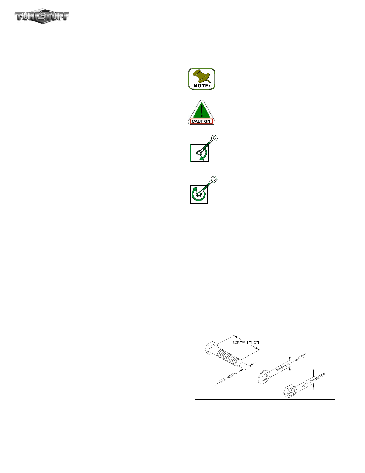
About the Icons
The icons displayed in this Owner’s Manual are used to facilitate
the correct assembly and safe use of this Product, as-well-as to
prevent injury to yourself or anyone else.
Note provides information necessary to properly
complete a procedure or information which will
make the procedure easier to understand.
Caution indicates a potentially hazardous situa-
LOOSELY FASTEN
FULLY FASTEN
tion, which, if not avoided, may result in minor or
moderate injury. It may also be used to alert
against unsafe practices.
Loosely Fasten provides a instruction to loosely
fasten (ex: hand tighten) a hardware assembly
only. This instruction is intended for the alignment
of hardware components during the assembly
process.
Fully Fasten provides a instruction to fully fasten
(ex: completely tighten) a hardware assembly.
Prior to the Assembly of the CFM-550
1. We advise you to consult your local Tuff Stuff retailer if you
should have a question or problem regarding the proper
assembly of this Compact Frontal Machine (CFM-550).
2. Consider the complete surface area of the CFM-550. Use the
overhead view located on the front page for designing your
layout before assembling. Once the CFM-550 has been fully
assembled it will be heavy and difficult to move, therefore you
should assemble the CFM-550 in the area where it is to be used
upon completion.
3. It is recommended that another person assist you with the
assembly of this unit.
4. Neatly organize and identify all parts according to the Parts List
on page 22, and the Exploded View Diagram on page 21.
Tool Requirements
1.One 9/16” combination wrench
2.One 3/4” combination wren ch
3.One 7/8” combination wrench
4.One 1/2” combination wrench
5.Two 7/16” combination wrenches
6.One ratchet
7.One 9/16” socket
8.One 3/4” socket
9.One rubber mallet
10.Windex or household glass cleaner
11.One can silicone spray/ teflon spray lubricant
12.Multi-purpose grease
13.Measuring tape
14.Utility knife
Assembly Notes
1. Read and follow each step of this Assembly Instruction Manual in
sequence. Do not skip ahead, as it will result in an improper
assembly or in having to disassemble parts later.
2. During the assembly of this unit you will be instructed to leave
some Hex Head Cap Screws loosely fastened. Naturally, they
will be fully fastened later in the assembly process. This is done
to prevent any difficulty with alignment of some parts during this
Hardware Measurement Diagram
Note: Due to continuing product improvements, specifications and designs are subject to change
without notice.
Even though we have prepared this manual with extreme care, neither the publisher nor the author
can accept responsibility for any errors in, or omission from, the information given.
1
CFM-550 Compact Frontal Machine
Page 3
Safety Precautions
S afety First
Regardless of how enthusiastic you may be about getting on
your equipment and exercising, take the time to ensure that
your safety is not jeopardized. A moment’s lack of attention
can result in an accident, as can failure to observe certain
simple safety precautions.
1. Read, study and understand the Owner’s Manual and all
the warning labels on this product. Furthermore, it is
recommended to familiarize yourself and others with the
proper operation and workout recommendations for this
Tuff Stuff product prior to use. Some of this information
can be obtained in this Owner’s Manual, as-well-as from
your local Tuff Stuff retailer.
2. It is imperative that you retain this Owner’s Manual and be
sure all warning labels are legible and intact.
Replacement Owner’s Manuals and labels are available
from your local Tuff Stuff retailer.
3. Consult with your physician before beginning any exercise
program.
4. Use proper discretion when children are present.
5. Frayed or worn cables can be dangerous and may cause
injury. Periodically check these cables for any indication
of wear.
6. Keep hands, limbs, loose clothing and long hair well out of
the way of moving parts.
7. Do not attempt to lift more weight than you can control
safely.
8. Inspect the Compact Frontal Machine for any sign of wear
on parts, hardware becoming loose or cracks on welds. If
a problem is found do not use or allow the machine to
be used until the defective part is repaired or replaced.
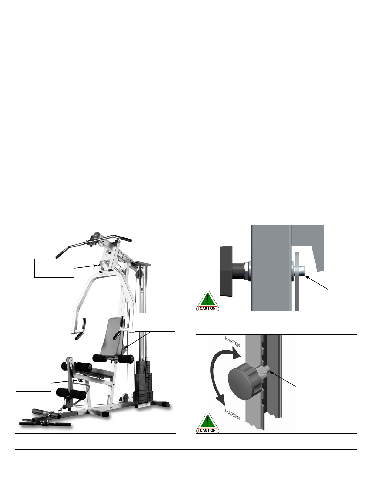
9. Pay special attention to the Push Pull Pins 1/2 X 3-1/2
(#38) located on the Press Bar Selector Housing (#7),
and the Front Upright (#5), also the Turn/Pull Pin w/
Knob (#39) located on the Leg Extension Bench Frame
(#4). See Fig.1. Be sure they are fully engaged into the
selected holes. Refer to Fig. 2, 3 for further illustration of
this instruction.
Push Pull Pin
1/2 X 3-1/2 (#38)
Push Pull Pin
1/2 X 3-1/2 (#38)
Turn/Pull Pin
w/Knob (#39)
Fig. 1 Illustration above depicts the location of the Push Pull Pins 1/2”
X 3-1/2 (#38) and the Turn/Pull Pin w/Knob (#39) on this unit.
Push Pull Pin
1/2 X 3-1/2
Fully Engaged
Fig. 2 Caution: Check that the two Push Pull Pins 1/2 X 3-1/2 (#38)
located on the Press Bar Selector Housing (#7), and the Front Upright
(#5) are fully engaged into the selected holes of the Press Bar (#6), and
the Back Pad Bracket (#12).
Turn/Pull Pin w/Knob
Fully Engaged
Fig. 3 Caution: Check the Turn/Pull Pin w/Knob (#39) to be fully
engaged into the selected hole of the Bench Press Adj. Seat Tube (#9).
CFM-550 Compact Frontal Machine
2
Page 4

FIG. 4 On a flat surface, lay the Base Frame (#1) down and insert four
Plastic End Caps w/Groove 2” Sq. (#47) onto the tube-ends of the Base
Frame (#), as shown above.
Note: When positioning the Base Frame (#1) consider the
complete area surface of the CFM-550. Use the overhead view on
the cover page for designing your layout before assembling.
FIG. 5 Next, locate the Low Row Foot Assembly (#10) and, using a
rubber mallet, insert two Plastic End Caps 2” Rd. (#56) and one Plastic
Insert Cap 1-3/4 Sq. (#57) into the tube-ends. Next, slide the Low Row
Foot Assembly (#10) into the receptacle of the Base Frame (#1), as
shown above.
FIG. 6 Next, locate the Rear Upright (#2) and, using a rubber mallet,
insert one Plastic Insert Cap 2 X 3 (#54) into the tube-end. Next, insert
two Plastic End Caps w/Groove 2 X 3 (#48) onto the stabilizer of the Rear
Upright (#2), as shown above.
3
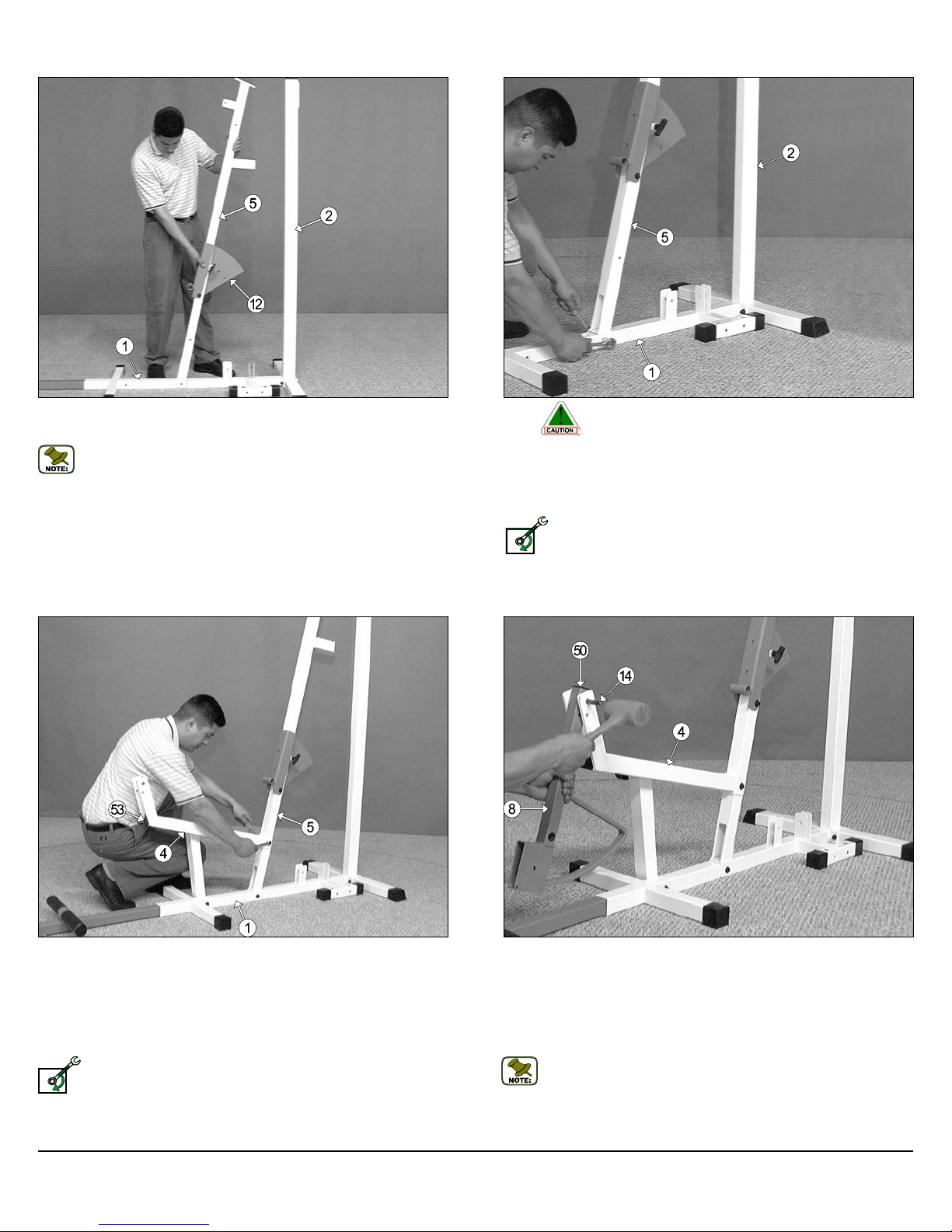
FIG. 7 Attach the Rear Upright (#2) to the Base Frame (#1) and
secure it into place using two Hex Head Cap Screws 3/8-16 X 4-1/4 (#77),
four Flat Washers SAE 3/8” (#60), and two Nylon Insert Lock Nuts 3/8-16
(#69).
Loosely Fasten: Do not completely fasten this hardware
assembly at this time, as it will be completely fastened later in the
LOOSELY FASTEN
assembly process.
CFM-550 Compact Frontal Machine
Page 5
Owner’s Manual: Assembly Instructions
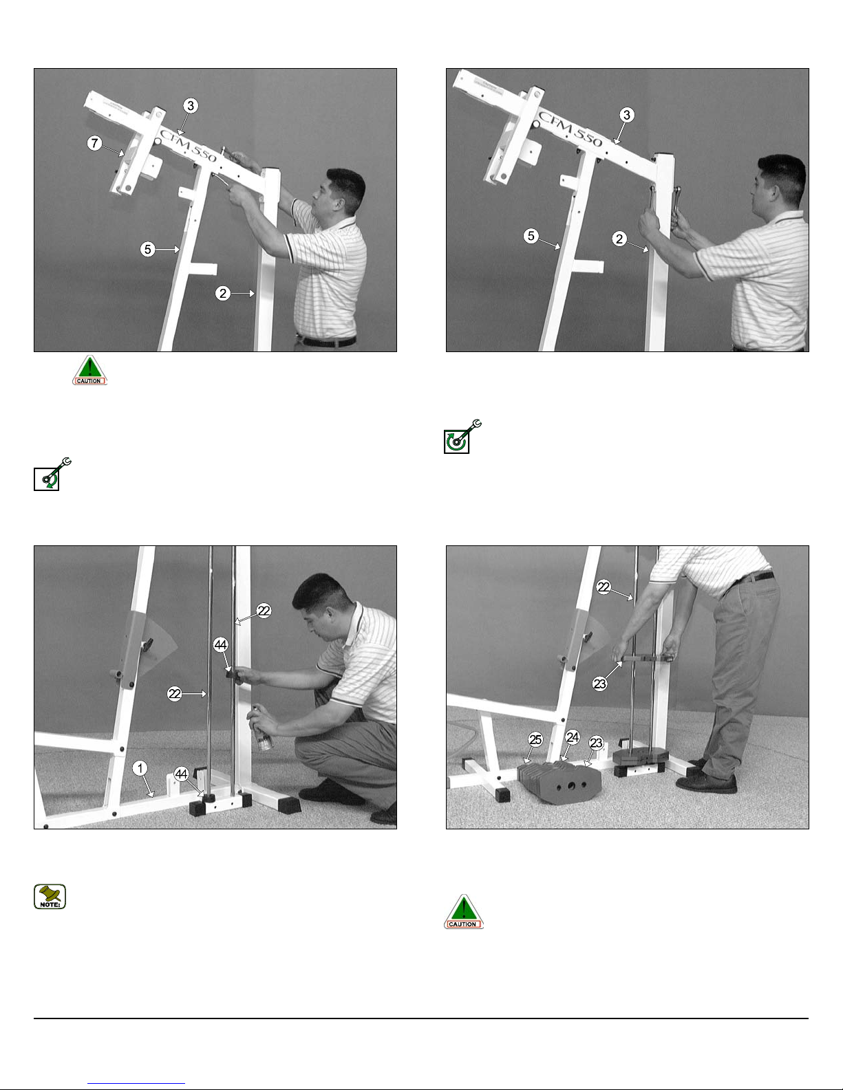
FIG. 8 This picture depicts the position of the Front Upright (#5), and
where it is going to be assembled on the Base Frame (#1).
Note: The Back Pad Bracket (#12) has been pre-assembled to the
Front Upright (#5) by the factory.
FIG. 9 Caution: It is recommended to use another person in as-
sisting with this assembly.
Attach the Front Upright (#5) to the Base Frame (#1) and secure it into
place using one Hex Head Cap Screw 3/8-16 X 2-3/4 (#75), two Flat
Washers SAE 3/8” (#60), and one Nylon Insert Jam Lock Nut 3/8-16
(#68).
Loosely Fasten: Do not completely fasten this hardware
assembly at this time, as it will be completely fastened later in
LOOSELY FASTEN
the assembly process.
FIG. 10 Attach the Leg Extension Bench Frame (#4) to the Base
Frame (#1) and secure it into place using one Hex Head Cap Screw 3/8-
16 X 4-1/2 (#78), two Flat Washers SAE 3/8” (#60), and one Nylon Insert
Jam Lock Nut 3/8-16 (#68). Next, attach the Leg Extension Bench
Frame (#4) to the Front Upright (# 5) and secure it into place using one
Hex Head Cap Screw 3/8-16 X 2-3/4 (#75), two Flat Washers SAE
3/8” (60), and one Nylon Insert Jam Lock Nut 3/8-16 (#68).
Loosely Fasten: Do not completely fasten this hardware
assembly at this time, as it will be completely fastened later in the
LOOSELY FASTEN
assembly process.
Next, using a rubber mallet, insert one Plastic Insert Cap 2” Sq. (#53) into
the front of the Leg Extension Bench Frame (#4).
CFM-550 Compact Frontal Machine
FIG. 11 Locate the Leg Extension Arm (#8), and using a rubber mal-
let, insert one Plastic Insert Cap 1-1/2 Sq. (#50) into the tube-end.
Next, affix the Leg Extension Arm (#8), in the position as shown above,
to the Leg Extension Bench Frame (#4) and secure it into place by inserting the Leg Extension Axle 1/2 X 2-3/4 (#14) through the Leg
Extension Bench Frame (#4) and Leg Extension Arm (#8) until it be-
comes flush with both sides of the Leg Extension Bench Frame (#4).
Note: It is recommended to grease the Leg Extension Axle 1/2 X
2-3/4 (#14) with multi-purpose grease prior to assembling.
4
Page 6
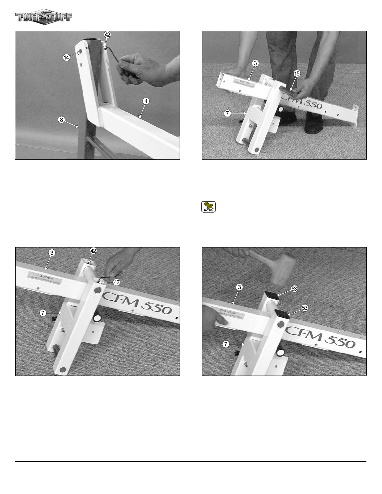
FIG. 12 Next, secure the Leg Extension Axle 1/2 X 2-3/4 (#14) to the
Leg Extension Bench Frame (#4) using two Set Screws 1/4-20 X 3/8
(#42), as shown above. Use the supplied Hex Key 1/8” (#86) for fastening
these Set Screws.
FIG. 13 Insert the Press Bar Selector Housing (#7), in the position as
shown above, to the Top Pulley Housing (#3) and secure it into place by
inserting a Pivot Axle 1 X 8-1/8 (#15) through the receptacle of the Press
Bar Selector Housing (#2) and the Top Pulley Housing (#5) until the
axle becomes flush with both sides of the Press Bar Selector Housing
(#7)
Note: It is recommended to grease the Pivot Axle 1 X 8-1/8 (#15)
with multi-purpose grease prior to assembling.
FIG. 14 Next, secure the Pivot Axle 1 x 8-1/8 (#15) to the Press Bar
Selector Housing (#7) using two Set Screws 1/4-20 X 3/8 (#42), as
shown above. Use the supplied Hex Key 1/8” (#86) for fastening these
Set Screws.
5
FIG. 15 Using a rubber mallet, insert two Plastic Insert Caps 2” Sq.
(#53) into the tube-ends of the Press Bar Selector Housing (#7), as
shown above.
CFM-550 Compact Frontal Machine
Page 7
Owner’s Manual: Assembly Instructions
FIG. 16 Caution: It is recommended to use another person in as-
sisting with this assembly.
Attach the Top Pulley Housing (#3) to the Front Upright (# 5) and secure
it into place using two Hex Head Cap Screws 3/8-16 X 4-1/2 (#78), four
Flat Washers SAE 3/8” (#60), and two Nylon Insert Lock Nuts 3/8-16
(#69).
Loosely Fasten: Do not completely fasten this hardware
assembly at this time, as it will be completely fastened later in the
LOOSELY FASTEN
assembly process.
FIG. 17 Attach the Top Pulley Housing (#3) to the Rear Upright (#2)
and secure it into place using two Hex Head Cap Screws 3/8-16 X 4-1/4
(#77), four Flat Washers SAE 3/8” (#60), and two Nylon Insert Lock Nuts
3/8-16 (#69).
Fully Fasten: Proceed to align and fully fasten this hardware
assembly and all the previous assemblies that were left loosely
fastened. (Assemblies described in Fig.7, Fig.9, Fig.10, and
FULLY FASTEN
Fig.16).
FIG. 18 Insert the two Guide Rods 3/4 X 72 (#22) into the receptacles
located on the Base Frame (#1), as shown above. Slide one Rubber
Donut 3/4 X 2 1/2 (#44) onto each Guide Rod 3/4 X 72 (#22), as shown.
Note: Lubricate the Guide Rods 3/4 X 72 (#22) with silicone or
teflon lubricant before proceeding.
CFM-550 Compact Frontal Machine
FIG. 19 Carefully begin sliding the Weight Plates over the Guide
Rods (#22) beginning with the five 15 Lb. Weight Plates (#23) at the bot-
tom, the nine 10 Lb. Weight Plates (#24) in the middle, and the five 5 Lb.
Weight Plates (#25) on top of the weight stack.
Caution: Do not lift more than you can control safely. In addition,
do not lift using only your back. It is recommended that when you
are lifting, bend your knees and lift slowly with your back straight.
Be sure that the weight is distributed over your knees or legs
when lifting. Also, it is advisable to wear a well fitted lifting belt
during heavy lifting.
6
Page 8
Label
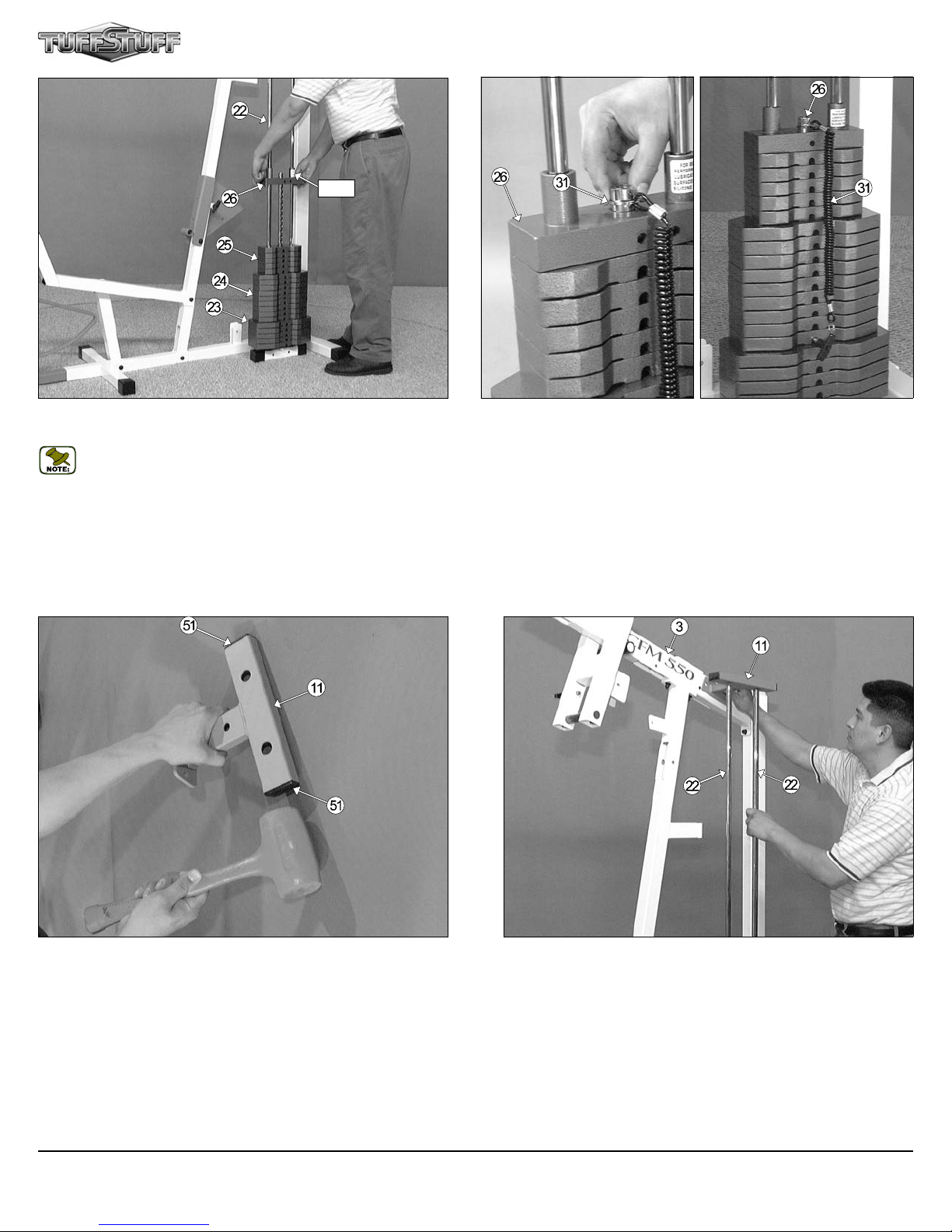
FIG. 20 Now slide the Top Plate/Selector Bar (#26) over the Guide
Rods (#22) allowing it to come to rest on the completed weight stack.
Note: Be sure the Label located on the Top Plate/Selector Bar
(#26) is facing toward you before you slide the Top Plate/Selector
Bar (#26) over the Guide Rods 3/4 X 72 (#22).
FIG. 21 Next, locate the Selector Pin w/Coil (#31) and slide its ring
over the Selector Bar (#26) as shown above.
FIG. 22 Locate the Guide Rod Retainer Housing (#11) and, using a
rubber mallet, insert two Plastic Insert Caps 1 X 2 ( #51) into the tubeends, as shown above.
7
FIG. 23 Maneuver each one of the Guide Rod s (#22) into the holes located on the bottom side of the Guide Rod Retainer Housing (#11), as
shown above.
CFM-550 Compact Frontal Machine
Page 9
Owner’s Manual: Assembly Instructions
FIG. 24 Mount the Guide Rod Retainer Housing (#11) along with the
two captive Guide Rods (#22) to the side of the Top Pulley Housing
(#3), as shown above, and secure them into place using two Hex Head
Cap Screws 3/8-16 X 3-1/4 (#76), four Flat Washers SAE 3/8” (#60), and
two Nylon Insert Lock Nuts 3/8-16 (#69).
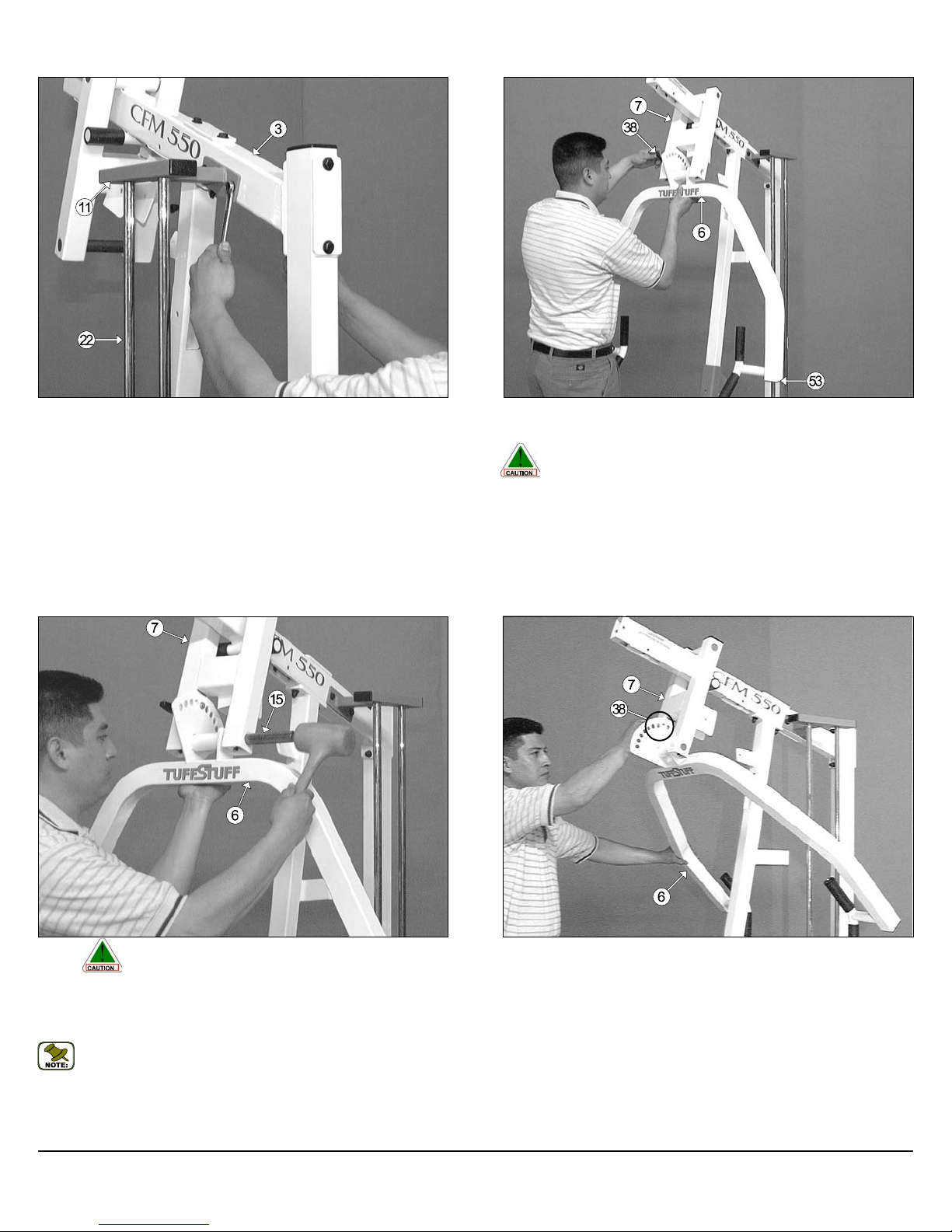
FIG. 25 Next, using a rubber mallet, insert two Plastic Insert Caps 2"
Sq. (#53-Not shown) into the tube-ends of the Press Bar (#6).
Caution: It is recommended to use another person in assisting
with this assembly.
Insert the Press Bar (#6) up into the Press Bar Selector Housing (#7)
and support it into place using the Push-Pull Pin 1/2 X 3-1/2 (#38), as
shown above.
FIG. 26 Caution: It is recommended to use another person in as-
sisting with this assembly.
Insert a Pivot Axle 1 X 8-1/8 (#15) into the Press Bar Selector Housing
(#7) and through the Press Arm (#6) until it becomes flush with both sides
of the Press Bar Selector Housing (#7).
Note: It is recommended to grease the Pivot Axle 1 X 8-1/8 (#15)
with multi-purpose grease prior to assembling.
CFM-550 Compact Frontal Machine
FIG. 27 Adjust the Press Bar (#6) to the far back Press Bar Setting, as
shown above, and release the Push-Pull Pin 1/2 X 3-1/3 (#38) to lock the
Press Bar (#6) into this position.
8
Page 10

FIG. 28 Secure the Press Bar (#6) into the Press Bar Selector Hou s-
ing (#7) by threading the two Set Screws 1/4-20 X 3/8 (#42), located on
Press Bar Selector Housing (#7), against the Pivot Axle (#15) using the
supplied Hex Key 1/8” (#86).
Fig. 29 Next, using a rubber mallet, insert two Plastic Insert Caps 2 Sq.
(#53) into the tube-ends of the Press Bar Selector Housing (#7), as
shown above.
FIG. 30 Next, apply a 1" Rd. Silver Mylar Decal (#88) over each end of
the two Pivot Axles (#15). These Decals are used to hide and protect the
ends of the Pivot Axles (#15).
9
FIG. 31 Attach the Lat Bar Holder (#13), in the position as shown
above, to the Top Pulley Housing (#3) and secure it into place using one
Hex Head Cap Screw 3/8-16 X 2-3/4 (#75), two Flat Washers SAE
3/8” (#60), and one Nylon Insert Jam Lock Nut 3/8-16 (#68).
CFM-550 Compact Frontal Machine
Page 11

Owner’s Manual: Assembly Instructions
Fig. 32 Assemble the Adjustable Pulley Bracket (#17) using one
Nylon Pulley 4-1/2 Rd. (#45-Labeled H), one Hex Head Cap Screw 3/8-16
X 1-3/4 (#73), two Flat Washers SAE 3/8” (#60), and one Nylon Insert
Jam Lock Nut 3/8-16 (#68). Next, thread a Regular Hex Nut 1/2-13 (#70),
and insert one Split Washer B.O. 1/2” (#89) onto the welded Hex Tap Bolt.
Next, locate the Adjustable Stopper (#21) then thread a Regular Hex Nut
1/2-13 (#70), and insert one Split Washer B.O. 1/2” (#89) onto the welded
Hex Tap Bolt.
Note: The black boxed letters pointing to the pulleys are used
throughout this manual as reference to the Cable Mapping Diagram
on page 20. These black boxed letters will be primarily used for
locating certain pulleys during the cable routing process beginning
with Fig. 32.
FIG. 33 Insert the welded bolt of the Adjustable Pulley Bracket (#17)
through the hole located on the Guide Rod Retainer Housing (#11) and
secure it into place at the top using one Flat Washer SAE 1/2” (#61), and
one Nylon Insert Jam Lock Nut 1/2-13 (#71).
Loosely Fasten: Do not completely fasten this hardware assembly at this time, as it will be completely fastened later in the as-
LOOSELY FASTEN
sembly process.
Note: Refer to Fig. 65 on page 19 for further clarification of this
assembly.
FIG. 34 Insert (from bottom to top) the Adjustable Stopper (#21) into
the receptacle of the Front Upright (#5) and secure it int o place using
one Split Washer B.O. 1/2” (#89), and one Regular Hex Nut 1/2-13 (#70),
as shown above. Loosely fasten the Regular Hex Nuts 1/2-13 (#84) to
allow adjustment of cable’s tension later in the assembly process.
Note: Refer to Fig. 66 on page 19 for further clarification of this
assembly.
CFM-550 Compact Frontal Machine
FIG. 35 Insert one Nylon Pulley 4-1/2 Rd. (#45-Labeled A) into the Top
Pulley Housing (#3), in the position as shown above, and secure it into
place using one Hex Head Cap Screw 3/8-16 X 2-1/2 (#74), two Flat
Washers SAE 3/8” (#60), and one Nylon Insert Jam Lock Nut 3/8-16
(#68). Next, begin routing the Lat Cable (#27) over the Nylon Pulley 4 1/2
Rd. (#45-Labeled A) and into the tube of the Top Pulley Housing (#3), as
shown above.
10
Page 12

FIG. 36 Next, route the end of the Lat Cable (#27) through the opening
located at the bottom of the Top Pulley Housing (#3). Then insert a
Nylon Pulley 4-1/2 Rd. (#45-Labeled B) into this slot and secure the Nylon
Pulley 4-1/2 Rd. (#45-Labeled B) into place using one Hex Head Cap
Screw 3/8-16 X 2-1/2 (#74), two Flat Washers SAE 3/8” (#60), and one
Nylon Insert Jam Lock Nut 3/8-16 (#68). Be sure the cable is routed properly into the groove on the Nylon Pulley 4-1/2 Rd. (#45-Labeled B).
Note: Use Cable Mapping Diagram on page 20 for further deta iled
illustration of the Lat Cable (#27) routing.
FIG. 37 Install two Nylon Pulleys 4-1/2 Rd. (#45-Labeled C, E) into the
pulley bracket located on the Press Bar Selector Housing (#7) and
secure them into place using one Hex Head Cap Screw 3/8-16 X 2-3/4
(#75), two Flat Washers SAE 3/8” (#60), and one Nylon Insert Jam Lock
Nut 3/8-16 (#68).
FIG. 38 Next, install one Nylon Pulley 4-1/2 Rd (#45-Labeled D) onto
the pulley plate located on the Front Upright (#5), in the position as
shown above, and secure it into place using one Hex Head Cap Screw
3/8-16 X 1-3/4 (#73), two Flat Washers SAE 3/8” (#60), one Cable
Retainer Bracket (#20), and one Nylon Insert Jam Lock Nut 3/8-16 (#68).
Note: Be sure to position the Cable Retainer Bracket (#20) as
shown above.
Next, insert one Nylon Pulley 4-1/2 Rd. (#45-Labeled F) into the slot located on the Front Upright (#5) and secure it into place using one Hex
Head Cap Screw 3/8-16 X 2-1/2 (#74), two Flat Washers SAE 3/8” (#60),
and one Nylon Insert Jam Lock Nut 3/8-16 (#68).
11
Fig. 39 Assemble the Adjustable Double Pulley Bracket (#16) using
two Nylon Pulleys 4-1/2 Rd. (#45-Labeled G, K), two Hex Head Cap
Screws 3/8-16 X 1-3/4 (# 73), four Flat Washers SAE 3/8” (#60), and two
Nylon Insert Jam Lock Nuts 3/8-16 (#68).
Note: The fo ur holes on the Adjustable Double Pulley Bracket
(#16) are used to adjust the cable tension once the cable routing
has been completed.
CFM-550 Compact Frontal Machine
Page 13

Owner’s Manual: Assembly Instructions
FIG. 40 Next, route the Lat Cable (#27) over the Nylon Pulley 4-1/2
Rd. (#45-Labeled C), then up and over the Nylon Pulley 4-1/2 Rd. (#45Labeled D).
Note: Use Cable Mapping Diagram on page 20 for further detailed
illustration of the Lat Cable (#27) routing.
FIG. 41 Next, route the Lat Cable (#27) over the Nylon Pulley 4-1/2
Rd. (#45-Labeled E), as shown above.
Note: Use Cable Mappin g Diagram on page 20 for further detailed
illustration of the Lat Cable (#27) routing.
FIG. 42 Next, route the Lat Cable (#27) through the Front Upright
(#5) and over the Nylon Pulley 4-1/2 Rd. (#45-Labeled F), as shown.
CFM-550 Compact Frontal Machine
FIG. 43 Next, route the Lat Cable (#27) through the Adjustable Dou-
ble Pulley Bracket (#16) and under the Nylon Pulley 4 1/2 Rd. (#45-
Labeled G), as shown above.
Note: Use Cable Mapping Diagram on page 20 for further detailed
illustration of the Lat Cable (#27) routing.
12
Page 14

FIG. 44 Next, route the Lat Cable (#27) through the Adjustable Pulley
Bracket (#17) and over the Nylon Pulley 4 1/2 Rd. (#45-Labeled H), as
shown above.
Note: Use Cable Mapping Diagram on page 20 for further detailed
illustration of the Lat Cable (#27) routing.
FIG. 45 Next, attach the Lat Cable (#27) to the Top Plate/ Selector
Bar (#26) and secure it into place using one Split Bolt 1/2-13 (#64), and
one Split Washer 1/2” (#63). Refer to Fig. B on page 20 for further
illustration of this hardware assembly.
Fully Fasten: Proceed to fully fasten this hardware assembly.
FULLY FASTEN
FIG. 46 Next, install a Nylon Pulley 4-1/2 Rd. (#45-Labeled I) into the
pulley bracket located on the Leg Extension Arm (#8) and secure it into
place using one Hex Head Cap Screw 3/8-16 X 1-3/4 (#73), two Flat
Washers SAE 3/8” (#60), and one Nylon Insert J am Lock Nut 3/8-16
(#68). Next, route the Leg Extension Cable (#28) under the Nylon Pulley
4-1/2 Rd. (#45-Labeled I), then secure it into place using one Hex Head
Cap Screw 1/4-20 X 1-1/2 (#63), and one Nylon Insert Lock Nut 1/4-20
(#64).
Note: Refer to Fig. C on page 20 for further illustration of this
assembly.
13
FIG. 47 Next, route the Leg Extension Cable (#28) through the Front
Upright (#5), then under the Nylon Pulley 4-1/2 Rd. (#45-Labeled J).
Secure the Nylon Pulley 4-1/2 Rd. (#45-Labeled J) into place using one
Hex Head Cap Screw 3/8-16 X 1-3/4 (#73), two Flat Washers SAE
3/8” (#60), and one Nylon Insert Jam Lock Nut 3/8-16 (#68).
Note: Use Cable Mapping Diagram on page 20 for further detailed
illustration of the Leg Extension Cable (#28) routing.
CFM-550 Compact Frontal Machine
Page 15

Owner’s Manual: Assembly Instructions
FIG. 48 Lift the end of the Leg Extension Cable (#28) and route it
through the Adjustable Double Pulley Bracket (#16) and over the Nylon
Pulley 4-1/2 Rd. (#45-Labeled K), as shown above.
Note: Use Cable Mapping Diagram on page 20 for further detailed
illustration of the Leg Extension Cable (#28) routing.
FIG. 49 Connect the looped end of the Leg Extension Cable (#28) to
the pulley bracket located on the Base Frame (#1), as shown above.
Secure this assembly using one Hex Head Cap Screw 3/8-16 X 1-3/4
(#73), two Flat Washers SAE 3/8” (#60), two Nylon Spacers 3/8 X 3/8
(#52), and one Nylon Insert Jam Lock Nut 3/8-16 (#68).
Note: Refer to Fig. D on page 20 for further illustration of this
assembly.
FIG. 50 Next, using a rubber mallet, insert one Plastic Insert Cap 1 X 2
(#51) into the tube-end of the Bench Press Adj. Seat Frame (#9). Next,
locate the Seat Pad (#33) and attach it to the Bench Press Adj. Seat
Frame (#9), as shown above, using two Hex Head Cap Screws 3/8-16 X
1-3/4 (#73), and two Flat Washers SAE 3/8” (#60).
CFM-550 Compact Frontal Machine
FIG. 51 Insert the Bench Press Adj. Seat Frame (#9) into the Leg Ex-
tension Bench Frame (#4), in the position as shown above. Be sure to
release the Turn/Pull Pin w/Knob (#39) as you begin to insert the assembled Bench Press Adj. Seat Frame (#9) into the Leg Extension Bench
Frame (#4).
14
Page 16

FIG. 52 Next, insert one Foot Roll Tube 1 X 16 (#18) into the recepta-
cle located on the Bench Press Adj. Seat Frame (#9). Then, insert the
other Foot Roll Tube 1 X 16 (#18) into the receptacle loc ated on the Leg
Extension Arm (#8). Next, insert the Foot Roll Tube 1 X 23-3/4 (#19)
into the receptacle located on the Adjustable Back Pad Bracket (#12),
as shown above. Be sure all these tubes are centered at the receptacles
from end-to-end.
10
-
1/2”
FIG. 53 Secure the Foot Roll Tube 1 X 16 (# 18) to the Bench Press
Adj. Seat Frame (#9) using a Set Screw 1/4-20 X 1/4 (#43). Use the
supplied Hex Key 1/8” (#86) for securing the Set Screw 1/4-20 X 1/4 (#43)
into the threaded socket located on the Bench Press Adj. Seat Frame
(#9).
Note: Refer to Fig. 67 on page 19 for further illustration of this
assembly.
FIG. 54 Secure the Foot Roll Tube 1 X 23-3/4 (#19) to the Adjustable
Back Pad Bracket (#12) using a Set Screw 1/4-20 X 1/4 (#43). Use the
supplied Hex Key 1/8” (#86) for securing the Set Screw 1/4-20 X 1/4 (#43)
into the threaded socket located on the Adjustable Back Pad Bracket
(#12).
Note: Refer to Fig. 68 on page 19 for further illustration of this
assembly. In addition, a measuring tape is used to center the Foot
Roll Tube 1 X 23-3/4 (#19). The measurement from one end of the
tube to the receptacle, as pictured above, should be about 10-1/2”.
15
FIG. 55 insert one Foam Foot Roll 7 X 4 X 1 (#46) onto each end of
the three Foot Roll Tubes, as shown above. Refer to the Exploded View
Diagram on page 21 for further clarification of this assembly.
CFM-550 Compact Frontal Machine
Page 17

Owner’s Manual: Assembly Instructions
FIG. 56 Next, using a rubber mallet, insert one Foot Roll Plastic End
Cap 1” (#55) into each end of the three Foot Roll Tubes, as shown
above. Refer to the Exploded View Diagram on page 21 for further clarification of this assembly.
FIG. 57 Mount the Back Pad (#32) to the Back Pad Bracket (# 12) and
secure into place using two Hex Head Cap Screws 3/8-16 X 1-1/4 (#72),
and two Steel Bumper Washers 3/8” (#59). Cap-off the two Steel Bumper
Washers 3/8” (#59-Not shown) using two Bumper Caps (#58).
Note: Refer to Fig. 69 on page 19 for further clarification of this
assembly.
FIG. 58 Insert one Rubber Grip 1 X 6 (#90) over each one of the tubeends of Low Row Bar 20” (#29) and the Lat Bar 48” (#30), as shown
above.
Note: To facilitate the insertion of these Rubber Grips, use Windex
or household glass cleaner.
CFM-550 Compact Frontal Machine
FIG. 59 Next, attach a Snap Link (#81) to the Lat Cable (#27) and secure it into place using one Shoulder Bolt 3/8 X 3/4 (#82), and one Nylon
Insert Lock Nut 5/16-18 (#67). Use the supplied Hex Key 3/16” (#85) and
a 1/2” combination wrench to fasten this assembly properly.
Note: Refer to Fig. A on page 20 for further illustration of this
assembly.
16
Page 18

FIG. 60 Connect the Lat Bar 48” (#30) to the Lat Cable (#27) using
the Snap Link (#81), as shown above. Use the Lat Bar Holder (#13) to
rest the Lat Bar 48” (#30) onto when not in use.
FIG. 62 Multiple exercise starting positions can be achieved by using
the Coil Chain (#80) as an extension to connect the Lat Bar (#30) or the
Low Row Bar (#29) to the Lat Cable (#27) with out loosing traveling
range on the Weight Stack.
FIG. 61 Locate the Coil Chain (#80) and two Snap Links (#81), and
attach them to the Low Row Bar 20” (#15) and to the Leg Extension
Cable (#28), as shown above.
15
20
25
30
35
45
55
65
75
85
95
105
115
125
140
155
170
185
200
FIG. 63 Attach the Decal Weight Numbers (#87) to the Weight Plates
(#23, #24, #25) in the corresponding order. Begin with the 15 at the top,
20 next, and so on.
17
CFM-550 Compact Frontal Machine
Page 19

to make contact
) to
Adjustable Double Pulley
Adjustable Stopper
Lock Nut (#58) to give
) to
Remove the hardware from the Nylon Pulley 4 1/2 Rd.
Adjustable
d. (#45) in
tighten the hardware for Nylon Pulley 4 1/2 Rd.
CFM-550 CABLE ADJUSTMENTS DIAGRAM
Cable Adjustment for:
Adjustable Pulley Bracket (#17)
1. Loosen the bottom Regular Hex Nut (#70).
2. Adjust the top Nylon Insert Jam
the cable proper tension.
3. Re-tighten the bottom Regular Hex Nut (#70
complete the cable adjustment.
Adjustable Stopper (#21)
1. Loosen both Regular Hex Nuts 1/2-13 (#70).
2. Adjust the Adjustable Stopper (#21)
with the Adjustable Double Pulley Brkt. (#16).
3. Re-tighten both Regular Hex Nuts 1/2-13 (#70
complete the adjustment.
Note: Be sure that the
Brkt. (#16) is resting on the
(#21).
Adjustable Double Pulley Brkt. (#16)
1.
(#45) located at one of the four holes on the
Double Pulley Brkt. (#16).
2. By interchanging the Nylon Pulley 4 1/2 R
the Adjustable Double Pulley Brkt. (#16) to the next adjustment hole it will make one inch cable adjustment.
3. Re(#45) to complete the cable adjustment.
Adjustment for:
Cable Adjustment for:
CFM-550 Compact Frontal Machine
18
Page 20

FIG. 64
FIG. 65
FIG. 66
FIG. 68
FIG. 67
FIG. 69
19
CFM-550 Compact Frontal Machine
Page 21

FIG. C
FIG. A
CFM-550 CABLE MAPPING DIAGRAM
FIG. D
CFM-550 Compact Frontal Machine
FIG. B
20
Page 22

CFM-55
0 EXPLODED VIEW DIAGRAM
21
CFM-550 Compact Frontal Machine
Page 23

RUBBER GRIP 1.1875 ID X .125 X 5-1/4
DECAL-NUMBERS W/INCREMENTS 200,15,10,5 LBS
TURN/PULL PIN W/KNOB
CFM-550 PARTS LIST
COLOR CHART
GRAY= SUB-ASSEMBLY PARTS
BLACK= HARDWARE
Item No. Description Part No. Qty Item No. Description Part No. Qty
1 BASE FRAME UP682 1 50
2 REAR UPRIGHT UP685 1 51
3 TOP PULLEY HOUSING UP684 1 52
4 LEG EXTENSION BENCH FRAME UP555 1 53
5 FRONT UPRIGHT UP683 1 54
6 PRESS BAR UP321 1 55 FOOT ROLL PLASTIC END CAP 1" BNH0397 6
7 PRESS BAR SELECTOR HOUSING UP681 1 56
8 LEG EXTENSION ARM UP325 1 57
9 BENCH PRESS ADJ. SEAT TUBE UP171 1 58
10 LOW ROW FOOT ASSEMBLY UP686 1 59
11 GUIDE ROD RETAINER HOUSING UP169 1 60
12 BACK PAD BRACKET UP179 1 61
13 LAT BAR HOLDER UP327 1 62
14 LEG EXTENSION AXLE 1/2 X 2-3/4 UP373 1 63
15 PIVOT AXLE 1 X 8-1/8 UP152 2 64
16 ADJ. DOUBLE PULLEY BRKT. UP689 1 65
17 ADJ. PULLEY BRACKET UP127 1 66
18 FOOT ROLL TUBE 1 X 16 UP053 2 67
19 FOOT ROLL TUBE 1 X 23-3/4 UP180 1 68
20 CABLE RETAINER BRACKET UP014 1 69
21 ADJUSTABLE STOPPER UP331 1 70
22 GUIDE ROD 3/4 X 72 UP124
23
15 LB WEIGHT PLATE BNH0926 5
24
10 LB WEIGHT PLATE BNH0904 9
25
5 LB WEIGHT PLATE BNH0927 5
26
TOP PLATE/ SELECTOR BAR BNH0932 1
27 LAT CABLE UP687 1 76
28 LEG EXTENSION CABLE UP688 1 77
29 LOW ROW BAR 20" BNH0294 1 78
30 LAT BAR 48" BNH0295 1 79
31 SELECTOR PIN W/COIL UP466 1 80
32 BACK PAD UP128 1 81
33 SEAT PAD UP173 1 82
34
SAFETY TAPE ANTI SLIP 2" X 6-3/4" BNH0491 4
35
BRONZE BUSHING 1 X 1-1/4 BNH0527 4
36
BRONZE BUSHING 1/2 X 5/8 BNH0528 2
37
38
PUSH PULL PIN 1/2 X 3-1/2 BNH0520 2
39
40
RUBBER STOPPER 1 ID X .187 X 3 BNH0976 2
41
NYLON STEM BUTTON BNH0533 1
42
SET SCREW 1/4-20 X 3/8 BNH0772 6
43 SET SCREW 1/4-20 X 1/4 BNH0790 2 92 DECAL-CAUTION LAT BAR HOLDER 5 X 1 BNH0140 1
44
RUBBER DONUT 3/4 X 2-1/2 BNH0068 2
45
WHITE NYLON PULLEY 4-1/2 RD. BNH0556 11
46
FOAM FOOT ROLL 7 X 4 X 1 BNH0043 6
47
PLASTIC END CAP W/ GROOVE 2" SQ. BNH0136 4
48
PLASTIC END CAP W/GROOVE 2 X 3 BNH0049 2
49
PLASTIC INSERT CAP 1-1/4 RD. BNH0573 4
BNH0937 4
BNH0929 1
2
PLASTIC INSERT CAP 1-1/2 SQ. BNH0009 1
PLASTIC INSERT CAP 1 X 2 BNH0005 3
NYLON SPACER 3/8 X 7/8 X 3/8 BNH0392 2
PLASTIC INSERT CAP 2" SQ. BNH0012 7
PLASTIC INSERT CAP 2 X 3 BNH0052 1
PLASTIC END CAP 2" RD. BNH0004 2
PLASTIC INSERT CAP 1-3/4 SQ. BNH0053 1
BUMPER CAP BLACK BNH0412 2
STEEL BUMPER WASHER 3/8 BNH0498 2
FLAT WASHER SAE 3/8" BNH0239 48
FLAT WASHER SAE 1/2" BNH0238 1
FLAT WASHER USS NYLON 3/8" BNH0248 4
SPLIT WASHER 1/2" BNH0572 1
SPLIT BOLT 1/2-13 X 1 BNH0479 1
HEX HEAD CAP SCREW 1/4-20 X 1-1/2 BNH0272 1
NYLON INSERT LOCK NUT 1/4-20 BNH0213 1
NYLON INSERT LOCK NUT 5/16 -18 BNH0215 1
NYLON INSERT JAM LOCK NUT 3/8-16 BNH0365 16
NYLON INSERT LOCK NUT 3/8-16 BNH0214 8
REGULAR HEX NUT 1/2-13 BNH0201 3
71
NYLON INSERT JAM LOCK NUT 1/2-13 BNH0366 1
72
HEX HEAD CAP SCREW 3/8-16 X 1-1/4 BNH0273 2
73
HEX HEAD CAP SCREW 3/8-16 X 1-3/4 BNH0274 9
74
HEX HEAD CAP SCREW 3/8-16 X 2-1/2 BNH0276 3
75
HEX HEAD CAP SCREW 3/8-16 X 2-3/4 BNH0278 4
HEX HEAD CAP SCREW 3/8-16 X 3-1/4 BNH0312 3
HEX HEAD CAP SCREW 3/8-16 X 4-1/4 BNH0317 4
HEX HEAD CAP SCREW 3/8-16 X 4-1/2 BNH0284 3
L-LOCKING PIN BNH0045 1
COIL CHAIN 3/16 X 21 BNH0017 1
SNAP LINK BNH0065 3
SHOULDER BOLT 3/8 X 3/4 BNH0718 1
83
NYLON BALL 1-3/4 X 1/4 BNH0047 2
84
STRAP BRACKET #20 BNH0562 1
85
HEX KEY 3/16" BNH0371 1
86
HEX KEY 1/8" BNH0767 1
87
88
1" RD. SILVER MYLAR DECAL BNH0015 4
89
SPLIT WASHER B.O. 1/2" BNH0653 3
90
RUBBER GRIP 1 X 6 BNH0296 4
91
LABEL-CAUTION 1-1/2 X 5.5 BNH0131 1
93
DECAL-FOR BEST PERFORMANCE 1-1/4 X 1-1/2 BNH0143 1
94
DECAL-ADJUST CABLE HERE BNH0789 2
95
DECAL-DANGER TIGHTEN THIS RET..., 3/4 X 1-1/2 BNH0142 2
96
DECAL-TUFF STUFF SIZE 1-3/8 X 8-7/16 BNH0139 1
97
DECAL CFM-550 BNH1058 2
98
EXERCISE WALL CHART BNH0745 1
BNH0928 1
CFM-550 Compact Frontal Machine
22
Page 24

Adjustment Features
Press Bar Range of Adjustable Settings
♦ Used for Seated Row Exercise.
Setting A - C
♦ Used for Chest Press Exercise.
Setting D - F
♦ Used for Shoulder Press Exercise.
Setting G - I
Fig. 70 Illustration of the Press Bar’s adjustable settings used on
multiple Exercise Starting Positions.
Fig. 71 Press Bar (#6) adjustment:
1. Grasp the Press Bar (#6)
2. Pull the Push Pull Pin 1/2” X 3-1/2 (#38) to release the Press Bar (#6).
3. Adjust the Press Bar (#6) to the desired position.
4. Release the Push Pull Pin 1/2” X 3-1/2 (#38) and make sure it fully
engages into the selected hole of the Press Bar ’s (#6) Plate.
23
CFM-550 Compact Frontal Machine
Page 25

Adjustment Features
Fig. 72 Back Pad (#32) adjustment:
1. Grasp the Back Pad (#32).
2. Pull the Push Pull Pin 1/2” X 3-1/2 (#38) to release the Back Pad
Bracket (#12) from the Front Upright (#5).
3. Adjust the Back Pad (#32) to one of the three available positions.
4. Release the Push Pull Pin 1/2” X 3-1/2 (#38) and make sure it fully
engages into the selected hole of the Back Pad Bracket (#12).
Fig. 73 Seat Pad (#33) adjustment:
1. Grasp the Seat Pad (#33).
2. Turn counterclockwise then pull the Turn/Pull Pin w/Knob (#39) to release
the Bench Press Adj. Seat Tube (#9) from the Leg Extension Bench
Frame (#4).
3. Adjust the Seat Pad (#33) to a desired height.
4. Release the Turn/Pull Pin w/Knob (#39) and make sure it fully engages
into the selected hole of the Bench Press Adj Seat Tube (#9).
5. Complete the adjustment by turning the Turn/Pull Pin w/Knob (#39)
clockwise.
Fig. 74 Locking the Leg Extension Arm (#8)
1. Locate the L-Locking Pin (#79).
2. Insert the L-Locking Pin (#79) through the Leg Extension Bench
Frame (#4) and the Leg Extension Arm (#8), as shown above.
Unlocked Leg Extension Arm used on Exercises:
♦ Leg Extension
♦ Leg Curl
Locked Leg Extension Arm used on Exercises:
♦ Low Row
♦ Standing Arm Curl
♦ Inner / Outer Thigh
♦ Seated Row
♦ Seated Chest Press
♦ Seated Shoulder Press
CFM-550 Compact Frontal Machine
Fig. 75 Weight Selection
1. Grasp the Weight Selector Pin (#31).
2. Insert the Weight Selector Pin (#31) into desired Weight Plate. The
Decal Weight Number (#87) on the selected Weight Plate will show
the amount of weight selected. The Top/Plate Selector Bar (#26)
must be resting on top of the Weight Stack.
3. Make sure the Weight Selector Pin (#31) has been fully inserted into
the selected Weight Plate.
24
Page 26

Maintenance
M aintenance Information
1. Lubrication of all moving parts is essential to the longevity
and optimal performance of your Compact Frontal
Machine. Initial lubrication of some parts of your gym
have been done at the factory, but the weight stack guide
rods must be lubricated at the time of assembly. We
recommend a clear aerosol, silicone or teflon spray.
Note: Do not use oil based lubricants as they will attract
dust,dirt and grime, and will eventually gum up and erode
bushings and sealed bearings.
2. All pulleys and bushings should be checked regularly for
signs of wear.
3. Check and adjust cable tension periodically as it will
maintain proper anatomical function.
4. Periodically check all moving parts, upholstery and grips
for signs of wear or damage. If there is a problem or
replacement part is necessary, STOP USING THE
EQUIPMENT and immediat ely contact your local Tuff Stuff
retailer or call our Customer Service Department. Replace
parts using only genuine Tuff Stuff parts.
5. As needed, upholstery may be cleaned with a mild
solution of soap and water. Regular use of a vinyl
treatment will add to the life and appearance of your
upholstery.
6. All chrome plated surfaces should be cleaned regularly to
prolong the life and luster of the finish. Wipe machine
down with a damp cloth and dry thoroughly each day. At
least once a week your chrome equipment should be
polished with a commercial grade or automotive type
chrome polish.
7. When checking the bolts and nuts, be sure they are all
fully fastened. If there is a bolt or nut that continuously
loosens obtain a replacement through your local Tuff Stuff
retailer or call our Customer Service Department.
8. Check that the Push Pull Pin 1/2 X 3-1/2 (#38) Hex Nuts
are fully fastened (See Fig. 76). In addition, be sure the
springs in the Push Pull Pins 1/2 X 3-1/2 (#38) are
operating freely.
9. Check welds to be free of cracks.
10. Failure to perform routine maintenance could result in
personal injury and/or equipment damage.
Correct
Push Pull Pin
Hex Nut
Fully Fastened.
Incorrect
Push Pull Pin
Hex Nut
Loosely Fastened.
Fig. 76 Caution: Be sure the Push Pull Pin Hex nuts are fully fastened.
Fasten if necessary.
25
CFM-550 Compact Frontal Machine
Page 27

Notes
CFM-550 Compact Frontal Machine
26
Page 28

DO NOT DISCARD THIS MANUAL
HOME LIFETIME WARRANTY
TuffStuff products are warranted to the retail purchaser to be free from defects in materials and workmanship.
TuffStuff exclusive Home Lifetime Warranty coverage extends for the life of the product while owned by the
original retail purchaser, and used only in a home or residential setting unless otherwise noted in the owner’s
manual.
This warranty does not cover:
1. TuffStuff products sold for and used in a commercial or institutional setting.
2. Any damage, failure or loss caused by accident, misuse, neglect, abuse, improper assembly, improper
maintenance, or failure to follow instructions or warnings in the owner’s manual and warning labels
posted on the machine.
3. Use of products in a manner for which they were not designed.
4. Original product that is altered, or the use of replacement parts and components of another manufacturer other than TuffStuff.
Limitations:
The foregoing shall constitute the sole remedy of the purchaser and the sole liability of TuffStuff with regard to
warranty, whether express or implied by operation of law or otherwise, including but not limited to any implied
warranties of merchantability or fitness. TuffStuff shall in no event be liable for incidental or consequential
losses, damages or expenses in connection with exercise products. TuffStuff’s liability hereunder is expressly
limited to the repairs or replacements of warranted defective parts.
Procedures:
Warranty service will be performed at TuffStuff’s facility in Pomona, California. TuffStuff will have the option of
either repair or replacement at no charge for any defective product. Purchaser is responsible for installation of
repaired or replaced parts and all transportation and insurance costs on returned or replaced equipment to and
from TuffStuff’s facility in Pomona.
This warranty gives you specific legal rights and you may also have other rights, which may vary from state to
state. Effective July 1, 2004.
This warranty is the final, complete and exclusive agreement of the parties with respect to the quality or performance of the equipment
and no action for breach of this written warranty or any implied warranty shall be commenced more than one (1) year after the accrual
of the cause of action. No modification of this warranty or waiver of its terms shall be binding on either party unless approved in
writing by an authorized representative of the party. Contact TuffStuff at 1325 E. Franklin Avenue, Pomona, California 91766, before
returning any defective equipment.
Note: Retain your sales receipt and be sure to mail in the warranty registration card to insure that a
permanent record of your purchase is on file with the factory and to avoid unnecessary delays in
warranty service.
TASK INDUSTRIES, INC.
1325 E. Franklin Ave., Pomona, CA 91766
Ph: 909-629-1600 Fax: 909-629-4967
E-mail: service@tuffstuff.net Net: www.tuffstuff.net
 Loading...