

Page 1
OWNER’ S MANUAL
TABLE OF CONTENTS:
Introduction - Pg. 1
Safety Precautions - Pg. 2
Assembly for BRT-1 - Pg. 3 - Pg. 17
Cable Adjustments - Pg. 18
Cable Mapping Diagrams
Pg. 19 - Pg. 20
Parts List - Pg. 21
Exploded View Diagram
Fold-Out Pg. 22
Adjustment Features - Pg. 23- Pg. 25
Basic Exercises - Pg. 26
Maintenance - Pg. 27
Warranty - Back Page
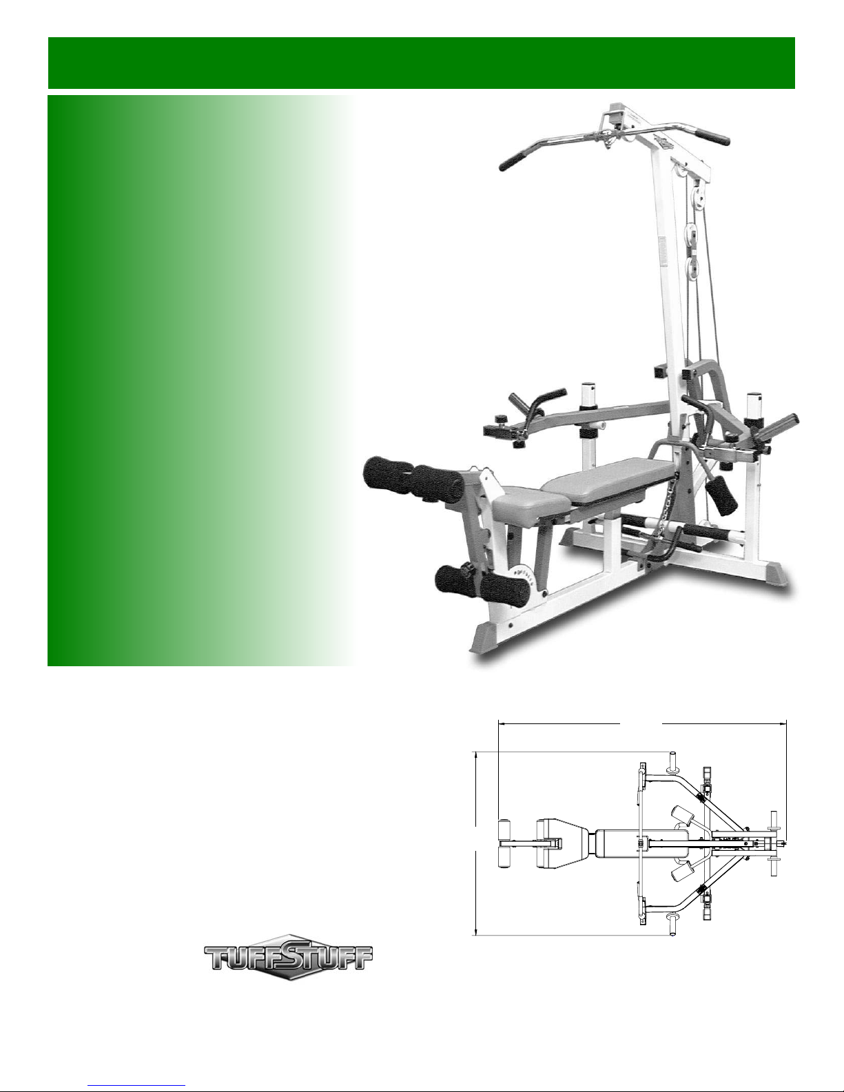
BRT-1
“The Brute” Plate Loaded
Home Gym
Revision Date 02-05-02
99”
63”
America’s Premium Exercise Equipment
© 2003 TASK INDUSTRIES, INC.
L 99” W 63” H 83”
-
Page 2
Introduction
N
About the Plate Loaded Home Gym (BRT-1)
Congratulations on your new purchase of the “The Brute” Plate
Loaded Home Gym (BRT-1). This gym is capable of a variety of
different exercises, as well as, smooth and user-friendly adjustment
features. In addition, this gym has been designed to meet the
needs and performance requirements for a suitable home exercise
machine. We hope you are completely satisfied with this product
and wish you many years of enjoyment.
Tuff Stuff Equipment
This Tuffstuff product has been built to precise quality standards
and has been carefully packaged to ensure that damage will not
occur during shipment.
indicating final inspection has been conducted by our line foreman,
is an expression of our confidence in the completeness, the
materials, and workmanship of this product.
The Home Lifetime Warranty and signature
Warranty
SEE A COPY OF WARRANTY ON BACK PAGE.
Registration Card
To avoid unnecessary delays in warranty service and to insure that
a permanent record of your purchase is on file with our factory, be
sure to complete the warranty registration card and send it to Task
Industries today.
Specifications
1. Maximum Wt. Capacity - 200 Lbs.
2. Total Machine Weight - 350 Lbs.
3. Footprint (LWH) - See Front Cover
About the Icons
The icons displayed in this Owner’s Manual are used to facilitate
the correct assembly and safe use of this Product, as-well-as to
prevent injury to yourself or anyone else.
Note provides information necessary to properly
complete a procedure or information which will
NOTE:
CAUTION
LOOSELY FASTEN
FULLY FASTE
make the procedure easier to understand.
Caution indicates a potentially hazardous situation, which, if not avoided, may result in minor or
moderate injury. It may also be used to alert
against unsafe practices.
Loosely Fasten provides a instruction to loosely
fasten (ex: hand tighten) a hardware assembly
only. This instruction is intended for the alignment
of hardware components during the assembly
process.
Fully Fasten provides a instruction to fully fasten
(ex: completely tighten) a hardware assembly.
Prior to the Assembly of the BRT-1
1. We advise you to consult your local Tuff Stuff retailer if you
should have a question or problem regarding the proper
assembly of this Home Gym.
2. Consider the complete surface area of the BRT-1. Use the
overhead view on the front page for designing your layout before
assembling. Once the BRT-1 has been fully assembled it will be
heavy and difficult to move, therefore you should assemble the it
in the area where it is to be used upon completion.
3. It is strongly recommended that another person assist you with
the assembly of this unit.
4. Neatly organize and identify all parts according to the Parts List
on page 21 and the Exploded View Diagram on fold-out page 22.
Tool Requirements
1. One 9/16” combination wrench
2. One 3/4” combination wrench
3. One 7/8” combination wrench
4. One 1/2” combination wrench
5. Two 7/16” combination wrenches
6. One ratchet
7. One 9/16” socket
8. One 3/4” socket
9. One 3/8” drive extension
10. One rubber mallet
11. Long-Reach Needle-Nose Pliers
12. Windex or household glass cleaner
13. Multi-purpose grease
14. Measuring tape
15. Utility knife
Assembly Notes
1. Read and follow each step of this Assembly Instruction Manual in
sequence. Do not skip ahead, as it will result in an improper
assembly or in having to disassemble parts later.
2. During the assembly of this unit you will be instructed to leave
some Hex Head Cap Screws loosely fastened. Naturally, they
will be fully fastened later in the assembly process. This is done
to prevent any difficulty with alignment of some parts during this
assembly.
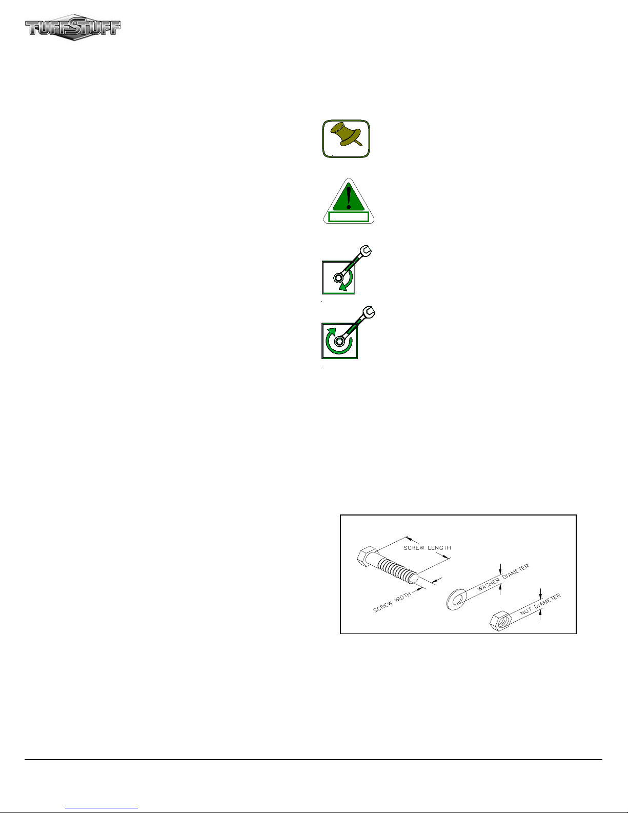
Hardware Measurement Diagram
Note: Due to continuing product improvements, specifications and designs are subject to change
without notice.
Even though we have prepared this manual with extreme care, neither the publisher nor the author
can accept responsibility for any errors in, or omission from, the information given.
1
BRT-1 “The Brute” Plate Loaded Home Gym
Page 3
Safety Precautions
S afety First
Regardless of how enthusiastic you may be about getting on
your equipment and exercising, take the time to ensure that
your safety is not jeopardized. A moment’s lack of attention
can result in an accident, as can failure to observe certain
simple safety precautions.
1. Read, study and understand the Owner’s Manual and all
the warning labels on this product. Furthermore, it is
recommended to familiarize yourself and others with the
proper operation and workout recommendations for this
Tuff Stuff product prior to use. Some of this information
can be obtained in this Owner’s Manual, as-well-as from
your local Tuff Stuff retailer.
2. It is imperative that you retain this Owner’s Manual and be
sure all warning labels are legible and intact. Replacement
Owner’s Manuals and labels are available from your local
Tuff Stuff retailer.
3. Consult with your physician before beginning any exercise
program.
4. Use proper discretion when children are present.
Weight Plates
CAUTION
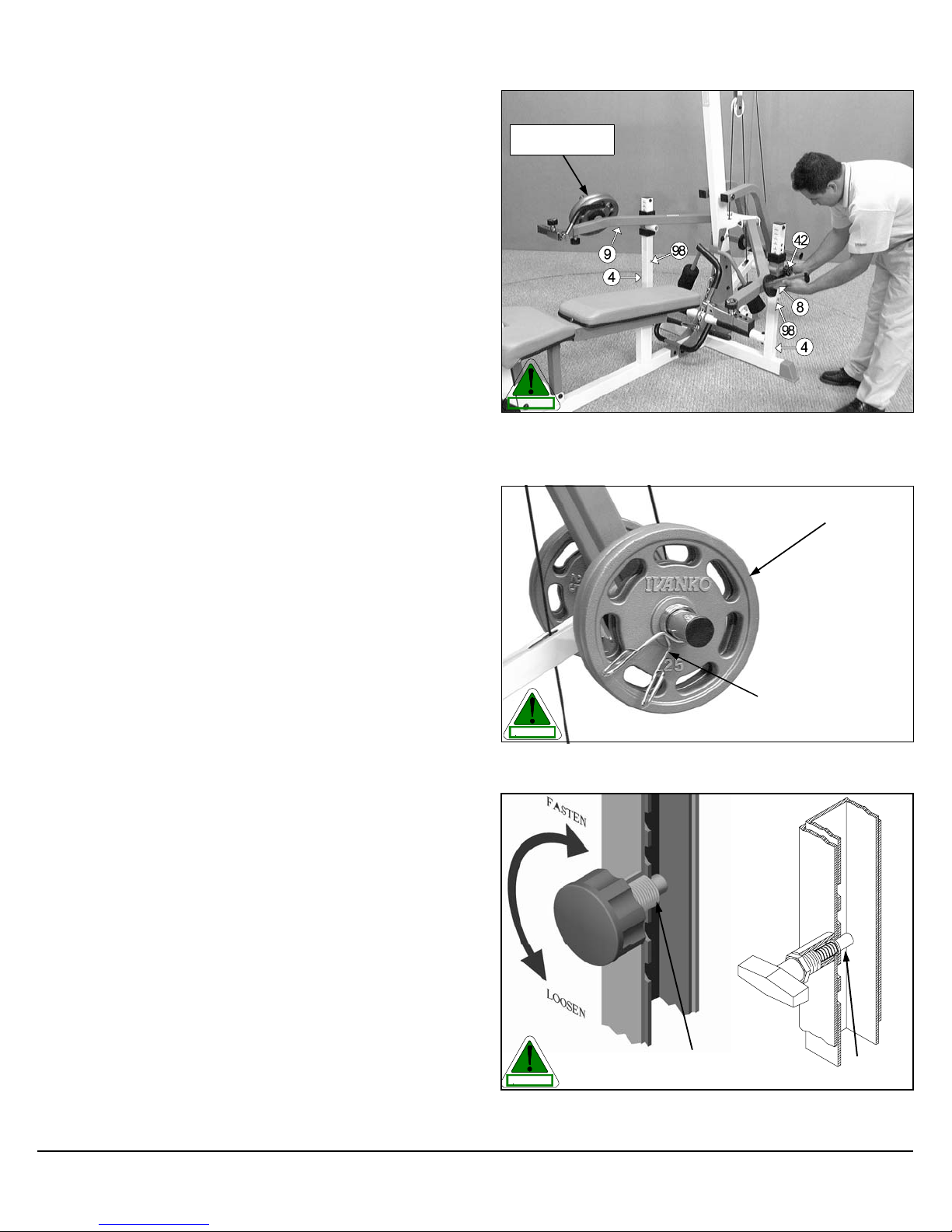
Fig. 1 Caution: Remove weight(s) on the Press Arms (#8, #9) before
releasing Turn/Pull Pin (#42) for any kind of height adjustments. Use the
Ring-Grip Self-Locking Pins (#98) at all times in case of accidental releasing of the Turn/Pull Pins (#42).
Olympic Weight
Plates
5. Frayed or worn cables can be dangerous and may cause
injury. Periodically check these cables for any indication of
wear.
6. Keep hands, limbs, loose clothing and long hair well out of
the way of moving parts.
7. Do not attempt to lift more weight than you can control
safely.
8. Inspect the Unit for any sign of wear on parts, hardware
becoming loose or cracks on welds. If a problem is found
do not use or allow the machine to be used until the
defective part is repaired or replaced.
9. Remove weight(s) on the Press Arms (#8, #9) before releasing Turn/Pull Pin (#42) for any kind of height adjustments. Use the Ring-Grip Self-Locking Pin (#98) at all
times to prevent the Press Arms (#8, #9) from falling beyond this point in case of accidental releasing of the Turn/
Pull Pins (#42). Refer to Fig. 1 for further illustration of this
instruction.
10.Secure the weight plates using collars to prevent the
weight plates from falling off the weight prongs of the Car-
riage (#10). Refer to Fig. 2 for further illustration of this
instruction.
Olympic Weight
Collar
CAUTION
Fig. 2 Caution: Use collars to prevent the weight plates from falling off
the weight prongs of the Carriage (#10)
11.Pay special attention to the Turn/Pull Pins w/Knob (#42)
and the Push Pull Pins (#43). Be sure they are fully
engaged into the selected holes of their corresponding assemblies. Refer to Fig. 3 for further illustration of this instruction.
BRT-1 “The Brute” Plate Loaded Home Gym
Turn/Pull Pin w/Knob
CAUTION
Fig. 3 Caution: Check the Turn/Pull Pins w/Knob (#42) and the
Push Pull Pins (#43) to be fully engaged into the selected holes of their
corresponding assemblies.
Fully Engaged
Push Pull Pin
Fully Engaged
2
Page 4
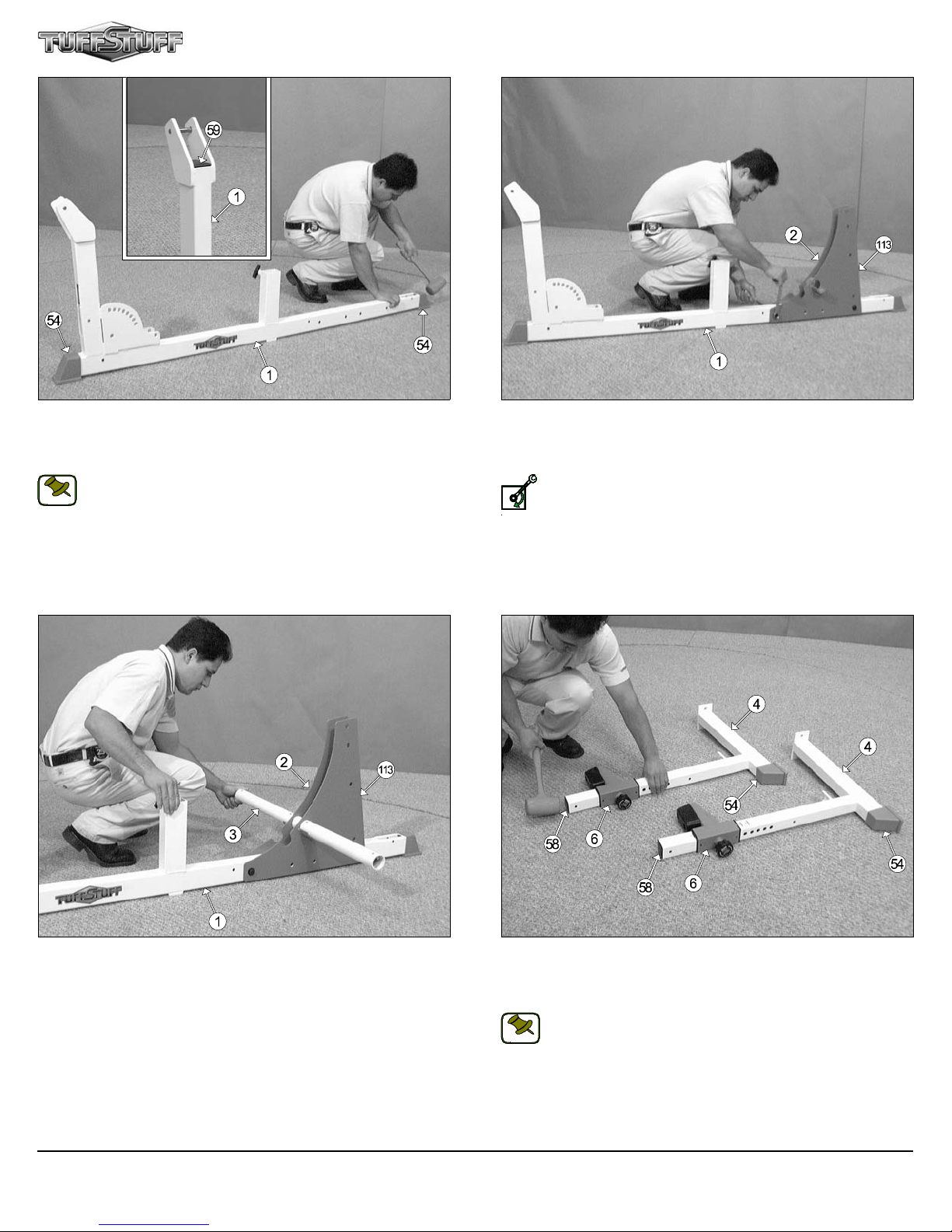
FIG. 4 Using a rubber mallet, insert two Plastic Insert Caps w/Groove 3
x 2 (#54) onto the bottom tube-ends of the Base Frame (#1). Next, insert
one Plastic Insert Cap 2 x 3 (#59) into the top tube-end of the Base
Frame (#1).
Note: When positioning the Base Frame (#1) consider the
complete area surface of the BRT-1. Use the overhead view on
NOTE:
the cover page for designing your layout before assembling.
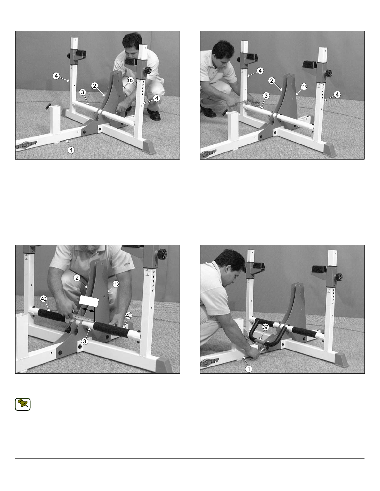
FIG. 5 Affix the Left and Right Triangular Reinforcement Plates (#2,
#113) to the Base Frame (#1), in the position as shown above, and se-
cure them into place using two Hex Head Cap Screws 1/2-13 X 3 1/4
(#69), four Flat Washers SAE 1/2” (#68), and two Nylon Insert Lock Nuts
1/2-13 (#74).
Loosely Fasten: Do not completely fasten this hardware assembly
at this time, as it will be completely fastened later in the assembly
LOOSELY FASTEN
process.
FIG. 6 Insert the Foot Support Tube (#3) half way through the receptacle of the two Triangular Reinforcement Plates (#2, #113), as shown
above.
3
FIG. 7 Locate the two Stabilizers (#4), and using a rubber mallet, insert two Plastic End Caps w/Groove 3 X 2 (#54) onto the bottom tubeends. Next, insert two Plastic Insert Caps 2” Sq. (#58) into the top tubeends of the Stabilizers (#4).
Note: The Press Arm Holders (#6) have been assembled to the
Stabilizers (#4).
NOTE:
BRT-1 “The Brute” Plate Loaded Home Gym
Page 5
Owner’s Manual: Assembly Instructions
FIG. 8 Affix the two Stabilizers (#4) to the Triangular Reinforcement
Plates (#2, #113) and the Base Frame (#1), in the position as shown
above, and secure them into place using two Hex Head Cap Screws 1/213 X 4 (#71), four Flat Washers SAE 1/2” (#68), and two Nylon Insert Lock
Nuts 1/2-13 (#74).
3 3/8”
FIG. 9 Secure the Foot Support Tube (#3) to the Triangular Rein-
forcement Plates (#2, #113), and the two Stabilizers (#4) using four Hex
Head Cap Screws 3/8-16 X 2 3/4 (#80), eight Flat Washers SAE
3/8” (#84), and four Nylon Insert Jam Lock Nuts 3/8-16 (#85).
FIG. 10 Remove the backing of the two Safety Anti-Slip Tape 4 X 10
(#40) strips. Next, attach the two Safety Anti-Slip Tape 4 X 10 (#40) to the
Foot Support Tube (#3), in the position as shown above.
Note: To facilitate the alignment of the strips across the Foot sup-
port Tube (#3), use a measuring tape. The measurement from the
NOTE:
edge of the Triangular Reinforcement Plate (#2, or #113) to the
inner edge of the Safety Anti-Slip Tape (#40), as picture above,
should be about 3 3/8”
BRT-1 “The Brute” Plate Loaded Home Gym
FIG. 11 Mount the Base Frame Handles (#37) to the Base Frame (#1)
and secure them into place using one Hex Head Cap Screw 3/8-16 X 2
3/4 (#80), two Flat Washers SAE 3/8” (#84), and one Nylon Insert Jam
Lock Nut 3/8-16 (#85).
4
Page 6
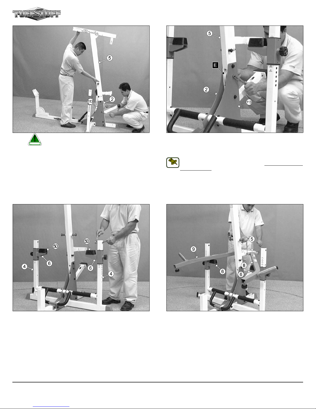
FIG. 12 Caution: It is strongly recommended to use another per-
son in assisting with this assembly.
CAUTION
Insert the Main Frame (#5) between the two Triangular Reinforcement
Plates (#2, #113), in the position as shown above. Next, secure the Main
Frame (#5) to the Triangular Reinforcement Plates (#2, #113) using
three Hex Head Cap Screws 1/2-13 X 3 1/4 (#69), six Flat Washers SAE
1/2” (#68), and three Nylon Insert Lock Nuts 1/2-13 (#74).
FIG. 13 Insert a Nylon Pulley 4 1/2 Rd. (#64-Labeled E) into the pulley
bracket located on the Main Frame (#5) and secure it into place using one
Hex Head Cap Screw 3/8-16 X 3 (#81), two Flat Washers SAE 3/8” (#84),
and one Nylon Insert Lock Nut 3/8-16 (#83).
Note: The black boxed letter pointing to the pulleys are used
throughout this manual as reference to the Cable Mapping Dia-
NOTE:
gram on page 20. These black boxed letters will be primarily used
for locating certain pulleys during the cable routing process beginning with Fig. 13.
FIG. 14 Confine the Arm Holders (#6) within the Stabilizer’s (#4) tubes
using two Hex Head Cap Screws 3/8-16 X 2 1/2 (#79), and two Nylon Insert Jam Lock Nuts 3/8-16 (#85).
5
FIG. 15 Rest the Right Press Arm (#9) on the corresponding Arm
Holder (#6) and affix it to the Main Frame (#5) using one Hex Head Cap
Screw 1/2-13 X 5 1/2 (#73), two Flat Washers SAE 1/2” (#68), and one
Nylon Insert Jam Lock Nut 1/2-13 (#75). Repeat the same procedure for
the Left Press Arm (#8).
BRT-1 “The Brute” Plate Loaded Home Gym
Page 7
Owner’s Manual: Assembly Instructions
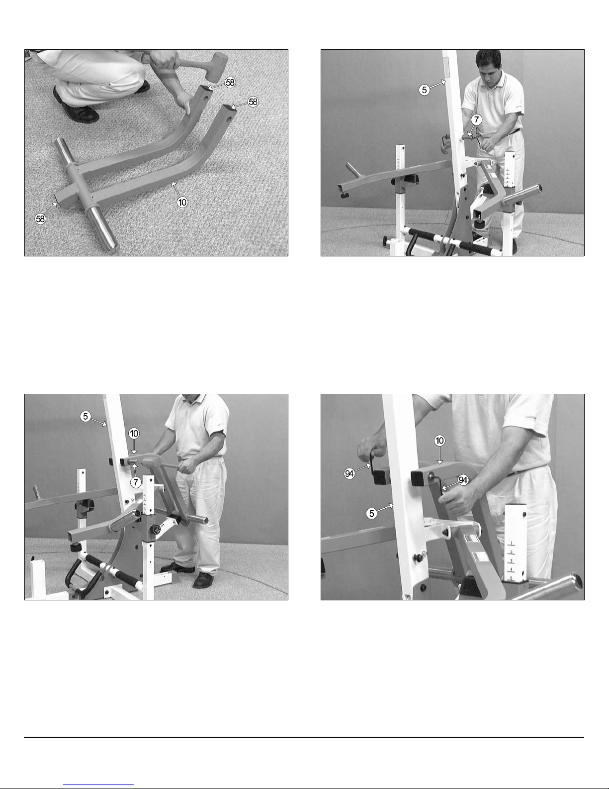
FIG. 16 Using a rubber mallet, insert three Plastic Insert Caps 2” Sq.
(#58) into the tube-ends of the Weight Carriage (#10).
FIG. 17 Using the two supplied Hex Keys 7/32” (#74), remove the Pivot
Axle 1 X 8 1/8 (#7) from the Main Frame (#5).
FIG. 18 Attach the Weight Carriage (#10) to the Main Frame (#5), in
the position as shown above. Next, using a rubber mallet, insert the Pivot
Axle 1 X 8 1/8 (#7) through the holes of the Weight Carriage (#10) and
the receptacle of the Main Frame (#5) until it is flush with both sides of the
Weight Carriage (#10).
BRT-1 “The Brute” Plate Loaded Home Gym
FIG. 19 Secure the Weight Carriage (#10) to the Pivot Axle (#7) using
two Chrome Washers 3/8 X 1 1/2 (#95), two Split Lock Washers
3/8” (#97), and two Button Socket Cap Screws 3/8-16 X 1 (#96). Use the
two supplied Hex Keys 7/32” (#94) to fasten this assembly properly.
6
Page 8
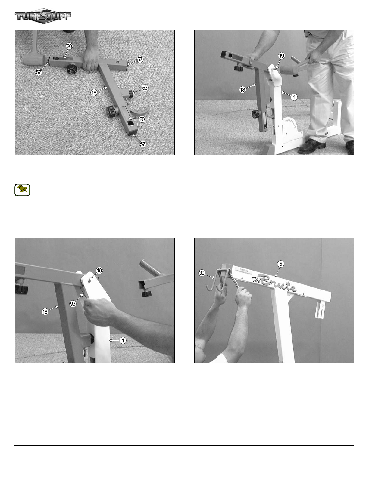
FIG. 20 Using a rubber mallet, insert three Plastic Insert Caps 1 3/4” Sq.
(#57) into the tube-ends of the Leg Extension Arm (#18). Next, attach
the Rubber Bumper 3/8 X 1 1/2 (#53) to the Leg Extension Arm (#18) using one Hex Head Cap Screw 3/8-16 X 1 1/4 (#76).
Note: The Adjustable Foot Roll Tubes (#20) have been assembled to the Leg Extension Arm (#18).
NOTE:
FIG. 21 Affix the Leg Extension Arm (#18), in the position as shown
above, to the Base Frame (#1) and secure it into place by inserting the
Leg Extension Axle 1/2 X 2 3/4 (#19) through the Base Frame (#1) hole
and the Leg Extension Arm (#18) receptacle until it becomes flush with
both sides of the Base Frame (#19).
FIG. 22 Secure the Leg Extension Axle 1/2 X 2 3/4 (#19) to the Base
Frame (#1) using two Set Screws 1/4-20 X 3/8 (#41). Use the supplied
Hex Key 1/8” (#93) to fasten these Set Screws.
7
FIG. 23 Attach the Lat Bar Holder (#30), in the position as shown
above, to the Main Frame (#5) and secure it into place using one Hex
Head Cap Screw 3/8-16 X 2 3/4 (#80), two Flat Washers SAE 3/8” (#84),
and one Nylon Insert Jam Lock Nut 3/8-16 (#85).
BRT-1 “The Brute” Plate Loaded Home Gym
Page 9

Owner’s Manual: Assembly Instructions
FIG. 24 Using a rubber mallet, insert a Plastic Insert Cap 2 X 3 (#59)
into the tube-end of the Main Frame (#5). Next, assemble the Adjust-
able Pulley Bracket (#34) to the Main Frame (#5), in the position as
shown above, and secure it into place using a Flat Washer SAE
1/2” (#68), and a Nylon Insert Lock Nut 1/2-13 (#74).
Loosely Fasten: Do not completely fasten this hardware assembly
at this time, as it will be completely fastened later in the assembly
process.
LOOSELY FASTEN
FIG. 25 Insert a Nylon Pulley 4 1/2 Rd. (#64-Labeled A) into the pulley
bracket located on the Main Frame (#5) and secure it into place using one
Hex Head Cap Screw 3/8-16 X 2 1/2 (#79), two Flat Washers SAE
3/8” (#84), and one Nylon Insert Jam Lock Nut 3/8-16 (#85).
Begin routing the Lat Cable (#31) up and over the Nylon Pulley
4 1/2 Rd (#64-Labeled A) and into the tube of the Main Frame (#5).
Then, pull the Lat Cable (#31) down through the opening at the bottom of
the Main Frame (#5).
Note: Refer to the Cable Mapping Diagram on page 20 for further
detailed illustration of the Lat Cable (#31) routing.
NOTE:
FIG. 26 Insert a Nylon Pulley 4 1/2 Rd. (#64-Labeled B) into the pulley
bracket located at the bottom of the Main Frame (#5) and secure it into
place using one Hex Head Cap Screw 3/8-16 X 2 1/2 (#79), two Flat
Washers SAE 3/8” (#84), and one Nylon Insert Jam Lock Nut 3/8-16
(#85).
Note: Refer to the Cable Mapping Diagram on page 20 for further
detailed illustration of the Lat Cable (#31) routing.
NOTE:
BRT-1 “The Brute” Plate Loaded Home Gym
FIG. 27 Attach two Nylon Pulleys 4 1/2 Rd. (#64-Labeled C, F), in the
position as shown above, to the Closed-end Adj. Double Pulley Bracket
(#33) and secure them into place using two Hex Head Cap Screws 3/8-16
X 1 3/4 (#77), four Flat Washers SAE 3/8” (#84), and two Nylon Insert
Jam Lock Nuts 3/8-16 (#85).
Note: The four holes on the Closed-end Adj. Double Pulley
Bracket (#33) are used to adjust the cable tension once the cable
NOTE:
routing has been completed.
8
Page 10

FIG. 28 Route the Lat Cable (#31) through the Closed-end Adj. Dou-
ble Pulley Bracket (#33) and under the Nylon Pulley 4 1/2 Rd. (#64-
Labeled C).
FIG. 29 Next, route the Lat Cable (#31) up into the Adjustable Pulley
Bracket (#34). Then, insert a Nylon Pulley 4 1/2 Rd. (#64-Labeled D) into
the Adjustable Pulley Bracket (#34) and secure it into place using one
Hex Head Cap Screw 3/8-16 X 2 (#78), two Flat Washers SAE 3/8” (#84),
and one Nylon Insert Jam Lock Nut 3/8-16 (#85).
Loosely Fasten: Do not completely fasten this hardware assembly
at this time, as it will be completely fastened later in the assembly
process.
LOOSELY FASTEN
Note: Refer to the Cable Mapping Diagram on page 20 for further
detailed illustration of the Lat Cable (#31) routing.
NOTE:
FIG. 30 Secure the looped end of the Lat Cable (#31) to the bracket of
the Weight Carriage (#10) using one Shoulder Bolt 3/8 X 3/4 (#86), and
one Nylon Insert Lock Nut 5/16-18 (#99).
9
FIG. 31 Next, slide a Rubber Bumper Washer (#101) onto each of the
weight prongs of the Weight Carriage (#10).
Note: To facilitate the insertion of these Rubber Bumper Washers
(#101), use Windex or household glass cleaner.
NOTE:
BRT-1 “The Brute” Plate Loaded Home Gym
Page 11

Owner’s Manual: Assembly Instructions
FIG. 32 Begin the routing of the Leg Extension Cable (#32) under the
Nylon Pulley 4 1/2 Rd. (#64-Labeled E), then up and through the opening
on the Main Frame (#5).
Note: Refer to the Cable Mapping Diagram on page 20 for further
detailed illustration of the Leg Extension Cable (#32) routing.
NOTE:
FIG. 33 Next, route the Leg Extension Cable (#32) up and over the Ny-
lon Pulley 4 1/2 Rd. (#64-Labeled F).
Note: Refer to the Cable Mapping Diagram on page 20 for further
detailed illustration of the Leg Extension Cable (#32) routing.
NOTE:
Top View
FIG. 34 Route the Leg Extension Cable (#32) down passing through
the opening located on the Main Frame (#5). Next, route the cable into
the opening on the Base Frame (#1). Then, insert a Nylon Pulley 4 1/2
Rd. (#64-Labeled G) into the pulley bracket of the Base Frame (#1) and
secure it into place using one Hex Head Cap Screw 3/8-16 X 2 1/2 (#79),
two Flat Washers SAE 3/8” (#84), and one Nylon Insert Jam Lock Nut 3/816 (#85).
Note: Refer to the Cable Mapping Diagram on page 20 for further
detailed illustration of the Leg Extension Cable (#32) routing.
NOTE:
BRT-1 “The Brute” Plate Loaded Home Gym
FIG. 35 Continue routing the Leg Extension Cable (#32) through the
tube of the Base Frame (#1). Then, pull the Cable up through the opening located at the top of the Base Frame (#1). Using Long-Reach Needle-Nose Pliers may facilitate pulling out the cable.
Note: Refer to the Cable Mapping Diagram on page 20 for further
detailed illustration of the Leg Extension Cable (#32) routing.
NOTE:
10
Page 12

FIG. 36 Locate a Nylon Pulley 3 1/2 (#65), and insert it into the hidden
pulley bracket located on the Base Frame (#1), as illustrated above.
FIG. 37 Secure the Nylon Pulley 3 1/2 Rd. (#65-Labeled H) into place
using one Hex Head Cap Screw 3/8-16 X 2 1/2 (#79), two Flat Washers
SAE 3/8” (#84), and one Nylon Insert Jam Lock Nut 3/8-16 (#85). Be sure
the cable is routed properly into the pulleys groove following the path as illustrated with the arrows .
Note: Refer to Fig D on page 20 for further clarification of this assembly.
NOTE:
FIG. 38 Next, insert a Nylon Pulley 3 1/2 Rd. (#65-Labeled I) into the
pulley bracket located in front of the Base Frame (#1) and secure it into
place using one Hex Head Cap Screw 3/8-16 X 2 1/2 (#79), two Flat
Washers SAE 3/8” (#84), and one Nylon Insert Jam Lock Nut 3/8-16
(#85). Be sure the cable is routed properly into the pulleys groove following the path as illustrated with the arrows .
Note: Refer to Fig D on page 20 for further clarification of this assembly.
NOTE:
11
FIG. 39 Route the Leg Extension Cable (#32) to the Leg Extension
Arm (#18) following the path illustrated with the arrows.
Note: Refer to the Cable Mapping Diagram on page 20 for further
detailed illustration of the Leg Extension Cable (#32) routing.
NOTE:
BRT-1 “The Brute” Plate Loaded Home Gym
Page 13

Owner’s Manual: Assembly Instructions
FIG. 40 Confine the Leg Extension Cable (#32) within the strap bracket
welded to the Leg Extension Arm (#18) using a Shoulder Bolt 3/8 X 3/4
(#86), and a Nylon Insert Lock Nut 5/16-18 (#99). Use the supplied Hex
Key 3/16” (#92) and a 1/2” combination wrench to fasten this assembly
properly.
Note: Refer to Fig C on page 19 for further clarification of this assembly.
NOTE:
FIG. 41 Affix the Seat Frame Adjustable Pivot Arm (#12), in the posi-
tion as shown above, to the Base Frame (#1) and secure it into place using one Hex Head Cap Screw 1/2-13 X 3 1/4 (#69), two Flat Washers SAE
1/2” (#68), and one Nylon Insert Jam Lock Nut 1/2-13 (#75).
FIG. 42 Next, affix the Seat Frame Pivot Arm (#11), in the position as
shown above, to the Base Frame (#1) and secure it into place using one
Hex Head Cap Screw 1/2-13 X 3 1/4 (#69), two Flat Washers SAE
1/2” (#68), and one Nylon Insert Jam Lock Nut 1/2-13 (#75).
BRT-1 “The Brute” Plate Loaded Home Gym
FIG. 43 Mount the Channel Seat Frame (#13), in the position as shown
above, onto the Seat Frame Pivot Arms (#11, #12) and secure it into
place using two Hex Head Cap Screws 1/2-13 X 4 (#71), four Flat Washers SAE 1/2” (#68), and two Nylon Insert Jam Lock Nuts 1/2-13 (#75).
12
Page 14

FIG. 44 Attach the Seat Elevation Bracket (#14), in the position as
shown above, to the Channel Seat Frame (#13) and secure it into place
using one Hex Head Cap Screw 1/2-13 X 4 1/4 (#72), two Flat Washers
SAE 1/2” (#68), and one Nylon Insert Jam Lock Nut 1/2-13 (#75).
FIG. 45 Insert the Incline Bench Elevation Tube (#15), in the position
as shown above, into the receptacle located on the Base Frame (#1). Be
sure to disengage the Push Pull Pin 1/2 X 3 1/2 (#43) as you begin inserting the Incline Bench Elevation Tube (#15) into the Base Frame (#1).
Confine the Incline Bench Elevation Tube (#15) within the
Base Frame (#1) receptacle using the Shoulder Bolt 3/8 X 3/4 (#86). Use
the supplied Hex Hey 3/16” (#92) to fasten the Shoulder Bolt 3/8 X 3/4
(#86).
FIG. 46 Locate the left and right Incline Bench Channels (#16, #17)
and apply a thin coat of grease to the inside walls of the Channels.
13
FIG. 47 Connect the left and right Incline Bench Channels (#16, #17),
in the position as shown above, to the Channel Seat Frame (#13) and the
Incline Bench Elevation Tube (#15).
BRT-1 “The Brute” Plate Loaded Home Gym
Page 15

Owner’s Manual: Assembly Instructions
FIG. 48 Attach the two Metal Hinges (#44) to the axle of the Channel
Seat Frame (#13). Be sure to position the Metal Hinges (#44) as shown
above.
FIG. 49 Place the Seat and Back Pad Cover (#46) on top of the Incline
Bench Channels (#16, #17) and the Channel Seat Frame (#13).
The picture depicts position of the Hex Head Cap Screws 3/816 X 1 1/4 (#76) passing through the Metal Hinges (#44) and the Seat
and Back Pad Cover (#46).
FIG.50 Attach the Seat Pad (#24) to the Cover (#46) and the Metal
Hinges (#44) using the previously described Hex Head Cap Screws 3/816 X 1 1/4 (#76), and two Flat Washers SAE 3/8” (#84).
BRT-1 “The Brute” Plate Loaded Home Gym
FIG. 51 Attach the Flat Incline Pad (#23), in the position as shown
above, to the Cover (#46) and the left and right Incline Bench Channels
(#16, #17) using four Hex Head Cap Screws 3/8-16 X 3 1/2 (#82), and
four Flat Washers SAE 3/8” (#84).
14
Page 16

FIG. 52 Insert two Foam Foot Rolls 1 X 4 X 7 (#61) onto the tube-ends
of the Leg Hold Down Frame (#22). Next, using a rubber mallet, insert
two Foot Roll Plastic End Caps 1” (#62) into the tube-ends of the Leg
Hold Down Frame (#22).
FIG. 53 Affix the Leg Hold Down Frame (#22), in the position as shown
above, to the Main Frame (#1) using one Hex Head Cap Screw 1/2-13 X
3 1/2 (#70), two Flat Washers SAE 1/2” (#68), two Nylon Flat Washers
1/2” (#66), and one Nylon Insert Jam Lock Nut 1/2-13 (#75).
FIG. 54 Slide a Rubber Bumper Washer (#101) onto each of the weight
prongs of the Press Arms (#8, #9).
Note: To facilitate the insertion of these Rubber Bumper Washers
(#101), use Windex or household glass cleaner.
NOTE:
Locate the left and right Extension Arm Tubes (#25, #26) and insert
them into the receptacles of the left and right Press Arms (#8, #9). Be
sure to disengage the Turn/Pull Pin w/Knob (#42) as you insert the Exten-
sion Arm Tubes (#25, #26) into the receptacles of the left and right Press
Arms (#8, #9).
15
FIG. 55 Locate the assembled Press Arm Handles (#27) and, using a
rubber mallet, insert two Plastic Insert Caps 1 3/4” Sq. (#57) into the tubeends of the left and right Handle Housing Tubes (#28, #29).
BRT-1 “The Brute” Plate Loaded Home Gym
Page 17

Owner’s Manual: Assembly Instructions
FIG. 56 Insert the left and right Handle Housing Tubes (#28, #29) into
the receptacles of the left and right Extension Arm Tubes (#25, #26).
Be sure to disengage the Turn/Pull Pin w/Knob (#42) as you insert the
Handle Housing Tubes (#28, #29) into the receptacles of the left and
right Extension Arm Tubes (#25, #26).
FIG. 57 Insert the two Foot Roll Tubes (#21) into the receptacles on
the two Adjustable Foot Roll Tube Housings (#20), as shown above.
FIG. 58 Next, insert one Foam Foot Roll 1 X 4 X 7 (#61), in the position
as shown above, onto each tube end of the two Foot Roll Tubes (#21).
BRT-1 “The Brute” Plate Loaded Home Gym
FIG. 59 Using a rubber mallet, insert one Foot Roll Plastic End Cap
1” (#62), in the position as shown above, into each tube end of the two
Foot Roll Tubes (#21).
16
Page 18

FIG. 60 Insert a Rubber Grip 1 x 6 1/4 (#51) over each one of the tube-
ends of the Low Row Bar 20” (#36), and the Lat Bar 48” (#35), as shown
above.
Note: To facilitate the insertion of these Rubber Grips, use Windex
or household glass cleaner.
NOTE:
FIG. 61 Next, attach a Snap Link (#90) to the Lat Cable (#31), in the po-
sition as shown above, and secure it into place using one Shoulder Bolt
3/8 X 3/4 (#86), and one Nylon Insert Lock Nut 5/16-18 (#99). Use the
supplied Hex Key 3/16” (#92) and a 1/2” combination wrench to fasten this
assembly properly.
Note: Refer to Fig A on page 19 for further illustration of this assembly.
NOTE:
Connect the Lat Bar (#35) to the Lat Cable (#31) using the Snap Link
(#90). Rest the Lat Bar (#35) onto the Lat Bar Holder (#30) when not in
use.
FIG. 62 Locate the Coil Chain 3/16 X 21 (#91), two Snap Links (#90)
and attach them to the Low Row Bar (#36) and the Leg Extension Cable
(#32), as shown above.
Rest the Low Row Bar (#36) onto the notch located on Triangular Rein-
forcement Plates when not in use.
17
FIG. 63 Insert a Ring-Grip Self-Locking Pin (#98) into the bottom hole of
the two Stabilizers (#4), as shown above. Use these Ring-Grip SelfLocking Pins (#98) at all times to prevent the Press Arms (#8, #9) from
falling beyond this point in case of accidental releasing of the Turn/Pull
Pins (#42)
BRT-1 “The Brute” Plate Loaded Home Gym
Page 19

BRT-1 CABLE ADJUSTMENT DIAGRAM
It is imperative that you maintain the cables properly adjustment to ensure a safe and smooth operation.
Cables should be inspected and adjusted periodically to avoid any
slack in the cables which would, consequently, prevent any damage to the equipment or personal injury.
CAUTION
Minor Cable Adjustment
1. Loosen the hardware that holds the Nylon
Pulley (#64-Labeled D) to the Main Frame’s
(#5) pulley bracket.
2. Thread in or out the Nylon Insert Lock (#74)
to give the cable proper tension.
3. Re-tighten the hardware that holds the Nylon
Pulley (#64-Labeled D) to the Main Frame’s
(#5) pulley bracket to complete the cable
adjustment.
Major Cable Adjustment
1. Remove the hardware from the Nylon Pulley
(#64-Labeled F).
2. By interchanging the Nylon Pulley (#64Labeled F) to the next adjustment hole within
the Closed-end Adj. Double Pulley
Bracket (#33) it will make one inch cable ad-
justment.
3. Re-tighten the hardware for the Nylon Pulley
(#64-Labeled F) to complete the cable adjustment.
FULLY FASTEN
Fully Fasten: Proceed to Fully Fasten these
hardware assemblies and all of the previous assemblies that were left loosely fastened.
BRT-1 “The Brute” Plate Loaded Home Gym
18
Page 20

FIG. B
Note: Some parts have
been cut away for clarity.
NOTE:
CABLE MAPPING DIAGRAM
19
FIG. C
FIG. A
BRT-1 “The Brute” Plate Loaded Home Gym
Page 21

CABLE MAPPING DIAGRAM
Note: Some parts have
been cut away for clarity.
NOTE:
BRT-1 “The Brute” Plate Loaded Home Gym
FIG. D
20
Page 22

t
FOAM FOOT ROLL 1 X 4 X 7
NYLON PULLEY, WHITE 3 1/2
NYLON FLAT WASHER 1/2"
NYLON BALL 1 3/4 X 5/16
SNAP LINK
SPLIT LOCK WASHER B/O 3/8"
RING-GRIP SELF-LOCKING PIN
RUBBER BUMPER WASHER
DECAL-CAUTION 1 3/4 X 5-1/2
R
DECAL-ADJUST CABLE HERE
COLOR CHART
GRAY= SUB-ASSEMBLY PARTS
BLACK= HARDWARE
em No. Description Part No. Qty Item No. Description Part No. Qty
BASE FRAME UP745 1 58 PLASTIC INSERT CAP 2" SQ. 10-14 GA. BNH0012 5
1
2 TRIANGULAR REINFORCEMENT PLATE RIGHT UP843 1 59 PLASTIC INSERT CAP 2 X 3 11-14 GA BNH0052 2
FOOT SUPPORT UP747 1
3
4 STABILIZER UP748 2 61
5 MAIN FRAME UP749 1 62 FOOT ROLL PLASTIC END CAP 1" BNH0397 6
6 PRESS ARM HOLDER UP750 2 63 PLASTIC TUBE GUIDE W/LIP-TEETH 2 SQ X 1 BNH0379 4
7 PIVOT AXLE 1 X 8-1/8 UP751 1 64 NYLON PULLEY 4-1/2 RD. WHITE BNH0556 7
LEFT PRESS ARM UP752 1
8
RIGHT PRESS ARM UP753 1
9
10 WEIGHT CARRIAGE UP754 1 67 FLAT WASHER 1/2 X 7/8 X1/16 BNH0210 2
11 SEAT FRAME PIVOT ARM UP755 1 68 FLAT WASHER SAE B/O 1/2" BNH0238 31
12 SEAT FRAME ADJUSTABLE PIVOT ARM UP756 1 69 HEX HEAD CAP SCREW GR-5 B/O 1/2-13 X3-1/4 BNH0576 7
CHANNEL SEAT FRAME UP757 1
13
SEAT ELEVATION BRACKET UP758 1
14
15 INCLINE BENCH ELEVATION TUBE UP759 1 72 HEX HEAD CAP SCREW GR-5 B/O 1/2-13 X 4-1/4 BNH0291 1
16 LEFT INCLINE BENCH CHANNEL UP255 1 73 HEX HEAD CAP SCREW GR-5 B/O 1/2-13 X5-1/2 BNH0267 2
17 RIGHT INCLINE BENCH CHANNEL UP254 1 74 NYLON INSERT LOCK NUT B/O 1/2-13 BNH0212 8
LEG EXTENSION ARM UP760 1
18
PIVOT AXLE 1/2 X 2-3/4 UP373 1
19
20 ADJUSTABLE FOOT ROLL TUBE UP761 2 77 HEX HEAD CAP SCREW GR-5 B/O 3/8-16 X1-3/4 BNH0274 2
21 FOOT ROLL TUBE 1 X 16 UP053 2 78 HEX HEAD CAP SCREW GR-5 B/O 3/8-16 X 2 BNH0279 1
22 LEG HOLD DOWN FRAME UP762 1 79 HEX HEAD CAP SCREW GR-5 B/O 3/8-16 X2-1/2 BNH0276 7
23 BACK PAD UP256 1 80 HEX HEAD CAP SCREW GR-5 B/O 3/8-16 X 2-3/4 BNH0278 6
SEAT PAD UP763 1
24
25 LEFT EXTENSION ARM TUBE UP764 1 82 HEX HEAD CAP SCREW GR-5 B/O 3/8-16 X3-1/2 BNH0280 4
26 RIGHT EXTENSION ARM TUBE UP765 1 83 NYLON INSERT LOCK NUT B/O 3/8-16 BNH0214 1
27 PRESS ARM HANDLES UP766 2 84 FLAT WASHER SAE B/O 3/8" BNH0239 50
28 LEFT HANDLE HOUSING TUBE UP767 1 85 NYLON INSERT JAM LOCK NUT B/O 3/8-16 BNH0365 20
RIGHT HANDLE HOUSING TUBE UP768 1
29
30 LAT BAR HOLDER UP327 1 87 NYLON INSERT LOCK NUT B/O 1/4-20 BNH0213 2
31 LAT CABLE UP769 1 88 STRAP BRACKET #20 BNH0562 2
32 LEG EXTENSION CABLE UP770 1 89
33 CLOSED-END ADJ. DOUBLE PULLEY BRACKET UP689 1 90
ADJUSTABLE PULLEY BRACKET UP368 1
34
35 LAT BAR 48" BNH0295 1 92 HEX KEY 3/16" BNH0371 1
36 LOW ROW BAR 20" BNH0294 1 93 HEX KEY 1/8" BNH0767 1
37 BASE FRAME HANDLES UP774 1 94 HEX KEY 7/32" BNH0575 2
38 BRONZE BUSHING 1 X 1-1/4 X 3/4 X 1-1/2 X 1/8 BNH0527 4 95 CHROME WASHER 3/8 X 1 1/2 BNH1015 2
BRONZE BUSHING 1/2 X 5/8 X 1/2 X 7/8 X 1/8 BNH0528 12
39
SAFETY TAPE ANTI-SLIP 4 X 10 BNH1086 2
40
41 SOCKET SET SCREW ALLOY 1/4-20 X 3/8 BNH0772 2 98
42 TURNTURN/PULL PIN W/KNOB AND LOCK BNH0989 8 99 NYLON INSERT LOCK NUT B/O 5/16-18 BNH0215 4
43 PUSH PULL PIN 1/2 X 3-1/2 BNH0520 3 100 SUPER LUBE GREASE BNH0704 2
METAL HINGE BNH0046 2
44
RUBBER GRIP 1 ID X .125 X 10 BNH0968 4
45
46 SEAT AND BACK PAD COVER UP775 1 103 DECAL LARGE TUFFSTUFF LOGO BNH0360 2
47 HEX HEAD CAP SCREW GR-5 B/O 1/4-20 X 2 BNH1138 2 104 DECAL THE BRUTE 15 X 2 5/8 BNH0361 2
48 URETHANE BUMPER BNH0244 2 105 DECAL NUMBERS 1-9 BNH0341 2
FLAT PHILLIPS MACHINE SCREW 8-24 X 1/4 BNH0408 8
49
RUBBER BUMPER 2 1/2 X 4 3/4 X 2 BNH0496 3
50
51 RUBBER GRIP 1 X 6 1/4 BNH0296 4 108
52 FLANGED BEARING 1/2 X 1.253 X .386 BNH1081 4 109 DECAL-CAUTION LAT BAR HOLDE
53 RUBBER BUMPER 3/8 X 1-1/2 BNH0514 1 110
54 PLASTIC END CAP W/GROOVE 3 X 2 GREY BNH0134 4 111 DECAL-DANGER TIGHTEN THIS RET..., BNH0142 3
CHROME CAP 1 7/8" RD
55
56 PLASTIC END CAP 2" RD. BNH0001 2 113 TRIANGULAR REINFORCEMENT PLATE LEFT UP844 1
57 PLASTIC INSERT CAP 1-3/4" SQ. 10-14 GA. BNH0053 5
BRT-1 PARTS LIST
60
65
66
70
71
75
76
81
86
91
96
97
101
102
106
107
NH1016
112
PLASTIC INSERT CAP 1" RD. 10-12 GA. BNH0002 4
BNH0043 6
BNH1136 2
BNH0220 2
HEX HEAD CAP SCREW GR-5 B/O 1/2-13 X 3-1/2 BNH0263 1
HEX HEAD CAP SCREW GR-5 B/O 1/2-13 X 4 BNH0266 4
NYLON INSERT JAM LOCK NUT B/O 1/2-13 BNH0366 8
HEX HEAD CAP SCREW GR-5 B/O 3/8-16 X 1-1/4 BNH0273 5
HEX HEAD CAP SCREW GR-5 B/O 3/8-16 X 3 BNH0282 1
SHOULDER BOLT ALLOY 3/8 X 3/4 BNH0718 4
BNH0392 2
BNH0065 3
COIL CHAIN 3/16 X 21 BNH0017 1
BUTTON SOCKET CAP SCREW 3/8-16 X 1 BNH0115 2
BNH0658 2
BNH0647 2
BNH0933 4
SOCKET SET SCREW ALLOY 3/8-16 X 1/2 BNH0474 2
DECAL WARNING REMOVE WEIGHTS... BNH0370 2
DECAL-WARNING KEEP HANDS AND FINGERS..... BNH0620 2
BNH0126 1
BNH0140 1
BNH0789 2
EX HEAD CAP SCREW GR-5 B/O 3/8-16 X 1 1/2
NH0303
21
BRT-1 “The Brute” Plate Loaded Home Gym
Page 23

Adjustment Features
FIG. 64 Press Arms (#8, #9) Settings
Press Arms easily adjust to perform exercises:
Seated Mid Row
Flat Press
Incline Press
Decline Press
Shoulder Press
FIG. 65 Press Arms (#8, #9) Adjustments:
1. Remove weights on the Press Arms.
2. Grasp the Press Arm.
3. Turn counterclockwise then pull the Turn/Pull Pin (#42) to release the
Press Arm Holder (#6) from the Stabilizer (#4).
4. Adjust Press Arm and Press Arm Holder to the desired position
5. Release the Turn/Pull Pin (#42) and make sure it fully engages into the
selected hole of the Stabilizer (#4).
6. Complete the adjustment by turning the Turn/Pull Pin (#42) clockwise.
7. Repeat the same procedure for the other Press Arm.
Note: Use the Decal Numbers 1-9 (#105) as reference to ensure
that the Press Arms are on equal Adjustment Settings (same
NOTE:
height).
FIG. 66 Back Pad (#23) Settings:
♦ A used for Decline Position
♦ B used for Flat Position
♦ C, D used for Incline Positon
BRT-1 “The Brute” Plate Loaded Home Gym
FIG. 67 Back Pad (#23) Adjustment:
1. Grasp the Back Pad (#23).
2. Pull the Push Pull Pin 1/2 X 3 1/2 (#43).
3. Adjust the Back Pad (#23) to the desired position.
4. Release the Push Pull Pin 1/2 X 3 1/2 (#43) and make sure it fully engages into the selected hole of the Incline Bench Elevation Tube
(#15).
23
Page 24

Adjustment Features
FIG. 68 Seat / Back Pad Settings:
Illustration of the Seat / Back Pad gradual adjustment settings ranging
from Decline Position to Upright Position.
♦ Settings 1-2 used for Flat Position
♦ Settings 3-10 used for Incline Position
FIG. 69 Seat / Back Pad Adjustment:
1. Grasp the Seat Pad (#24).
2. Pull the Push Pull Pin 1/2 X 3 1/2 (#43).
3. Adjust the Seat / Back Pad to the desired position.
4. Release the Push Pull Pin 1/2 X 3 1/2 (#43) and make sure it fully engages into the selected hole of the Base Frame’s (#1) Bracket.
FIG. 70 Seat Pad (#24) Adjustment:
1. Grasp and raise the Seat Pad (#24).
2. Flip the Seat Elevation Bracket (#14) to upright position.
3. Rest the Seat Pad (#24) on top of the Seat Elevation Bracket (#14).
24
FIG. 71 Leg Hold Down Frame (#22) Adjustment:
1. Grasp the Leg Hold Down Frame (#22).
2. Pull the Push Pull Pin (#43).
3. Bring the Leg Hold Down Frame (#22) to horizontal position.
4. Release the Push Pull Pin (#43) and make sure it fully engages into the
hole of the Leg Hold Down Frame (#22).
Note: Bring the Leg Hold Down Frame (#22) to the lower position
when not in use.
NOTE:
BRT-1 “The Brute” Plate Loaded Home Gym
Page 25

Adjustment Features
FIG. 72 Press Arm Handles (#27) Settings:
Swivel Press Arm Handles (#27) help maintain perfect form throughout
performance of exercise.
FIG. 73 Extension Arm Tubes (#25, #26) settings:
Adjustable Extension Arms Gradual Range of Adjustments accommodate for various arm lengths.
FIG. 74 Handle Housing Tubes (#28, #29) Settings:
Adjustable Handle Housing Tubes Gradual Range of Adjustments accommodate for various body widths.
BRT-1 “The Brute” Plate Loaded Home Gym
FIG. 75 Foot Roll (#61) Settings:
Foot Rolls Gradual Range of Adjustments accommodate for individual leg
lengths.
25
Page 26

DO NOT DISCARD THIS MANUAL
HOME LIFETIME WARRANTY
TuffStuff products are warranted to the retail purchaser to be free from defects in materials and workmanship.
TuffStuff exclusive Home Lifetime Warranty coverage extends for the life of the product while owned by the
original retail purchaser, and used only in a home or residential setting unless otherwise noted in the owner’s
manual.
This warranty does not cover:
1. TuffStuff products sold for and used in a commercial or institutional setting.
2. Any damage, failure or loss caused by accident, misuse, neglect, abuse, improper assembly, improper
maintenance, or failure to follow instructions or warnings in the owner’s manual and warning labels
posted on the machine.
3. Use of products in a manner for which they were not designed.
4. Original product that is altered, or the use of replacement parts and components of another manufacturer other than TuffStuff.
Limitations:
The foregoing shall constitute the sole remedy of the purchaser and the sole liability of TuffStuff with regard to
warranty, whether express or implied by operation of law or otherwise, including but not limited to any implied
warranties of merchantability or fitness. TuffStuff shall in no event be liable for incidental or consequential
losses, damages or expenses in connection with exercise products. TuffStuff’s liability hereunder is expressly
limited to the repairs or replacements of warranted defective parts.
Procedures:
Warranty service will be performed at TuffStuff’s facility in Pomona, California. TuffStuff will have the option of
either repair or replacement at no charge for any defective product. Purchaser is responsible for installation of
repaired or replaced parts and all transportation and insurance costs on returned or replaced equipment to and
from TuffStuff’s facility in Pomona.
This warranty gives you specific legal rights and you may also have other rights, which may vary from state to
state. Effective July 1, 2004.
This warranty is the final, complete and exclusive agreement of the parties with respect to the quality or performance of the equipment
and no action for breach of this written warranty or any implied warranty shall be commenced more than one (1) year after the accrual
of the cause of action. No modification of this warranty or waiver of its terms shall be binding on either party unless approved in
writing by an authorized representative of the party. Contact TuffStuff at 1325 E. Franklin Avenue, Pomona, California 91766, before
returning any defective equipment.
Note: Retain your sales receipt and be sure to mail in the warranty registration card to insure that a
permanent record of your purchase is on file with the factory and to avoid unnecessary delays in
warranty service.
TASK INDUSTRIES, INC.
1325 E. Franklin Ave., Pomona, CA 91766
Ph: 909-629-1600 Fax: 909-629-4967
E-mail: service@tuffstuff.net Net: www.tuffstuff.net
 Loading...