

Page 1
ASSEMBLY INSTRUCTIONS
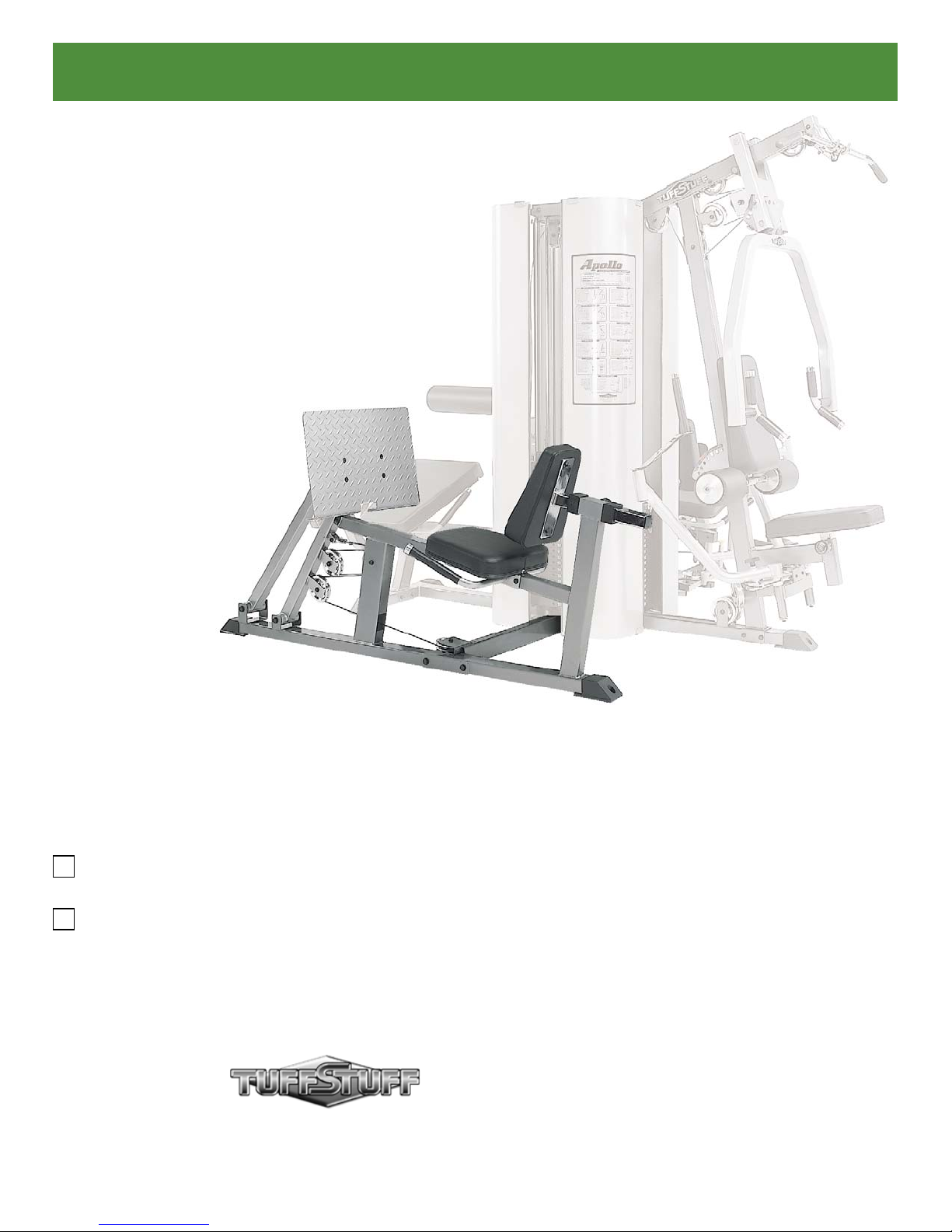
Apollo Modular Gym System
Leg Press Station
Standard
Deluxe
America’s Premier Exercise Equipment
Revision Date 08-23-05
Leg Press Station Rev0
Page 2
Introduction
A
bout the Leg Press Station
Congratulations on your new purchase of the Leg Press Station.
We hope you are completely satisfied with this product and wish
you many years of enjoyment.
T
uff Stuff Equipment
Every Tuffstuff product has been built to precise quality
standards and has been carefully packaged to ensure that damage
will not occur during shipment. The TuffStuff Warranty and signature
indicating final inspection has been conducted by our line foreman,
is an expression of our confidence in the completeness, the
materials, and workmanship of this product.
W
arranty
SEE A COPY OF WARRANTY ON BACK PAGE
R
egistration Card
To avoid unnecessary delays in warranty service and to insure
that a permanent record of your purchase is on file with our factory,
be sure to complete the warranty registration card and send it to
TuffStuff Fitness Equipment today.
Prior to the Assembly of the Leg Press Station
1. We advise you to consult your local Tuff Stuff retailer if you
should have a question or problem regarding the proper
assembly of this unit.
2. Neatly organize and identify all parts according to the Exploded
View Diagram on Fold-out Pg. 7 and the Parts List on Pg. 8.
Tool Requirements
1. One 9/16” combination wrench
2. One ratchet
3. One 9/16” socket
4. One rubber mallet
5. Multi-purpose grease
6. Measuring tape
7. Utility knife
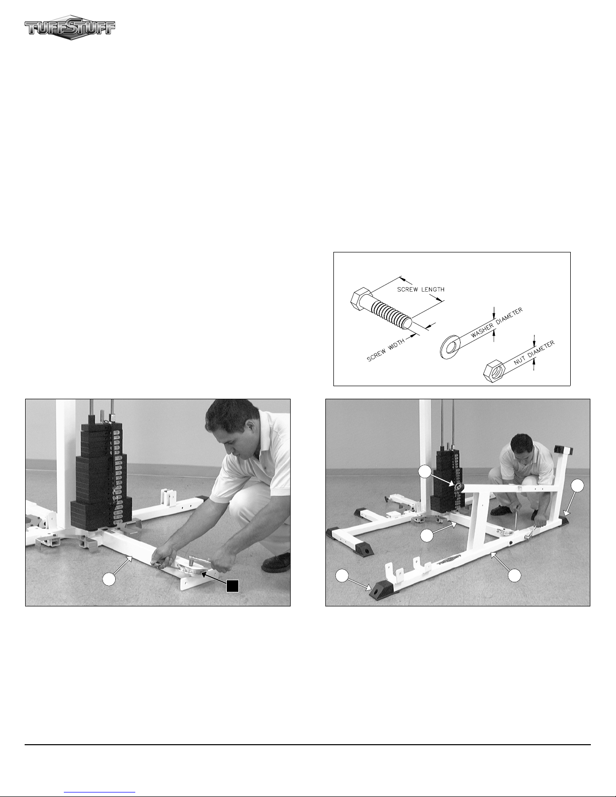
Hardware Measurement Diagram
Specifications
1. Maximum Wt. Capacity - 200 Lbs.
2. Total Machine Weight - 150 Lbs.
Note: Due to continuing product improvements, specifications and designs are subject to change
withou t notice.
46
D5
132
153
132
46
47
FIG. 1 Attach a Pulley 4 1/2” Rd. (#78-Labeled D5) to the Leg
Press Bottom Connector (#46) pulley bracket using one Hex Head
Cap Screw 3/8-16 X 1 3/4 (#101), two Flat Washers SAE 3/8” (#94),
and one Nylon Insert Jam Lock Nut 3/8-16 (#123).
1
FIG. 2 Using a rubber mallet, insert two Plastic End Caps 2 X 3
(#132) onto the tube-ends of the Leg Press Main Frame (#47). Next,
attach the Rubber Bumper 3/8 X 2 1/2 (#153) to the tube-end of the
Leg Press Main Frame (#47) using one Hex Head Cap Screw 3/8-16
X 1 1/2 (#100), and the Steel Bumper Washer 3/8” (#177).
Next, affix the Leg Press Main Frame (#47) to the Leg Press Bottom
Connector (#46) using two Hex Head Cap Screws 1/2-13 X 4 3/4
(#112), four Flat Washers SAE 1/2” (#93), and two Nylon Insert Lock
Nuts 1/2-13 (#124).
Leg Press Station
Page 3
Assembly Instructions
52
51
47
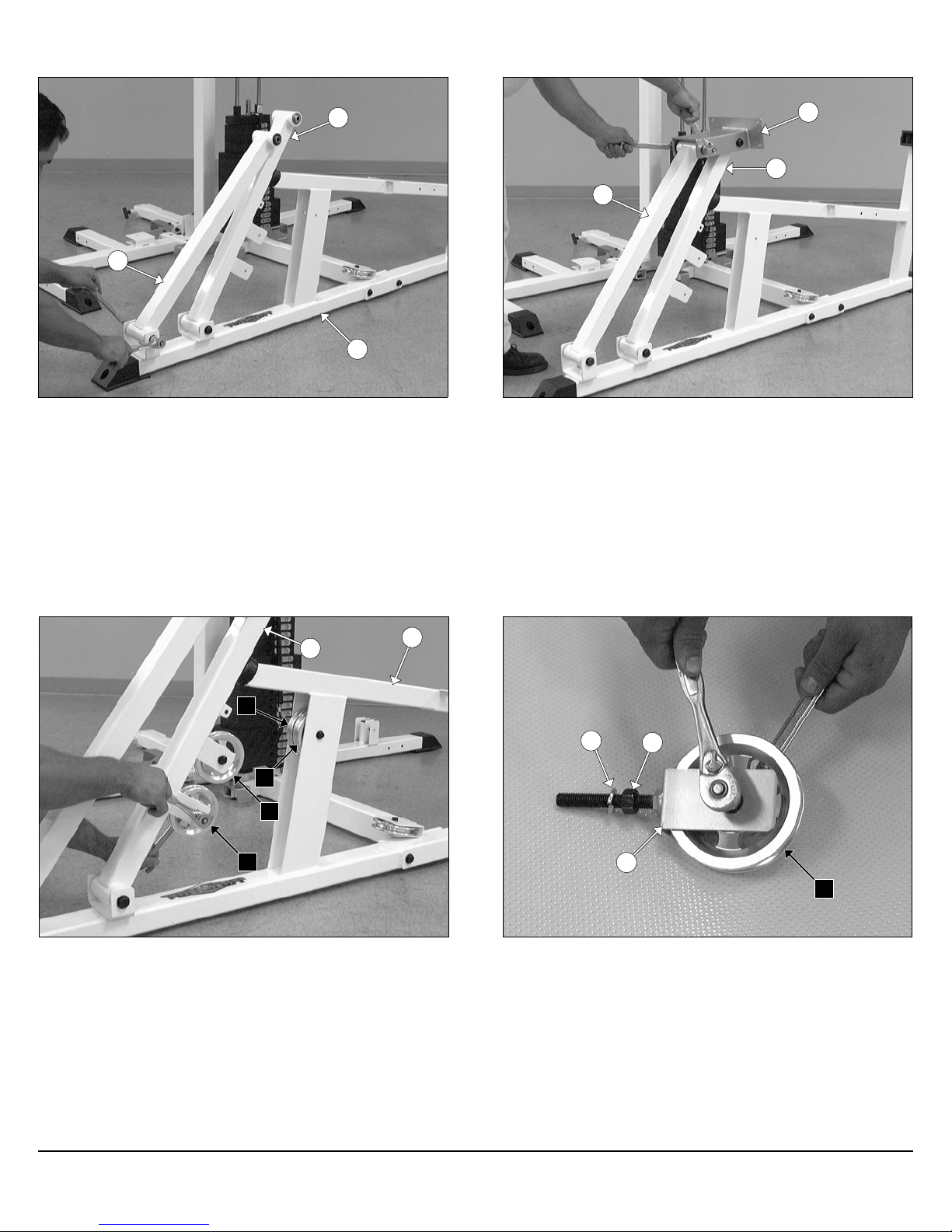
FIG. 3 Attach the Fulcrum with Brackets (#52) and the Fulcrum
(#51) to the Leg Press Main Frame (#47) using two Hex Head Cap
Screws 1/2-13 X 5 1/2 (#111), four Flat Washers SAE 1/2” (#93), and
two Nylon Insert Jam Lock Nuts 1/2-13 (#127).
50
52
51
FIG. 4 Next, attach the Foot Plate Bracket (#50) to the Fulcrum
with Brackets (#52) and the Fulcrum (#51) using two Hex Head Cap
Screws 1/2-13 X 5 1/2 (#111), four Flat Washers SAE 1/2” (#93), and
two Nylon Insert Jam Lock Nuts 1/2-13 (#127).
52
47
D1
D3
D2
D4
FIG. 5 Attach two Pulleys 4 1/2 Rd. (#78-Labeled D1, D3) to the
Leg Press Main Frame (#47) using one Hex Head Cap Screw 3/8-16
X 2 3/4 (#104), two Flat Washers SAE 3/8” (#94), and one Nylon Insert
Jam Lock Nut 3/8-16 (#123).
Next, attach two Pulleys 4 1/2 Rd. (#78-Labeled D2, D4) to the Ful-
crum with Brackets (#52) using two Hex Head Cap Screws 3/8-16 X 1
3/4 (#101), four Flat Washers SAE 3/8” (#94), and two Nylon Insert Jam
Lock Nuts 3/8-16 (#123).
176
89
45
D7
FIG. 6 Locate one of the Adjustable Pulley Brackets (#45) and attach one Pulley 4 1/2 Rd. (#78-Labeled D7) using one Hex Head Cap
Screw 3/8-16 X 1 3/4 (#101), two Flat Washers SAE 3/8” (#94), and
one Nylon Insert Jam Lock Nut 3/8-16 (#123). Next, thread one Finished Hex Nut 1/2-13 (#89) and insert one Split Lock Washer
1/2” (#176) onto the Screw of the Adjustable Pulley Bracket (#45).
Leg Press Station
2
Page 4

89
176
90
56
45
1
176
55
FIG. 7 Next, attach the assembled Adjustable Pulley Bracket
(#45) to the receptacle of the Weight Stack Frame (#1) using one Split
Lock Washer 1/2” (#176) and one Finished Hex Nut 1/2-13 (#89).
52
56
FIG. 8 Thread one Finished Hex Jam Nut 1/2-13 (#90) and insert
one Split Lock Washer 1/2” (#176) onto the Screw of the Leg Press
Cable (#55). Next, Locate the Swivel Cable End (#56) and thread it to
the bolt of the Leg Press Cable (#55).
D1
55
55
FIG. 9 Next, attach the Swivel Cable End (#56) to the Fulcrum
with Brackets (#52) using one Hex Head Cap Screw 3/8-16 X 1 3/4
(#101), two Flat Washers SAE 3/8” (#94), one Nylon Insert Jam Lock
Nut 3/8-16 (#123).
3
D2
FIG. 10 Route the Leg Press Cable (#55) around the Pulley 4 1/2
Rd. (#78-Labeled D1). Next, route under then up the Pulley 4 1/2 Rd.
(#78-Labeled D2).
Note: Refer to the Cable Mapping Diagram on fold-out page 6for
further detailed illustration of the Leg Press Cable (#55) routing.
Leg Press Station
Page 5

Assembly Instructions
D3
55
D4
FIG. 11 Next, route the Leg Press Cable (#55) around the Pulley 4
1/2 Rd. (#78-Labeled D3). Next, route around the Pulley 4 1/2 Rd.
(#78-Labeled D4). Continue to route through the opening of the Leg
Press Main Frame (#47).
Note: Refer to the Cable Mapping Diagram on fold-out page 6
for further detailed illustration of the Leg Press Cable (#55)
routing.
47
1
55
D6
46
D5
FIG. 12 Route the Leg Press Cable (#55) around the Pulley 4 1/2
Rd. (#78-Labeled D5), and then through the tube of the Leg Press Bot-
tom Connector (#46). Next, route under the Pulley 4 1/2 Rd. (#78Labeled D6).
Note: Refer to the Cable Mapping Diagram on fold-out page 6
for further detailed illustration of the Leg Press Cable (#55)
routing.
D7
55
72
FIG. 13 Continue to route up and over the Pulley 4 1/2 Rd. (#78Labeled D7).
Next, attach the Leg Press Cable (#55) to the Top Plate/Selector Bar
(#72) using one Split Bolt 1/2-13 X 1 (#171), and one Split Lock Washer
(#176).
Note: Refer to Fig. B on fold-out page 6 for further clarification
of this hardware assembly.
Fully Fasten: Proceed fully fasten this hardware assembly.
31
32
FIG. 14 Attach the Right Handle (#31) and the Left Handle (#32) to
the Leg Press Main Frame (#47), in the position as shown above,
using two Hex Head Cap Screws 3/8-16 X 3 1/4 (#105), four Flat
Washers SAE 3/8” (#94), and two Nylon Insert Lock Nuts 3/8-16
(#125).
47
Leg Press Station
4
Page 6

53
140
47
FIG. 15 Affix the Seat Pad (#53) to the Leg Press Main Frame
(#47) using two Hex Head Cap Screws 3/8-16 X 1 1/4 (#99), one Hex
Head Cap Screw 3/8-16 X 3 (#113-Labeled with a black arrow), and
three Flat Washers SAE 3/8” (#94).
54
49
FIG. 16 Using a rubber mallet, insert one Plastic Insert Cap 1 3/4”
Sq. (#140) into the tube-end of the Adjustable Back Pad Tube (#49).
Next, attach the Adjustable Back Pad Tube (#49) to the Back Pad
(#54) using two Hex Head Cap Screws 3/8-16 X 1 1/4 (#99), and two
Flat Washers SAE 3/8” (#94).
54
49
179
47
FIG. 17 Insert the assembled Adjustable Back Pad Tube (#49) to
the Leg Press Main Frame (#47).
48
50
FIG. 18 Caution: It is strongly recommended to use another
person in assisting with this assembly.
Attach the Foot Plate (#48) to the Foot Plate Bracket (#50) using four
Flat Head Socket Cap Screws 3/8-16 X 1 1/4 (#91), four Flat Washers
SAE 3/8” (#94), and four Nylon Insert Lock Nuts 3/8-16 (#125).
5
Leg Press Station
Page 7

CHART
BOLD FONT = SUB-ASSEMBLY PARTS
REGULAR FONT = HARDWARE
Leg Press Station (Deluxe)
Parts List
ITEM NO. DESCRIPTION PART NO. QTY. ITEM NO. DESCRIPTION PART NO. QTY.
31 RIGHT HANDLE UP0270 1
32 LEFT HANDLE UP0271 1
45 ADJUSTABLE PULLEY BRACKET UP0127 1
46 LEG PRESS BOTTOM CONNECTOR UP2011 1
47 LEG PRESS MAIN FRAME UP2012 1
48 FOOT PLATE UP2014 1
49 ADJUSTABLE BACK PAD TUBE UP2015 1
50 FOOT PLATE BRACKET UP2018 1
51 FULCRUM UP2019 1
52 FULCRUM WITH BRACKETS UP2020 1
53 SEAT PAD UP0146 1
54 BACK PAD UP0145 1
55 LEG PRESS CABLE UP2024 1
56 SWIVEL CABLE END UP2032 1
76 ALUMINUM CAP 1" RD. (CAP-100) BNH0537 2 144 PLASTIC TUBE GUIDE W/LIP-TEETH 2 1/4" SQ. BNH0059 2
78 ALUMINUM PULLEY 3/8" X 4 1/2" BNH0069 7 153 RUBBER BUMPER 3/8 X 2 1/2 BNH05111
80 BEARING 6203 W/TWO 1/2 BUSHINGS BNH0835 8 156 RUBBER GRIP 1 ID X .125 X 8 BNH0966 2
82 BRONZE BUSHING 3/8 X 1/2 X 5/16 BNH0737 2 169 SOCKET SET SCREW ALLOY 10-32 X 1/8 BNH0473 4
89 FINISHED HEX NUT B/O 1/2-13 BNH0201 2 171 SPLIT BOLT Z/P 1/2-13 X 1 BNH04791
90 FINISHED HEX JAM NUT B/O 1/2-13 BNH0655 1 174 SPLIT LOCK WASHER 3/8" BNH0658 1
91 FLAT HEAD SOCKET CAP SCREW B/O 3/8-16 X 1 1/4 BNH0667 4 176 SPLIT LOCK WASHER Z/P 1/2" BNH0572 4
92 FLAT PHILLIPS MACHINE SCREW 8-32 X 1/4 BNH0408 1 177 STEEL BUMPER WASHER Z/P 3/8" BNH04981
93 FLAT WASHER SAE 1/2" BNH0238 12 179 TURN/PULL PIN W/KNOB AND LOCK BNH0989 1
94 FLAT WASHER SAE 3/8" BNH0239 29 180 URETHANE BUMPER 1 3/4 BNH0229 1
96 CABLE HEX TAP BOLT 1/2-13 X 3 1/2 BNH1131 1 186 DECAL-ADJUST CABLE HERE BNH0789 1
99 HEX HEAD CAP SCREW 3/8-16 X 1 1/4 BNH0273 4 187 DECAL-EXERCISE LEG PRESS STATION BNH1675 1
100 HEX HEAD CAP SCREW 3/8-16 X 1 1/2 BNH0303 1
101 HEX HEAD CAP SCREW 3/8-16 X 1 3/4 BNH0274 4
102 HEX HEAD CAP SCREW 3/8-16 X 2 BNH0279 2
104 HEX HEAD CAP SCREW 3/8-16 X 2 3/4 BNH0278 1
105 HEX HEAD CAP SCREW 3/8-16 X 3 1/4 BNH0312 4
111 HEX HEAD CAP SCREW GR-5 B/O 1/2-13 X 5 1/2 BNH0267 4
112 HEX HEAD CAP SCREW GR-5 B/O 1/2-13 X 4 3/4 BNH0895 2
113 HEX HEAD CAP SCREW GR-5 B/O 3/8-16 X 3 BNH0282 1
123 NYLON INSERT JAM LOCK NUT 3/8-16 BNH0365 6
124 NYLON INSERT LOCK NUT 1/2-13 BNH0212 2
125 NYLON INSERT LOCK NUT 3/8-16 BNH0214 8
127 NYLON INSERT JAM LOCK NUT 1/2-13 BNH0366 4
132 PLASTIC END CAP 2 X 3 BNH0606 2
140 PLASTIC INSERT CAP 13/4" SQ BNH0053 1
Leg Press Station (Standard)
Parts List
All parts same as Leg Press Station (Deluxe), except for the part listed below
ITEM NO. DESCRIPTION PART NO. QTY. ITEM NO. DESCRIPTION PART NO. QTY.
78 NYLON PULLEY 3/8 X 4 1/2 BNH0506 7
Leg Press Station 8
Page 8

DO NOT DISCARD THIS MANUAL
TUFFSTUFF WARRANTY
TuffStuff warrants to the original purchaser that TuffStuff equipment will be free from defects in material and
workmanship. All warranty periods begin to run from the date of delivery to the original purchaser. The warranty
and remedies set forth herein are conditioned upon proper storage, installation, use and maintenance and conformance with any recommendations of TuffStuff. This warranty does not cover products not manufactured by
TuffStuff or products which are altered without the express written consent of TuffStuff. This warranty as specified:
FULL COMMERCIAL WARRANTY (more than 5 hours of use per day): a) Frames, welds, cams and
weight plates -- Lifetime, b) Pivot bearings, pulleys, bushings, gas shocks and guide rods -- Five (5) years, c)
Belts, linear bearings and pull-pin components -- One (1) year, and d) Upholstery, cables, finish and rubber grips
-- Six (6) months.
LIGHT COMMERCIAL WARRANTY (less than 5 hours of use per day): a) Frames, welds, cams and weight
plates -- Lifetime, b) Pivot bearings, pulleys, bushings, gas shocks and guide rods -- Five (5) years, c) Linear
bearings, finish and pull-pin components -- One (1) year, and d) Upholstery, cables and rubber grips -- Three
(3) months, and all other parts not mentioned elsewhere in this warranty will expire one (1) year from the date of
delivery to the original purchaser. The obligation of TuffStuff under this warranty is limited to repairing or replacing warranted defective parts, as TuffStuff may elect, at TuffStuff’s facility in Pomona, California, without
charge to purchaser for either parts or labor. Purchaser is responsible for installation of repaired or replaced parts,
and all transportation and insurance costs on returned or replaced equipment to and from TuffStuff’s facility in
Pomona.
THE FOREGOING SHALL CONSTITUTE THE SOLE REMEDY OF THE PURCHASER AND THE
SOLE LIABILITY OF TUFFSTUFF WITH REGARD TO WARRANTY. NO IMPLIED STATUTORY
WARRANTY OR IMPLIED STATUTORY WARRANTY OF MERCHANTABILITY OR FITNESS
FOR A PARTICULAR PURPOSE SHALL APPLY. IN NO EVENT, WHETHER AS A RESULT OF
BREACH OF CONTRACT, WARRANTY, NEGLIGENCE OR OTHERWISE, SHALL TUFFSTUFF BE
LIABLE FOR SPECIAL, INCIDENTAL OR CONSEQUENTIAL DAMAGES INCLUDING, BUT NOT
LIMITED TO, LOSS OF PROFITS OR REVENUE, LOSS OF USE OF EQUIPMENT, COST OF CAPITAL, COST OF SUBSTITUTION EQUIPMENT, DOWNTIME COST, OR CLAIMS OF CUSTOMERS
OR PURCHASER FROM SUCH DAMAGE.
This written warranty is the final, complete and exclusive agreement of the parties with respect to the quality or
performance of the equipment and no action for breach of this written warranty or any implied warranty shall be
commenced more than one (1) year after the accrual of the cause o f action. No modification of this warranty or
waiver of its terms shall be binding on either party unless approved in writing by an authorized representative of
the party. Contact TuffStuff Fitness Equipment, Inc. at 1325 E. Franklin Avenue, Pomona, California 91766,
before returning any defective equipment.
TuffStuff Fitness Equipment, Inc.
1325 E. Franklin Avenue
Pomona, CA 91766, USA
Ph: 909-629-1600 Fax: 909-629-4967
E-mail: service@tuffstuff.net Net: www.tuffstuff.net
 Loading...