

Page 1
ASSEMBLY INSTRUCTIONS
Apollo Modular Gym System
Inner Outer Thigh Station
Standard
Deluxe
America’s Premier Exercise Equipment
Revision Date 08-23-05
Inner Outer Thigh Station Rev0
Page 2

About the Inner Outer Thigh Station
Congratulations on your new purchase of the Inner Outer Thigh
Station. We hope you are completely satisfi ed with this product
and wish you many years of enjoyment.
Prior to the Assembly of the Inner Outer Thigh Station
1. We advise you to consult your local Tuff Stuff retailer if you
should have a question or problem regarding the proper
assembly of this unit.
Tuff Stuff Equipment
This Tuffstuff product has been built to precise quality standards
and has been carefully packaged to ensure that damage will
not occur during shipment. The TuffStuff Warranty and signature
indicating fi nal inspection has been conducted by our line foreman,
is an expression of our confi dence in the completeness, the
materials, and workmanship of this product.
Warranty
SEE A COPY OF WARRANTY ON BACK PAGE.
Registration Card
To avoid unnecessary delays in warranty service and to insure that
a permanent record of your purchase is on fi le with our factory,
be sure to complete the warranty registration card and send it to
TuffStuff Fitness Equipment today.
Specifi cations
1. Maximum Wt. Capacity - 200 lbs.
2. Total Machine Weight - 90 lbs.
2. Neatly organize and identify all parts according to the Parts List
and the Exploded View Diagram.
Tool Requirements
1. One 7/8” combination wrench
2. One 3/4” combination wrench
3. One 9/16” combination wrench
4. One 1/2” combination wrench
5. One ratchet
6. One 9/16” socket
7. One rubber mallet
8. External retaining-ring pliers
9. Measuring tape
10. Utility knife
Note: Due to continuing product improvements, specifi cations and designs are subject to change
without notice.
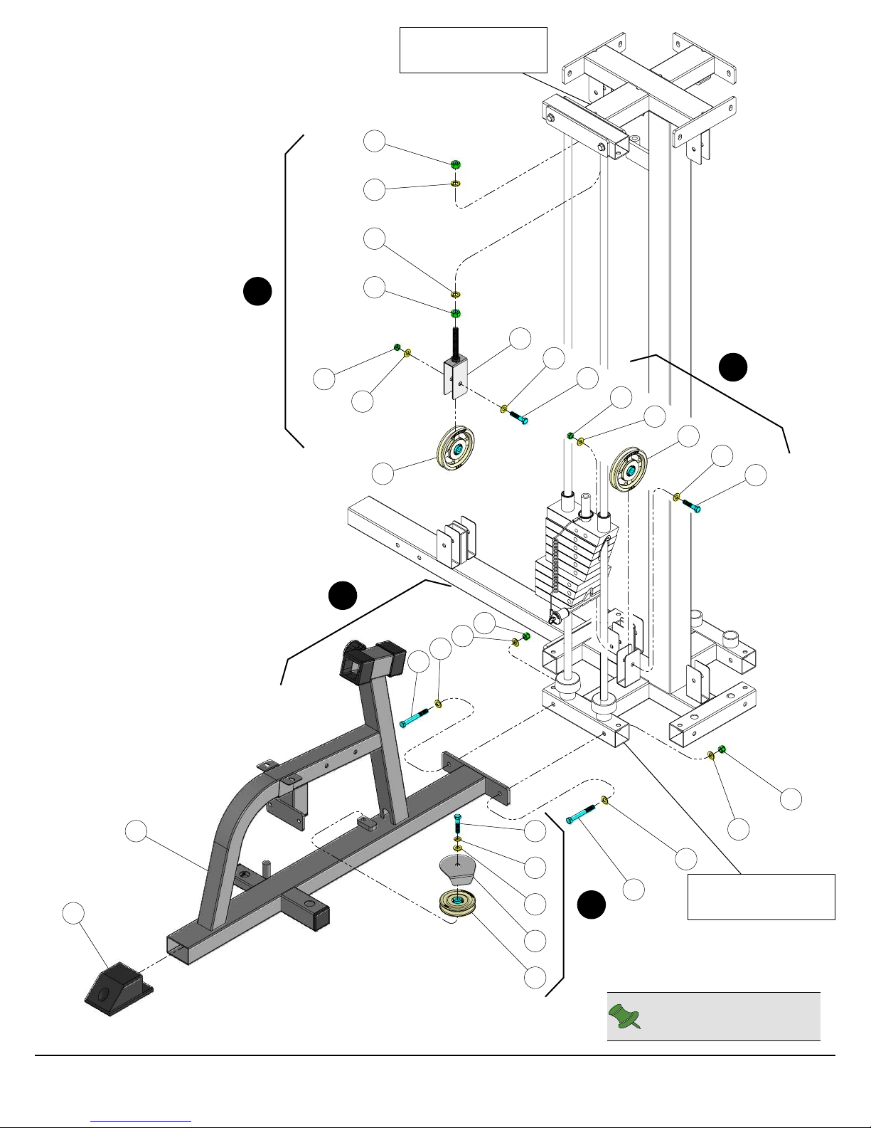
Step 1 Main Frame Assembly
A
Assemble the Adjustable Pulley Bracket (#3) to the Weight Stack Frame using hardware shown.
Attach a Pulley 3/8 X 4 1/2 (#23) to the Weight Stack Frame using hardware shown.
B
Using a rubber mallet, insert a Plastic End Cap 2 X 3 (#42) onto the tube-end of the Main Frame (#11). Next, affi x the
C
Main Frame (#11) to the Weight Stack Frame using hardware shown.
Attach a Pulley 3/8 X 3 1/2 (#22) and a Small Cover Plate 3 1/2 Pulley (#19) to the Main Frame (#11) using hardware
D
shown.
Assembly List
Item # Description Qty. Item # Description Qty.
3 ADJUSTABLE PULLEY BRACKET 1 32 HEX HEAD CAP SCREW GR-5 B/O 3/8-16 X 1 3/4 3
11 MAIN FRAME 1 34 HEX HEAD CAP SCREW GR-5 B/O 3/8-16 X 3 1/4 2
19 SMALL COVER PLATE 3 1/2” PULLEY 1 39 NYLON INSERT JAM LOCK NUT B/O 3/8-16 2
22 PULLEY 3/8” X 3 1/2” 1 40 NYLON INSERT LOCK NUT B/O 3/8-16 2
23 PULLEY 3/8” X 4 1/2” 2 42 PLASTIC END CAP 2 X 3 1
28 FINISHED HEX NUT B/O 1/2-13 2 60 SPLIT LOCK WASHER B/O 3/8” 1
30 FLAT WASHER SAE B/O 3/8” 9 61 SPLIT LOCK WASHER Z/P 1/2” 2
1
Inner Outer Thigh Station
Page 3
28
61
61
Weight Stack
Frame
A
39
C
30
28
23
34
30
30
40
3
30
32
39
30
23
B
30
32
11
42
Inner Outer Thigh Station
32
60
30
19
22
D
30
30
34
Weight Stack
Frame
Note: Some parts have
been cut away for clarity.
40
2
Page 4
Step 2 Attach Pivot Legs to Main Frame
A
Attach a Pulley 3/8 X 3 1/2 (#22) and a Small Cover Plate 3 1/2 Pulley (#19) to the Cam
Support Tube (#5) using hardware shown.
Insert the Pivot Axles (#14) into the receptacles of the Main Frame (#11). Next, attach the
B
Cam Support Tube (#5) and the Adjustable Cam Plate (#2) to the right side Pivot Axle
(#14).
Attach the Pivot Legs (#8, 16) to the Pivot Axles (#14).
C
C
16
B
33
30
19
A
22
2
30
405
14
Assembly List
Item # Description Qty.
2 ADJUSTABLE CAM PLATE 1
5 CAM SUPPORT TUBE 1
8 LEFT PIVOT LEG 1
14 PIVOT AXLE 1 X 10 13/16 2
16 RIGHT PIVOT LEG 1
19 SMALL COVER PLATE 3 1/2” PULLEY 1
22 PULLEY 3/8” X 3 1/2” 1
30 FLAT WASHER SAE B/O 3/8” 2
33 HEX HEAD CAP SCREW GR-5 B/O 3/8-16 X 3 1
40 NYLON INSERT LOCK NUT B/O 3/8-16 1
3
11
8
14
Note: Some parts have
been cut away for clarity.
Inner Outer Thigh Station
Page 5

Step 3 Connect Pivot Legs
A
Maneuver the two Pivot Axles (#14) into the holes on the bottom side of the Pivot Axle Support Tube (#15). Next,
loosely fasten the Pivot Axle Support Tube (#15) along with the two captive Pivot Axles (#14) to the Main Frame (#1 1)
using hardware shown.
Attach the Pivot Actuator Plate (#13) to the Pivot Legs (#8, 16) receptacles
B
and secure it into place using hardware shown.
Tightly fasten the Pivot Axle Support Tube (#15) to the Main Frame (#11).
C
Then, thread the four Socket Set Screws 3/8-16 X 1/2 (#57) to align the Pivot
Legs (#8, 16).
Assembly List
Item # Description Qty.
13 PIVOT ACTUATOR PLATE 1
15 PIVOT AXLE SUPPORT TUBE 1
30 FLAT WASHER SAE B/O 3/8” 6
34 HEX HEAD CAP SCREW GR-5 B/O 3/8-16 X 3 1/4 2
40 NYLON INSERT LOCK NUT B/O 3/8-16 4
57 SOCKET SET SCREW ALLOY 3/8-16 X 1/2 4
A
16
30 57
34
14
14
C
15
57
5730
30
40
30
B
13
8
30
40
Inner Outer Thigh Station
30
40
Note: Some parts have
been cut away for clarity.
4
Page 6

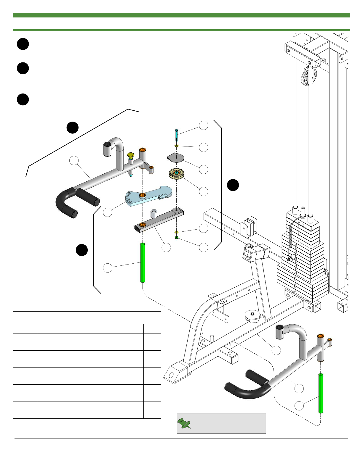
Step 4 Handles and Leg Pad Pivot Brackets Assembly
A
Attach the Handles (#6, #7) to the Main Frame (#11) using hardware shown.
Insert the Leg Pad Pivot Brackets (#10) into the receptacles of the Pivot Legs (#8, 16). Next, secure the Leg Pad
B
Brackets (#10) using the two Retaining Snap Rings (#49). If possible, use special snap ring pliers for this job. If tool is
not available, carefully work each Retaining Snap Ring (#49) into the grooves of the Leg Pad Pivot Brackets (#10) then
push up alternately with a screw driver working the Retaining Snap Ring into the groove.
C
Attach the Leg Pads (#9) to the Leg Pad Pivot Brackets (#10) using hardware shown.
Assembly List
Item # Description Qty. Item # Description Qty.
6 HANDLE (LT) 1 32 HEX HEAD CAP SCREW GR-5 B/O 3/8-16 X 1 3/4 1
7 HANDLE (RT) 1 34 HEX HEAD CAP SCREW GR-5 B/O 3/8-16 X 3 1/4 2
9 LEG PAD 2 40 NYLON INSERT LOCK NUT B/O 3/8-16 2
10 LEG PAD PIVOT BRACKET 2 49 RETAINING SNAP RING EXT. PLAIN .925 X 1 X .042 2
26 BUTTON HEAD SOC CAP SCREW B/O 3/8-16 X 1 1/4 3 50 RUBBER BUMPER W/WASHER 3/8 X 1 1/2 1
30 FLAT WASHER SAE B/O 3/8” 7
5
Inner Outer Thigh Station
Page 7

Note: Some parts have
been cut away for clarity.
26
30
A
26
30
10
9
40
30
7
11
40
30
16
6
30
49
49
B
C
Inner Outer Thigh Station
30
8
9
10
50
26
32
34
6
Page 8

Step 5 Seat Pad and Back Pad Assembly
A
Attach the Seat Pad (#17) to the Main Frame (#11) using hardware shown.
Attach the Back Pad (#4) to the Adjustable Back Pad Tube (#1) using hardware shown. Next, insert the Adjustable
B
Back Pad Tube (#1) into the receptacle of the Main Frame (#11).
C
Attach a Pulley 3/8 X 4 1/2 (#23) to the Floating Pulley Bracket (#12) using hardware shown.
Assembly List
Item # Description Qty. Item # Description Qty.
1 ADJUSTABLE BACK PAD TUBE 1 30 FLAT WASHER SAE B/O 3/8” 6
4 BACK PAD 1 31 HEX HEAD CAP SCREW GR-5 B/O 3/8-16 X 1 1/4 4
12 FLOATING PULLEY BRACKET 1 32 HEX HEAD CAP SCREW GR-5 B/O 3/8-16 X 1 3/4 1
17 SEAT PAD 1 39 NYLON INSERT JAM LOCK NUT B/O 3/8-16 1
23 PULLEY 3/8” X 4 1/2” 1
7
Inner Outer Thigh Station
Page 9

C
39
30
12
30
32
23
B
31
30
A
4
17
31
30
1
11
30
31
Inner Outer Thigh Station
30
31
Note: Some parts have
been cut away for clarity.
8
Page 10

Step 6 Cable Routing
A. Connect the Weight Stack Cable (#20) to the Top Plate Selector Bar using hardware shown. See FIG. A.
B. Next, route the Weight Stack Cable (#20) up and over the Pulley 3/8 X 4 1/2 (#23-Labeled G1 ), then route down and under
G2
the Pulley 3/8 X 4 1/2 (#23-Labeled
) .
C. Connect the Weight Stack Cable (#20) to the Weight Stack Frame using hardware shown. See FIG. B.
D. Secure the looped end of the Short Cable (#18) to the Floating Pulley Bracket (#12) using one Shoulder Bolt 3/8 X 3/4
(#54) and one Nylon Insert Lock Nut 5/16-18 (#41). See FIG. C.
G3
E. Route the Short Cable (#18) down and under the Pulley 3/8 X 4 1/2 (#23-Labeled
F. Next, route the cable under the Weight Stack. Then, route the cable around the Pulleys 3/8” X 3 1/2” (#22-Labeled
G5
) passing the cable between the pulleys and the Cover Plates.
) .
G4
&
G. Attach the Short Cable (#18) to the Adjustable Cam Plate (#2) and secure it into place using the Socket Head Cap Screw
1/4-20 X 3/4 (#55). See FIG. D.
Assembly List
Item # Description Qty. Item # Description Qty.
18 SHORT CABLE 1 55 SOCKET HEAD CAP SCREW B/O 1/4-20 X 3/4 1
20 WEIGHT STACK CABLE 1 58 SPLIT BOLT Z/P 1/2-13 X 1 1
28 FINISHED HEX NUT B/O 1/2-13 1 59 SPLIT HEX TAP BOLT GR-5 B/O 1/2-13 X 3 1/2 1
41 NYLON INSERT LOCK NUT B/O 5/16-18 1 61 SPLIT LOCK WASHER Z/P 1/2” 2
54 SHOULDER BOLT ALLOY 3/8 X 3/4 1
9
Inner Outer Thigh Station
Page 11

CHART
BOLD FONT = SUB-ASSEMBLY PARTS
REGULAR FONT = HARDWARE
Inner Outer Thigh Station (Deluxe)
Parts List
ITEM NO. DESCRIPTION PART NO. QTY. ITEM NO. DESCRIPTION PART NO. QTY.
1 ADJUSTABLE BACK PAD TUBE UP0361 1
2 ADJUSTABLE CAM PLATE UP0846 1
3 ADJUSTABLE PULLEY BRACKET UP0127 1
4 BACK PAD UP0158 1
5 CAM SUPPORT TUBE UP2886 1
6 HANDLE (LT) UP0271 1
7 HANDLE (RT) UP0270 1
8 LEFT PIVOT LEG UP0352 1
9 LEG PAD UP0365 2
10 LEG PAD PIVOT BRACKET UP0364 2
11 MAIN FRAME UP2116 1
12 FLOATING PULLEY BRACKET UP0110 1
13 PIVOT ACTUATOR PLATE UP0357 1
14 PIVOT AXLE 1 X 10 13/16 UP0363 2
15 PIVOT AXLE SUPPORT TUBE UP0848 1
16 RIGHT PIVOT LEG UP0852 1
17 SEAT PAD UP0188 1
18 SHORT CABLE UP2117 1
19 SMALL COVER PLATE 3 1/2" PULLEY UP1000 2
20 WEIGHT STACK CABLE UP2118 1
21 ALUMINUM CAP 1.020" RD BNH0537 2 54 SHOULDER BOLT ALLOY 3/8 X 3/4 BNH0718 1
22 ALUMINUM PULLEY 3/8" X 3 1/2" BNH1266 2 55 SOCKET HEAD CAP SCREW B/O 1/4-20 X 3/4 BNH0452 1
23 ALUMINUM PULLEY 3/8" X 4 1/2" BNH0069 3 56 SOCKET SET SCREW ALLOY 10-32 X 1/8 BNH0473 4
24 BRONZE BUSHING 1 X 1 1/4 X 3/4 X 1 1/2 X 1/8 BNH0527 8 57 SOCKET SET SCREW ALLOY 3/8-16 X 1/2 BNH0474 4
25 BRONZE BUSHING 1/2 X 5/8 X 1/2 X 7/8 X 1/8 BNH0528 4 58 SPLIT BOLT Z/P 1/2-13 X 1 BNH0479 1
26 BUTTON HEAD SOCKET CAP SCREW B/O 3/8-16 X 1 1/4 BNH0896 3 59 SPLIT HEX TAP BOLT GR-5 B/O 1/2-13 X 3 1/2 BNH1131 1
27 DECAL-DANGER TIGHTEN THIS RET..., 3/4 X 1 1/2 BNH0142 1 60 SPLIT LOCK WASHER B/O 3/8" BNH0658 1
28 FINISHED HEX NUT B/O 1/2-13 BNH0201 3 61 SPLIT LOCK WASHER Z/P 1/2" BNH0572 4
29 FLAT PHILLIPS MACHINE SCREW 8-32 X 1/4 BNH0408 1 62 TURN/PULL PIN W/KNOB AND LOCK BNH0989 1
30 FLAT WASHER SAE B/O 3/8" BNH0239 30 63 UHMW PLASTIC 3/4" ID X 1 1/2" OD X 1 1/2" H BNH12721
31 HEX HEAD CAP SCREW GR-5 B/O 3/8-16 X 1 1/4 BNH0273 4 64 URETHANE BUMPER 1 3/4 BNH0229 1
32 HEX HEAD CAP SCREW GR-5 B/O 3/8-16 X 1 3/4 BNH0274 5 65 DECAL-EXERCISE INNER OUTER THIGH STATION BNH1678 1
33 HEX HEAD CAP SCREW GR-5 B/O 3/8-16 X 3 BNH0282 1
34 HEX HEAD CAP SCREW GR-5 B/O 3/8-16 X 3 1/4 BNH0312 6
35 HEX KEY ALLOY 3/16" BNH0371 1
36 HEX KEY ALLOY 3/32" BNH0372 1
37 HEX KEY ALLOY 7/32" BNH0575 1
38 NYLON BUSHING 1 X 1 1/2 X 7/8 X 1 3/4 X 1/8 BNH0531 4
39 NYLON INSERT JAM LOCK NUT B/O 3/8-16 BNH0365 3
40 NYLON INSERT LOCK NUT B/O 3/8-16 BNH0214 9
41 NYLON INSERT LOCK NUT B/O 5/16-18 BNH0215 1
42 PLASTIC END CAP 2 X 3 BNH0606 1
43 PLASTIC INSERT CAP 1 3/4" RD 10-14 GA BNH0011 4
44 PLASTIC INSERT CAP 1 3/4" SQ 10-14 GA BNH0053 1
45 PLASTIC INSERT CAP 1" X 2"_ 10-14 GA BNH0005 3
46 PLASTIC INSERT CAP 2" SQ 10-14 GA BNH0012 4
47 PLASTIC TUBE GUIDE W/LIP-TEETH 2 1/4" SQ BNH0059 2
48 PULL PIN 1/2 X 5 5/8 (YELLOW KNOB) BNH0701 1
49 RETAINING SNAP RING EXT. PLAIN .925 X 1 X .042 BNH0419 2
50 RUBBER BUMPER W/WASHER 3/8 X 1 1/2 BNH0514 1
51 RUBBER GRIP 1 ID X .125 X 8 BNH0966 2
52 RUBBER TUBE 1.625 ID X .125 WALL X 11 3/4 BNH0980 2
53 RUBBER TUBE 1.625 ID X .125 WALL X 6 BNH0978 2
Inner Outer Thigh Station (Standard)
Parts List
All parts same as Inner Outer Thigh Station (Deluxe), except for the parts listed below
ITEM NO. DESCRIPTION PART NO. QTY. ITEM NO. DESCRIPTION PART NO. QTY.
22 NYLON PULLEY 3/8 X 3 1/2 BNH0553 2 23 NYLON PULLEY 3/8 X 4 1/2 BNH0506 3
Inner Outer Thigh Station
12
Page 12

DO NOT DISCARD THIS MANUAL
TUFFSTUFF WARRANTY
TuffStuff warrants to the original purchaser that TuffStuff equipment will be free from defects in material and
workmanship. All warranty periods begin to run from the date of delivery to the original purchaser. The warranty
and remedies set forth herein are conditioned upon proper storage, installation, use and maintenance and conformance with any recommendations of TuffStuff. This warranty does not cover products not manufactured by
TuffStuff or products which are altered without the express written consent of TuffStuff. This warranty as specified:
FULL COMMERCIAL WARRANTY (more than 5 hours of use per day): a) Frames, welds, cams and
weight plates -- Lifetime, b) Pivot bearings, pulleys, bushings, gas shocks and guide rods -- Five (5) years, c)
Belts, linear bearings and pull-pin components -- One (1) year, and d) Upholstery, cables, finish and rubber grips
-- Six (6) months.
LIGHT COMMERCIAL WARRANTY (less than 5 hours of use per day): a) Frames, welds, cams and weight
plates -- Lifetime, b) Pivot bearings, pulleys, bushings, gas shocks and guide rods -- Five (5) years, c) Linear
bearings, finish and pull-pin components -- One (1) year, and d) Upholstery, cables and rubber grips -- Three
(3) months, and all other parts not mentioned elsewhere in this warranty will expire one (1) year from the date of
delivery to the original purchaser. The obligation of TuffStuff under this warranty is limited to repairing or replacing warranted defective parts, as TuffStuff may elect, at TuffStuff’s facility in Pomona, California, without
charge to purchaser for either parts or labor. Purchaser is responsible for installation of repaired or replaced parts,
and all transportation and insurance costs on returned or replaced equipment to and from TuffStuff’s facility in
Pomona.
THE FOREGOING SHALL CONSTITUTE THE SOLE REMEDY OF THE PURCHASER AND THE
SOLE LIABILITY OF TUFFSTUFF WITH REGARD TO WARRANTY. NO IMPLIED STATUTORY
WARRANTY OR IMPLIED STATUTORY WARRANTY OF MERCHANTABILITY OR FITNESS
FOR A PARTICULAR PURPOSE SHALL APPLY. IN NO EVENT, WHETHER AS A RESULT OF
BREACH OF CONTRACT, WARRANTY, NEGLIGENCE OR OTHERWISE, SHALL TUFFSTUFF BE
LIABLE FOR SPECIAL, INCIDENTAL OR CONSEQUENTIAL DAMAGES INCLUDING, BUT NOT
LIMITED TO, LOSS OF PROFITS OR REVENUE, LOSS OF USE OF EQUIPMENT, COST OF CAPITAL, COST OF SUBSTITUTION EQUIPMENT, DOWNTIME COST, OR CLAIMS OF CUSTOMERS
OR PURCHASER FROM SUCH DAMAGE.
This written warranty is the final, complete and exclusive agreement of the parties with respect to the quality or
performance of the equipment and no action for breach of this written warranty or any implied warranty shall be
commenced more than one (1) year after the accrual of the cause of action. No modific ation of this warranty or
waiver of its terms shall be binding on either party unless approved in writing by an authorized representative of
the party. Contact TuffStuff Fitness Equipment, Inc. at 1325 E. Franklin Avenue, Pomona, California 91766,
before returning any defective equipment.
TuffStuff Fitness Equipment, Inc.
1325 E. Franklin Avenue
Pomona, CA 91766, USA
Ph: 909-629-1600 Fax: 909-629-4967
E-mail: service@tuffstuff.net Net: www.tuffstuff.net
 Loading...