

Page 1
OWNER’S MANUAL
TABLE OF CONTENTS:
Introduction - Pg. 1
Safety Precautions - Pg. 2
Assembly Instructions
Pg. 3 - Pg. 28
Parts List - Fold-out Pg. 20
Cable Mapping Diagrams
Vertical Multi-Press Station Pg. 21
Mid Row Station Pg. 23
Leg Developer Station Pg. 25
Exploded View Diagrams
Vertical Multi-Press Station Pg. 22
Mid Row Station Pg. 24
Leg Developer Station Pg. 26
Maintenance - Pg. 29 - Pg. 30
Warranty - Back Page
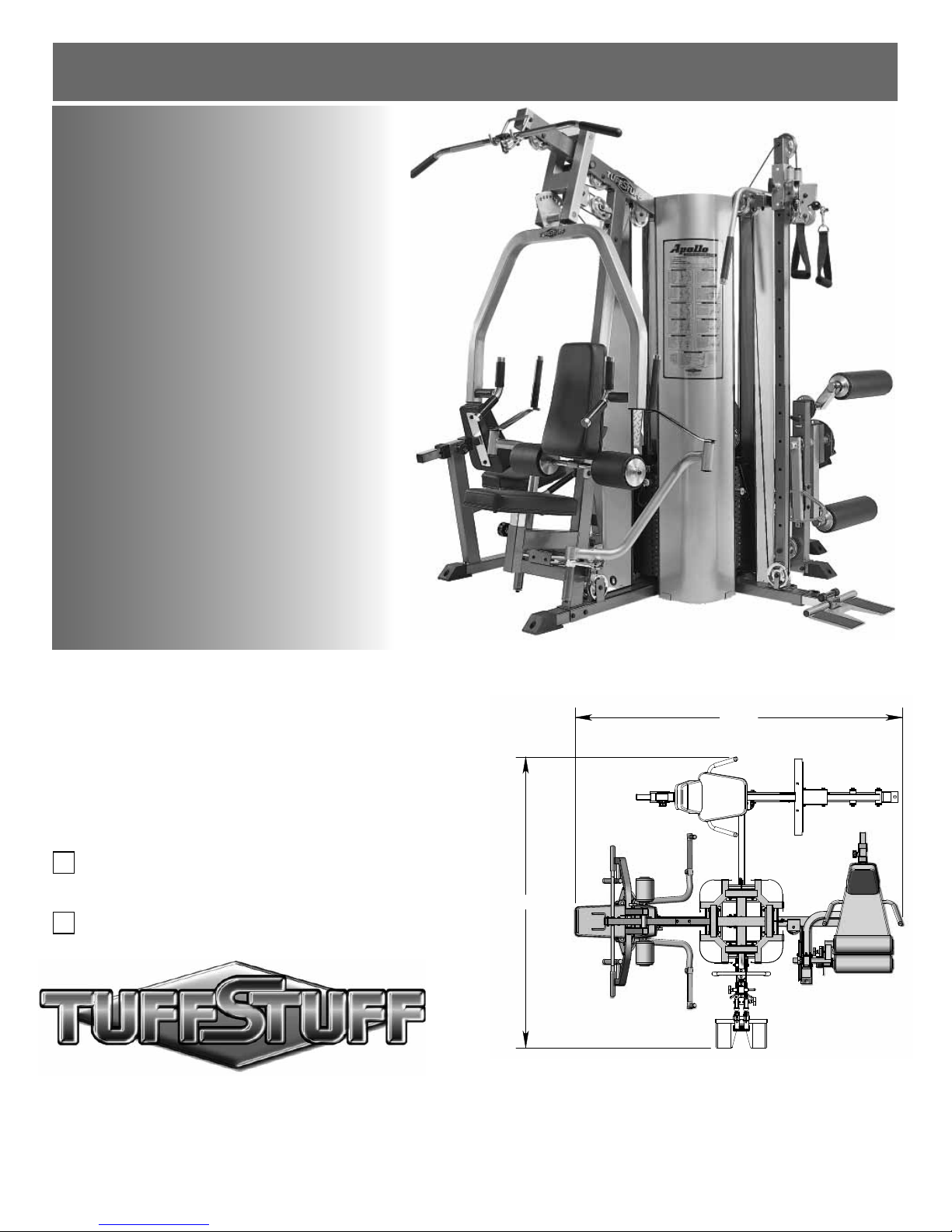
Apollo Modular Gym System
(Base Unit)
Standard
Deluxe
103"
91 1/2"
TuffStuff Fitness Equipment, Inc.
1325 E. Franklin Avenue
Pomona, CA 91766, USA
Ph: 909-629-1600 Fax: 909-629-4967
E-mail: service@tuffstuff.net Net: www.tuffstuff.net
AMERICA’S PREMIER EXERCISE EQUIPMENT
L 103” W 91 1/2” H 84
Apollo Base Unit Rev1
Revision Date 11-13-2007
Page 2
A
T
W
R
A
A
P
T
S
Introduction
T
bout the Apollo Modular Gym System
Congratulations on your new purchase of the Apollo Modular Gym
System. This gym is capable of a variety of different exercises, as
well as, smooth and user-friendly adjustment features. We hope
you are completely satisfied with this product and wish you many
years of enjoyment.
uff Stuff Equipment
This Tuffstuff product has been built to precise quality standards
and has been carefully packaged to ensure that damage will not
occur during shipment. The Limited Warranty and signature
indicating final inspection has been conducted by our line foreman,
is an expression of our confidence in the completeness, the
materials, and workmanship of this product.
arranty
SEE A COPY OF WARRANTY ON BACK PAGE.
egistration Card
To avoid unnecessary delays in warranty service and to insure that
a permanent record of your purchase is on file with our factory, be
sure to complete the warranty registration card and send it to
TuffStuff Fitness Equipment today.
pecifications
1. Maximum Wt. Capacity - 200 Lbs. Each Weight Stack
2. Total Machine Weight - 1575 Lbs.
3. Footprint (LWH) - See Front Cover
bout the Icons
The icons displayed in this Owner’s Manual are used to facilitate
the correct assembly and safe use of this Product, as-well-as to
prevent injury to yourself or anyone else.
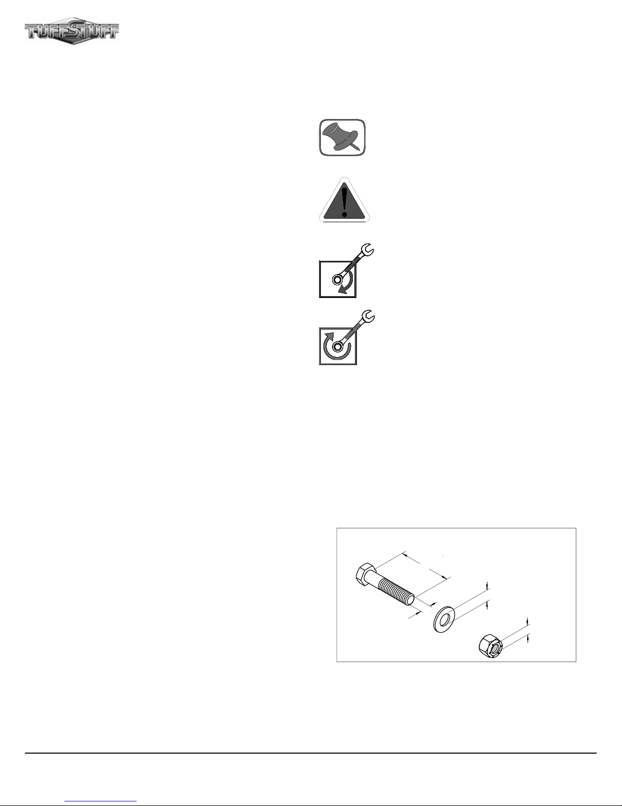
Note provides information necessary to properly
complete a procedure or information which will
make the procedure easier to understand.
Caution indicates a potentially hazardous situation, which, if not avoided, may result in minor or
moderate injury. It may also be used to alert
against unsafe practices.
Loosely Fasten provides a instruction to loosely
fasten (ex: hand tighten) a hardware assembly
only. This instruction is intended for the alignment
of hardware components during the assembly
process.
Fully Fasten provides a instruction to fully fasten
(ex: completely tighten) a hardware assembly.
rior to the Assembly of the Apollo Modular Gym System
1. We advise you to consult your local Tuff Stuff retailer if you
should have a question or problem regarding the proper
assembly of this Unit.
2. Consider the complete surface area of the Apollo Modular Gym
System. Use the overhead view on the front page for designing
your layout before assembling. Once the Apollo Modular Gym
System has been fully assembled it will be heavy and difficult to
move, therefore you should assemble the unit in the area where
it is to be used upon completion.
3. It is recommended that another person assist you with the
assembly of this unit.
ool Requirements
1. One 7/8” combination wrench
2. One 3/4” combination wrench
3. One 9/16” combination wrench
4. One 1/2” combination wrench
5. One ratchet
6. One 3/4” socket
7. One 9/16” socket
8. One 1/2” socket
9. One rubber mallet
10. One hammer
11. External retaining-ring pliers
12. Windex or household glass cleaner
13. One can silicone spray/ teflon spray lubricant
14. Multi-purpose grease
15. Measuring tape
16. Masking tape
17. Utility knife
1
ssembly Notes
1. Read and follow each step of this Assembly Instruction Manual in
sequence. Do not skip ahead, as it will result in an improper
assembly or in having to disassemble parts later.
2. During the assembly of this unit you will be instructed to leave
some Hex Head Cap Screws loosely fastened. Naturally, they
will be fully fastened later in the assembly process. This is done
to prevent any difficulty with alignment of some parts during the
assembly.
Hardware Measurement Diagram
H
G
N
E
L
W
E
R
SC
E
H
S
A
H
T
D
WI
W
E
R
C
S
Note: Due to continuing product improvements, specifications and designs are subject to change
without notice.
W
R
E
T
E
M
A
I
D
R
R
E
T
E
M
IA
D
T
U
N
Apollo Modular Gym System (Base Unit)
Page 3

S
Safety Precautions
afetyFirst
Regardless of how enthusiastic you may be about getting on
your equipment and exercising, take the time to ensure that
your safety is not jeopardized. A moment’s lack of attention
can result in an accident, as can failure to observe certain
simple safety precautions.
4. Use proper discretion when children are present.
5. Frayed or worn cables can be dangerous and may cause
injury. Periodically check these cables for any indication
of wear.
1. Read, study and understand the Assembly Instructions
and all the warning labels on this product. Furthermore, it
is recommended to familiarize yourself and others with the
proper operation and workout recommendations for this
Tuff Stuff product prior to use. Some of this information
can be obtained in this Assembly Instructions, as-well-as
from your local Tuff Stuff retailer.
2. It is imperative that you retain this Assembly Instructions
and be sure all warning labels are legible and intact.
Replacement Assembly Instructions and labels are
available from your local Tuff Stuff retailer.
3. Consult with your physician before beginning any exercise
program.
6. Keep hands, limbs, loose clothing and long hair well out of
the way of moving parts.
7. Do not attempt to lift more weight than you can control
safely.
8. Inspect the Unit for any sign of wear on parts, hardware
becoming loose or cracks on welds. If a problem is found
do not use or allow the machine to be used until the
defective part is repaired or replaced.
2Apollo Modular Gym System (Base Unit)
Page 4
C3
53
For the Single Column Station
no pulley needed here
53
B3
D6
B5
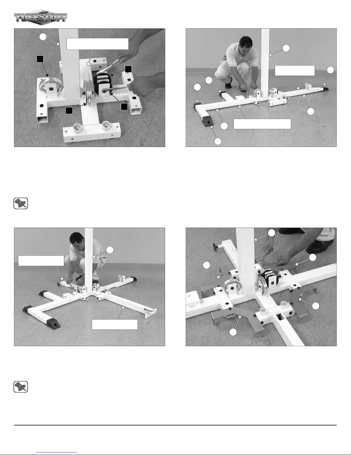
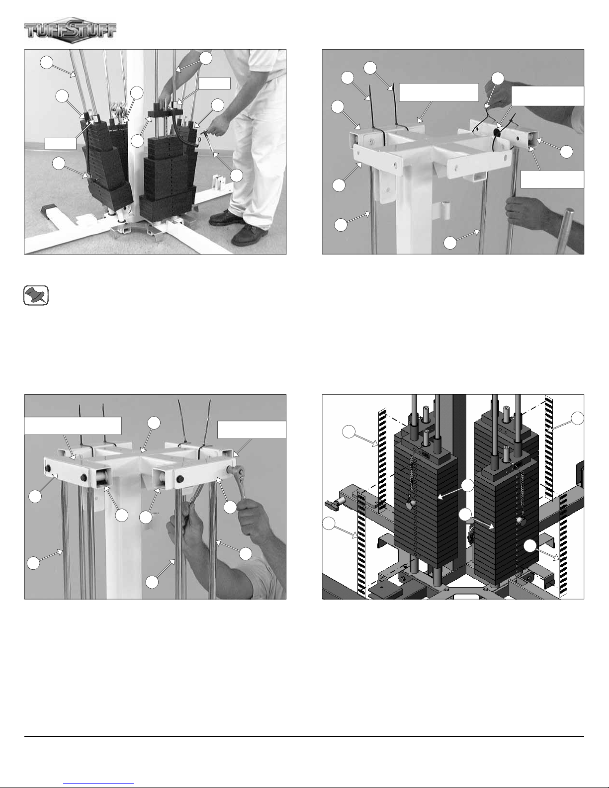
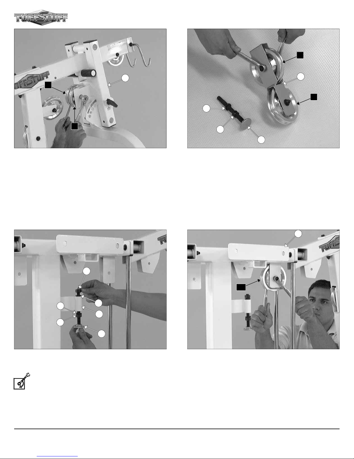
FIG. 1 Locate the Weight Stack Frame (#53) and attach two
Pulleys 4 1/2 Rd (#67-Labeled C3, D6) using two Hex Head Cap
Screws 3/8-16 X 1 3/4 (#97), four Flat Washers SAE 3/8” (#93), and
two Nylon Insert Jam Lock Nuts 3/8-16 (#118). Next, attach two
Pulleys 3 1/2 Rd (#66-Labeled B3, B5) to the Weight Stack Frame
(#53) brackets using one Hex Head Cap Screw 3/8-16 X 4 (#103), two
Flat Washers SAE 3/8” (#93), and one Nylon Insert Jam Lock Nut 3/816 (#118).
Note: The black boxed letters pointing to the pulleys are used
throughout this manual as reference to the Cable Mapping
Diagrams. These black boxed letters will be primarily used for
locating certain pulleys during the cable routing process.
122
122
122
122
Leg Extension/Curl Station
25
Press Bar Station
7
FIG. 2 Using a rubber mallet, insert one Plastic End Cap 2 X 3
(#122) onto the tube-end of the Bottom Connector Press Bar/Pec Fly
(#7), Next, insert three Plastic End Caps 2 X 3 (#122) onto the tubeends of the Leg Extension Bottom Frame (#25). Secure the Bottom
Connector Press Bar/Pec Fly (#7) and the Leg Extension Bottom
Frame (#25) to the Weight Stack Frame (#53), in the position as
shown above, using four Hex Head Cap Screws 3/8-16 X 3 1/4 (#101),
eight Flat Washers SAE 3/8 (#93), and four Nylon Insert Lock Nuts 3/816 (#119).
53
53
Single Column Station
Leg Press Station
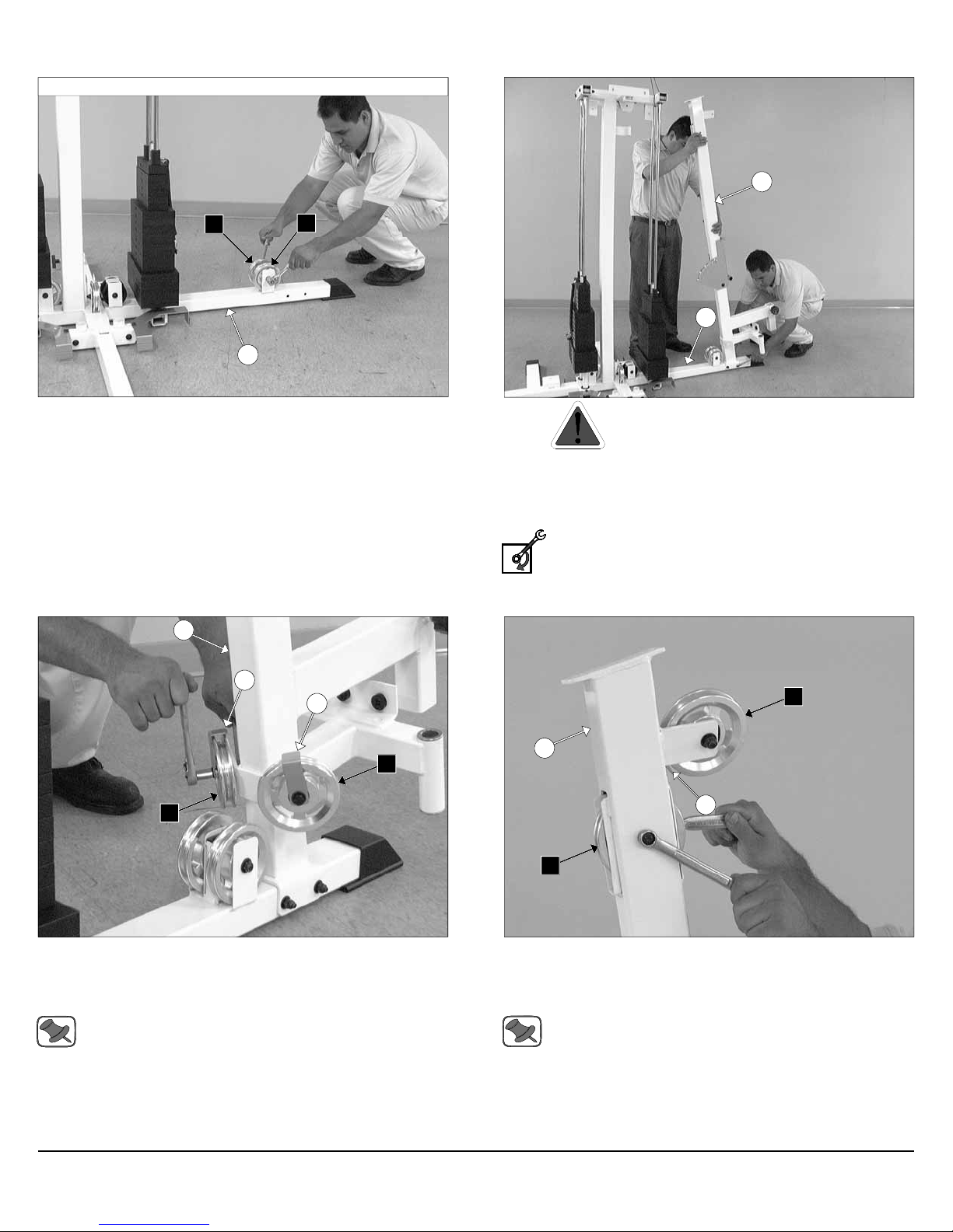
FIG. 3 Attach the Leg Press Bottom Connector and the Bottom
Upright Connector to the Weight Stack Frame (#53), in the position
as shown above, using four Hex Head Cap Screws 3/8-16 X 3 1/4
(#101), eight Flat Washers SAE 3/8 (#93), and four Nylon Insert Lock
Nuts 3/8-16 (#119).
Note: Depending on what optional Stations your system may include, the bottom connectors of these stations (Ab/Back, Inner
Outer Thigh, Multi-Press) can be attach to the Weight Stack
Frame (#53) as described above.
52
52
52
52
FIG. 4 Next, affix four Weight Shield Holders (#52) to the Weight
Stack Frame (#53) using eight Hex Head Cap Screws 3/8-16 X 3/4
(#102), and eight Nylon Insert Lock Nuts 3/8-16 (#119).
3 Apollo Modular Gym System (Base Unit)
Page 5
Assembly Instructions
10
10
136
136
136
136
Press Bar Station
Single Column
Station
92
92
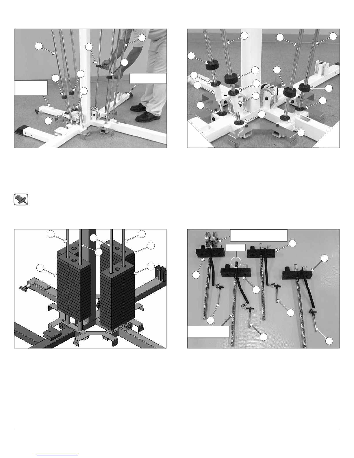
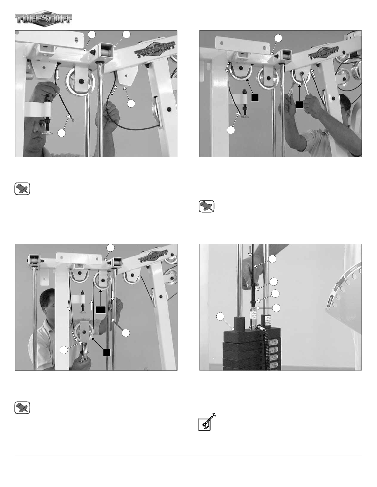
FIG. 5 Insert the eight Guide Rods (#10) into the receptacles of the
Weight Stack Frame (#53). Next, insert two Rubber Donuts (#136)
onto the Guide Rods (#10) located at the side of the Press Bar Station.
Next, on the side of the Single Column Station insert onto the Guide
Rods (#10) the following:
1. Two Flat Washers 3/4 X 2 (#92)
2. Two Rubber Donuts (#136)
Note: Lubricate the Guide Rods (#10) with a silcone or teflon
lubricant at this time.
136
92
54
92
10
136
92
54
10
136
92
10
136
92
Leg Extension
92
Leg Pre
FIG. 6 On the Leg Extension/Curl Station insert onto the Guide
Rods (#10) the following:
1. Two Flat Washers 3/4 X 2 (#92)
2. Two Weight Stack Spacers (#54)
3. Two Flat Washers 3/4 X 2 (#92)
4. Two Rubber Donuts (#136)
On the Leg Press Station insert onto the Guide Rods (#10) the following:
1. Two Flat Washers 3/4 X 2 (#92)
2. Two Rubber Donuts (#136)
s
s
56
10
10
10
10
56
56
FIG. 7 Carefully begin sliding the nineteen (19) 10 Lb. Weight
Plates (#56) over the Guide Rods (#10). Repeat the same process for
the other three stations.
Assembled to be used on
the Single Pulley Station
No Label
58
58
31
58
58
31
To be used on the
Leg Press Station
31
31
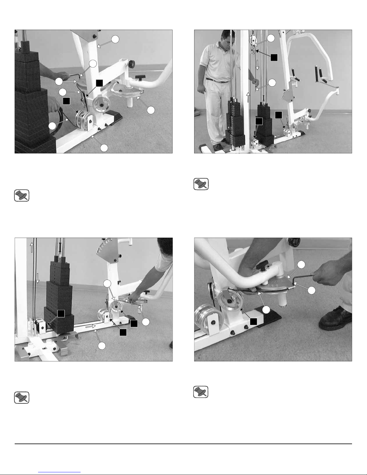
FIG. 8 Locate the four Top Plate Selector Bars (#58) and assemble
Magnetic Selector Pins W/Coil 3/8 X 4 (#31) in the position as shown
above.
Apollo Modular Gym System (Base Unit)
4
Page 6
10
58
58
10
LABEL
58
17
127
127
Single Column Station
127
Lat Cable will route
through this hole
LABEL
31
58
31
FIG. 9 Assemble each Top Plate/Selector Bar (#58) to its corresponding workstation
Note: Be sure the Label and the Selector Pin w/Coil (#31) located on each Top Plate/Selector Bar (#58) are facing out, before sliding the Top Plate/Selector Bars (#58) onto the Guide
Rods (#10).
Leg Extension/Curl Station
53
Leg Press Station
18
53
10
10
Press Bar Station
FIG. 10 On the Single Column Station, maneuver the two Guide
Rods (#10) into the bottom holes of a Guide Rod Retainer (#17).
Next, temporary secure the Guide Rod Retainer (#17) to the Weight
Stack Frame (#53) using two Plastic Ties (#127).
Next, locate the Press Bar Station Guide Rod Retainer (#18) and attach it to the side of the Press Bar Station following the previous procedure.
85
85
43
43
10
10
17
17
10
FIG. 11 On the side of the Leg Extension/Curl Station, maneuver the
two Guide Rods (#10) into the bottom holes of a Guide Rod Retainer
(#17). Next, secure the Guide Rod Retainer (#17) to the Weight
Stack Frame (#53) using one Reinforcement Plate 1/4 X 2 X 8 1/2
(#43), two Hex Head Cap Screws 3/8-16 X 3 1/4 (#101), four Flat
Washers SAE 3/8” (#93), and two Nylon Insert Lock Nuts 3/8-16
(#119).
Next, repeat the same procedure for the Leg Press Station.
5
56
56
85
85
FIG. 12 Attach the Decal Weight Numbers (#85) to the Weight
Plates (#56).
Apollo Modular Gym System (Base Unit)
Page 7
Assembly of the Press Bar Station Fig. 13 - Fig. 48
Assembly Instructions
16
B2
7
FIG. 13 Attach two Pulleys 4 1/2 Rd. (#67-Labeled B2, B6) to the
Press Bar Station Base Frame (#7) pulley brackets using one Hex
Head Cap Screw 3/8-16 X 4 (#103), two Flat Washers SAE 3/8 (#93),
and one Nylon Insert Jam Lock Nut 3/8-16 (#118).
16
B6
7
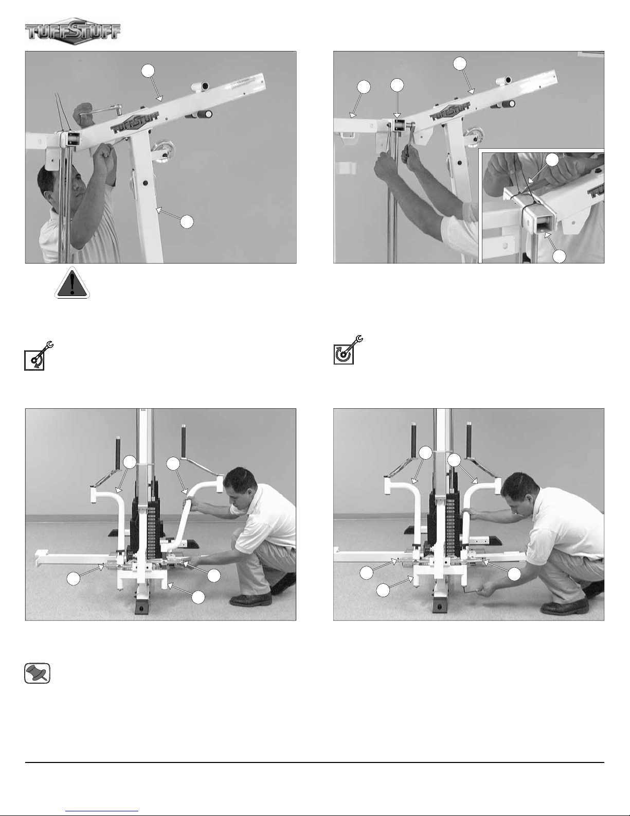
FIG. 14 Caution: It is strongly recommended to use another
person in assisting with this assembly.
Attach the Front Upright (#16) to the Bottom Connector Press Bar/
Pec Fly (#7) using two Hex Head Cap Screws 3/8-16 X 4 1/4 (#104),
four Flat Washers SAE 3/8” (#93), and two Nylon Insert Lock Nuts 3/816 (#119).
Loosely Fasten: Do not completely fasten this hardware
assembly until assembling the Top Pulley Assembly (#49) to
the Press Bar Station Guide Rod Retainer (#18) described in
FIG. 18.
8
8
B7
B1
FIG. 15 Attach two Pulleys 4 1/2 Rd (#67-Labeled B1, B7) and two
Cable Retainer Brackets (#8) to the Front Upright (#16) using two
Hex Head Cap Screws 3/8-16 X 2 (#98), four Flat Washers SAE
3/8” (#93), and two Nylon Insert Lock Nuts 3/8-16 (#119).
Note: Be sure the Cable Retainer Brackets (#8) are positioned
as shown above.
A4
16
8
A6
FIG. 16 Next, attach a Pulley 4 1/2 Rd (#67-Labeled A4) and a Cable Retainer Bracket (#8) to the plate of the Front Upright (#16) using
one Hex Head Cap Screw 3/8-16 X 2 (#98), two Flat Washers SAE
3/8” (#93), and one Nylon Insert Lock Nut 3/8-16 (#119).
Note: Be sure the Cable Retainer Bracket (#8) is positioned as
shown above.
Next, attach another Pulley 4 1/2 Rd (#67-Labeled A6) to the Front Upright (#16) using one Hex Head Cap Screw 3/8-16 X 2 1/2 (#99), two
Flat Washers SAE 3/8” (#93), and one Nylon Insert Jam Lock Nut 3/816 (#118).
Apollo Modular Gym System (Base Unit)
6
Page 8
49
16
FIG. 17 Caution: It is strongly recommended to use another
person in assisting with this assembly.
Attach the Top Pulley Assembly (#49) to the Front Upright (#16)
using two Hex Head Cap Screws 3/8-16 X 4 1/4 (#104), four Flat
Washers SAE 3/8” (#93), and two Nylon Insert Lock Nuts 3/8-16
(#119).
Loosely Fasten: Do not completely fasten this hardware
assembly at this time.
49
53
18
127
18
FIG. 18 Using a utility knife, remove the two Plastic Ties (#127) from
the Press Bar Station Guide Rod Retainer (#18).
Next, affix the Top Pulley Assembly (#49) to the Press Bar Station
Guide Rod Retainer (#18) and the Weight Stack Frame (#53) using
two Hex Head Cap Screws 3/8-16 X 3 1/4 (#101), four Flat Washers
SAE 3/8” (#93) and two Nylon Insert Lock Nuts 3/8-16 (#119).
Fully Fasten: Proceed to align and fully fasten this hardware
assembly and the previous assemblies that were left loosely
fastened. (Assemblies described in FIG. 14 and FIG. 17).
36
60
35
60
16
FIG. 19 Insert the Left Pec Dec Arm (#35) along with the Aluminum Cam Plate (#60) into the receptacle of the Front Upright (#16).
Repeat the same procedure for the Right Pec Dec Arm (#36).
Note: It is recommended to grease both axles of the Left and
Right Pec Dec Arms (#35, #36) with multi-purpose grease prior
to assembling.
15
16
119
8
119
FIG. 20 Secure the Left Pec Dec Arm (#35) into place using one
Button Head Socket Cap Screw 3/8-16 X 1 (#71), one Split Lock
Washer 3/8” (#152), and one Chrome Washer 3/8 X 1 1/2 (#74).
Repeat the same procedure for the Right Pec Dec Arm (#36).
7
Apollo Modular Gym System (Base Unit)
Page 9
Assembly Instructions
49
21
A1
FIG. 21 Next, attach a Pulley 4 1/2 Rd (#67-Labeled A1) to the Top
Pulley Assembly (#49) using one Hex Head Cap Screw 3/8-16 X 2 1/2
(#99), two Flat Washers SAE 3/8” (#93), and one Nylon Insert Jam
Lock Nut 3/8-16 (#118). Next, attach the Lat Bar Holder 2 X 3 (#21) to
the Top Pulley Assembly (#49) using one Hex Head Cap Screw 3/816 X 2 3/4 (#100), two Flat Washers SAE 3/8” (#93), and one Nylon
Insert Jam Lock Nut 3/8-16 (#118).
39
49
41
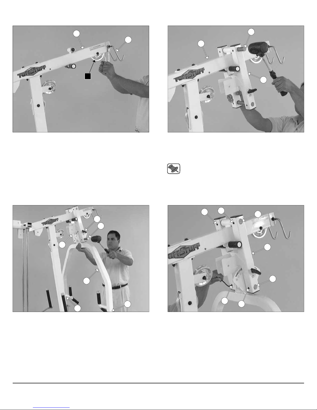
FIG. 22 Using a rubber mallet, insert one Pivot Axle 1 X 8 1/8 (#39)
through the holes of the Press Bar Selector Housing (#41) and
through the receptacle of the Top Pulley Assembly (#49) until the
Pivot Axle 1 X 8 1/8 (#39) is flush with both sides of the Press Bar
Selector Housing (#41).
Note: It is recommended to grease the Pivot Axles 1 X 8 1/8
(#39) with multi-purpose grease prior to assembling.
130
39
41
42
126
126
FIG. 23 Using a rubber mallet, insert two Plastic Insert Caps 2” Sq.
(#126) into the tube-ends of the Press Bar (#42). Next, insert the
Press Bar (#42) up into the Press Bar Selector Housing (#41) and
support in into place using the Pull Pin 1/2 X 3 1/2 (#130). Next, using
a rubber mallet, insert the Pivot Axle 1 X 8 1/8 (#39) into the Press
Bar Selector Housing (#41) and through the Press Bar (#42).
150
150
150
39
41
39
150
FIG. 24 Secure the two Pivot Axles 1 X 8 1/8 (#39) to the Press Bar
Selector Housing (#41) using four Set Screws 3/8-16 X 1/2 (#150).
Use the Supplied Hex Key 3/16” (#107) for securing these Set Screws
3/8-16 X 1/2 (#150) into the threaded sockets on the Press Bar
Selector Housing (#41). Next, clean the ends of the Pivot Axles 1 X
8 1/8 (#39) and apply four 1” Rd. Silver Mylar Decals (#77–Not shown).
These decals are used to hide and protect the ends of the axles.
Apollo Modular Gym System (Base Unit)
8
Page 10
A9
41
A3
A5
FIG. 25 Next, attach two Pulleys 4 1/2 Rd. (#67-Labeled A3, A5) to
the Press Bar Selector Housing (#41) using one Hex Head Cap
Screw 3/8-16 X 2 3/4 (#100), two Flat Washers SAE 3/8” (#93), and
one Nylon Insert Jam Lock Nut 3/8-16 (#118).
12
B4
153
88
30
FIG. 26 Locate the Closed-end Double Pulley Bracket (#12) and
attach two Pulleys 4 1/2 Rd. (#67-Labeled A9, B4) using two Hex Head
Cap Screws 3/8-16 X 1 3/4 (#97), four Flat Washers SAE 3/8” (#93),
and two Nylon Insert Jam Lock Nuts 3/8-16 (#118). Next, thread one
Finished Hex Nut 1/2-13 (#88) and insert one Split Lock Washer
1/2” (#153) onto the Adjustable Stopper (#30).
1
88
153
88
153
53
30
FIG. 27 Next, attach the Adjustable Stopper (#30) to the receptacle
of the Weight Stack Frame (#53) using one Split Lock Washer
1/2” (#153) and one Finished Hex Nut 1/2-13 (#88).
Loosely Fasten: Do not completely fasten this hardware assembly at this time, as it will be completely fasten once the cables have been adjusted.
9
A10
FIG. 28 Next, attach a Pulley 4 1/2 Rd. (#67-Labeled A10) to the
Weight Stack Frame (#53) using one Hex Head Cap Screw 3/8-16 X 1
3/4 (#97), two Flat Washers SAE 3/8” (#93), and one Nylon Insert Jam
Lock Nut 3/8-16 (#118).
Apollo Modular Gym System (Base Unit)
Page 11

Assembly Instructions
49
A1
22
FIG. 29 Begin routing the Lat Cable (#22) up and over the Pulley 4
1/2 Rd. (#67-Labeled A1) and into the tube of the Top Pulley
Assembly (#49). Then, pull the Lat Cable (#22) down through the
opening at the bottom of the Top Pulley Assembly (#49).
Note: Refer to the Cable Mapping Diagram on fold-out page 21
for further detailed illustration of the Lat Cable (#22) routing.
49
A2
22
FIG. 30 Insert a Pulley 4 1/2 Rd. (#67-Labeled A2) into the slot at
the bottom of the Top Pulley assembly (#49) and secure it into place
using one Hex Head Cap Screw 3/8-16 X 2 1/2 (#99), two Flat Washers
SAE 3/8” (#93), and one Nylon Insert Jam Lock Nut 3/8-16 (#118). Be
sure the cable is routed properly into the groove of the Pulley.
Note: Refer to the Cable Mapping Diagram on fold-out page 21
for further detailed illustration of the Lat Cable (#22) routing.
A3
41
22
A4
16
FIG. 31 Next, continue to route the Lat Cable (#22) around the
Pulley 4 1/2 Rd. (#67-Labeled A3), then across and over the Pulley 4
1/2 Rd. (#67-Labeled A4).
Note: Refer to the Cable Mapping Diagram on fold-out page 21
for further detailed illustration of the Lat Cable (#22) routing.
41
22
A6
A5
16
FIG. 32 Next, continue to route the Lat Cable (#22) over the Pulley 4
1/2 Rd. (#67-Labeled A5), then through the Front Upright (#16) and
under the Pulley 4 1/2 Rd. (#67-Labeled A6).
Note: Refer to the Cable Mapping Diagram on fold-out page 21
for further detailed illustration of the Lat Cable (#22) routing.
Apollo Modular Gym System (Base Unit)
10
Page 12
53 18
53
49
22
FIG. 33 Route the Lat Cable (#22) passing through the openings of
the Top Pulley Assembly (#49), the Press Bar Station Guide Rod
Retainer (#18), and the Weight Stack Frame (#53).
Note: Refer to the Cable Mapping Diagram on fold-out page 21
for further detailed illustration of the Lat Cable (#22) routing.
53
A8
A7
22
FIG. 34 Insert two Pulleys 4 1/2 Rd. (#67-Labeled A7, A8) into the
pulley brackets of the Top Pulley assembly (#49) and the Weight
Stack Frame (#53). Secure the pulleys into place using two Hex Head
Cap Screws 3/8-16 X 1 3/4 (#97), four Flat Washers SAE 3/8” (#93),
and two Nylon Insert Jam Lock Nuts 3/8-16 (#118). Be sure the cable
is routed properly into the groove of the pulleys.
Note: Refer to the Cable Mapping Diagram on fold-out page 21
for further detailed illustration of the Lat Cable (#22) routing.
22
A10
22
12
A9
FIG. 35 Next, locate the Closed-End Double Pulley Bracket (#12)
and continue to route the Lat Cable (#22) down and under the Pulley 4
1/2 Rd. (#67-Labeled A9), then route up and over the Pulley 4 1/2 Rd.
(#67-Labeled A10).
Note: Refer to the Cable Mapping Diagram on fold-out page 21
for further detailed illustration of the Lat Cable (#22) routing.
151
88
153
58
FIG. 36 Attach one Split Hex Tap Bolt 1/2-13 X 3 1/2 (#151) to the
Lat Cable (#22). Then, thread one Finished Hex Nut 1/2-13 (#88) and
insert one Split Lock Washer 1/2” (#153) to the Split Hex Tap Bolt 1/213 X 3 1/2 (#151).
Next, thread the Split Hex Tap Bolt 1/2-13 X 3 1/2 (#151) to the Top
Plate Selector Bar (#58).
Loosely Fasten: Do not completely fasten this hardware assembly at this time, as it will be completely fasten later in the
assembly process to obtain proper cable tension.
11
Apollo Modular Gym System (Base Unit)
Page 13
Assembly Instructions
16
146
60
8
B1
B2
60
37
7
FIG. 37 Attach one end of the Pec Dec Cable (#37) to the Aluminum Cam Plate (#60) and secure it onto place using one Socket Head
Cap Screw 1/4-20 X 3/4 (#146). Next, route the Pec Dec Cable (#37)
over the Pulley 4 1/2 Rd. (#67-Labeled B1), and then under the Pulley 4
1/2 Rd. (#67-Labeled B2).
Note: Refer to Fig. C on fold-out page 21 for further clarification
of this hardware assembly.
12
B4
37
B2
B3
FIG. 38 Continue routing the Pec Dec Cable (#37) under the weight
stack and the Pulley 3 1/2” Rd. (#66-Labeled B3), and then up and over
the Pulley 4 1/2” Rd. (#67-Labeled B4).
Note: Refer to the Cable Mapping Diagram on fold-out page 21
for further detailed illustration of the Pec Dec Cable (#37)
routing.
8
B5
137
B7
B6
7
FIG. 39 Route the Pec Dec Cable (#37) down and under the Pulley
3 1/2” Rd. (#66-Labeled B5). Next, route the cable to the Pulley 4 1/2”
Rd. (#67-Labeled B6), and then up and over the Pulley 4 1/2” Rd. (#67Labeled B7).
Note: Refer to the Cable Mapping Diagram on fold-out page 21
for further detailed illustration of the Pec Dec Cable (#37)
routing.
60
146
37
B7
FIG. 40 Next, attach the end of the Pec Dec Cable (#37) to the Aluminum Cam Plate (#30) and secure it into place using one Socket
Head Cap Screw 1/4-20 X 3/4 (#146).
Note: Refer to Fig. C on fold-out page 21 for further clarification
of this hardware assembly.
Apollo Modular Gym System (Base Unit)
12
Page 14

123
4
4
6
6
156
16
FIG. 41 Using a rubber mallet, insert one Plastic Insert Cap 1 3/4
(#123) into the tube-end of the Bench Press Adjustable Seat Frame
(#4). Next, attach the Bench Press Adjustable Seat Frame (#4) to
the Bench Press Seat Pad (#6) using two Hex Head Cap Screws 3/816 X 1 1/4 (#96), and two Flat Washers SAE 3/8” (#93).
2
15
147
FIG. 42 Attach the assembled Bench Press Adjustable Seat
Frame (#4) to the Front Upright (#16).
15
13
13
FIG. 43 Next, insert the Foot Roll Tube 1 X 27 (#15) into the
receptacle of the Adjustable Back Pad Bracket (#2). Use a measuring tape to center the Foot Roll Tube 1 X 27 (#15) to the Adjustable
Back Pad Bracket (#2). Next, secure the Foot Roll Tube 1 X 27 (#15)
to the Adjustable Back Pad Bracket (#2) using one Set Screw 1/4-20
X 1/4 (#147).
13
FIG. 44 Insert two Foam Rolls 1 X 5 1/2 X 7 1/4 (#13) to the tubeends of the Foot Roll Tube 1 X 27 (#15) and secure them into place
using two Button Head Socket Cap Screws 3/8-16 X 1 (#71), two Split
Lock Washers 3/8” (#152), and two Chrome Washers 3/8 X 1 1/2 (#74).
Apollo Modular Gym System (Base Unit)
Page 15

135
Assembly Instructions
113
113
2
FIG. 45 Attach two Metal Hinges (#113) to the axle of the
Adjustable Back Pad Bracket (#2). Be sure to position the Metal
Hinges (#117) as shown above.
113
5
113
2
FIG. 46 Attach a Rubber Bumper 3/8 X 1 1/2 (#135) to the Bench
Press Back Pad (#5) using one Hex Head Cap Screw 3/8-16 X 1 1/2
(#95). Next, attach the Bench Press Back Pad (#5) to the Metal
Hinges (#113) using two Hex Head Cap Screws 3/8-16 X 1 1/4 (#96),
and two Flat Washers SAE 3/8” (#93).
139
139
112
139
139
111
FIG. 47 Insert a Rubber Grip (#139) over each one of the tube-ends
of the Low Row Bar 20” (#112) and the Lat Bar 48” (#111), as shown
above.
Note: To facilitate the insertion of these Rubber Grips, use Windex or household glass cleaner.
21
111
75
145
FIG. 48 Next, attach one Snap Link (#145) to the Clevis Bracket
(#75) using one Shoulder Bolt 3/8 X 3/4 (#144), and one Nylon Insert
Lock Nut 5/16-18 (#120). Use the supplied Hex Key 3/16” (#107) and a
1/2” combination wrench to fasten this assembly properly.
Note: Refer to Fig. A on fold-out page 21 for further clarification
of this hardware assembly.
Connect the Lat Bar 48” (#111) to the Lat Cable (#22) using the Snap
Link (#145). Rest the Lat Bar 48” (#111) onto the Lat Bar Holder
(#21), when not in use.
Apollo Modular Gym System (Base Unit)
14
Page 16

Assembly of the Leg Ext / Leg Curl Station Fig. 49 - Fig. 65
25
C2
27
25
FIG. 49 Attach a Pulley 4 1/2” Rd. (#67-Labeled C2) to the Leg Extension Bottom Connector (#25) using one Hex Head Cap Screw 3/8-
16 X 1 3/4 (#97), two Flat Washers SAE 3/8” (#93), and one Nylon Insert Jam Lock Nut 3/8-16 (#118).
11
38
27
38
29
116
11
FIG. 50 Next, attach the Leg Extension Front Frame (#27) to the
Leg Extension Bottom Connector (#25) using two Hex Head Cap
Screws 3/8-16 X 4 1/4 (#104), four Flat Washers SAE 3/8” (#93), and
two Nylon Insert Lock Nuts 3/8-16 (#119).
11
134
1
1
11
FIG. 51 Insert a Nylon Flat Washer 1 X 1 1/4 (#116) onto the axle of
the Circular Plate (#11).
Note: Lubricate the axle of the Circular Plate (#11) with multipurpose grease at this time.
Next, insert the axle of the Circular Plate (#11) into the receptacle of
the Pivot Arm (#38). Then, insert the axle of the Circular Plate (#11)
with the captive Pivot Arm (#38) into the bearing housing of the Leg
Extension Front Frame (#27).
15
FIG. 52 Attach the Actuator Arm (#1) to the axle of the Circular Plate
(#11). Next, align the hole of the Actuator Arm (#1) to the hole of the
Circular Plate with Axle (#11) and, using a hammer, insert the Roll Pin
3/8 X 1 1/2 (#151).
Apollo Modular Gym System (Base Unit)
Page 17

C1
Assembly Instructions
126
27
8
FIG. 53 Next, attach one Pulley 4 1/2 Rd. (#67-Labeled C1) and one
Cable Retainer Bracket (#8) to the Leg Extension Front Frame (#27)
using one Hex Head Cap Screw 3/8-16 X 4 1/4 (#104), one Flat
Washer SAE 3/8” (#93), and one Nylon Insert Lock Nut 3/8-16 (#119).
28
25
FIG. 54 Using a rubber mallet, insert one Plastic Insert Cap 2” Sq.
(#126) into the tube-end of the Leg Extension Seat Frame (#28).
Next, attach the Leg Extension Seat Frame (#28) to the Leg
Extension Bottom Connector (#25) using two Hex Head Cap Screws
3/8-16 X 4 1/4 (#104), four Flat Washers SAE 3/8” (#93), and two Nylon
Insert Lock Nuts 3/8-16 (#119).
Loosely Fasten: Do not completely fasten this hardware
assembly until assembling the Leg Extension Arm Support
(#23). (Assembly described in FIG. 55).
23
28
27
25
FIG. 55 Next, attach the Leg Extension Arm Support (#23) to the
Leg Extension Front Frame (#27) using two Hex Head Cap Screws
3/8-16 X 4 1/4 (#104), four Flat Washers SAE 3/8” (#93), and two Nylon
Insert Lock Nuts 3/8-16 (#119). Next, attach the other end of the Leg
Extension Arm Support (#23) to the Leg Extension Seat Frame
(#28) using two Hex Head Cap Screws 3/8-16 X 3 1/4 (#101), four Flat
Washers SAE 3/8” (#93), and two Nylon Insert Lock Nuts 3/8-16
(#119).
Fully Fasten: Proceed to align and fully fasten this hardware
assembly and the assembly described in FIG. 54.
Apollo Modular Gym System (Base Unit)
20
19
28
FIG. 56 Attach the Left Handle (#19) and the Right Handle (#20) to
the Leg Extension Seat Frame (#28), in the position as shown above,
using two Hex Head Cap Screws 3/8-16 X 3 1/4 (#101), four Flat
Washers SAE 3/8” (#93), and two Nylon Insert Lock Nuts 3/8-16
(#119).
16
Page 18

29
123
3
24
28
FIG. 57 Attach Leg Extension Seat Pad (#29) to the Leg Extension
Seat Frame (#28) using four Hex Head Cap Screws 3/8-16 X 1 1/4
(#96), and four Flat Washers SAE 3/8” (#93).
24
156
3
28
FIG. 58 Using a rubber mallet, insert one Plastic Insert Cap 1 3/4”
Sq. (#123) into the tube-end of the Back Pad Adjustable Tube (#3).
Next, attach the Back Pad Adjustable Tube (#3) to the Leg Exten-
sion Back Pad (#29) using two Hex Head Cap Screws 3/8-16 X 1 1/4
(#96), and two Flat Washers SAE 3/8” (#93).
27
48
38
47
FIG. 59 Insert the assembled Back Pad Adjustable Tube (#3) to the
Leg Extension Seat Frame (#28).
17
FIG. 60 Next, attach the Top Adjustable Leg Holder Tube (#48) to
the Leg Extension Front Frame (#27) using one Button Head Socket
Cap Screw 3/8-16 X 1 (#71), one Split Lock Washer 3/8” (#152), and
one Chrome Washer 3/8 X 1 1/2 (#74). Next, attach the Swivel Foam
Roll Tube (#47) to the Pivot-Arm (#38) using one Button Head Socket
Cap Screw 3/8-16 X 1 (#71), one Split Lock Washer 3/8” (#152), and
one Chrome Washer 3/8 X 1 1/2 (#74).
Apollo Modular Gym System (Base Unit)
Page 19

Assembly Instructions
48
47
14
14
FIG. 61 Next, attach two Foam Rolls 2 X 5 1/2 X 18 (#14) to the Top
Adjustable Leg Holder Tube (#48) and the Swivel Foam Roll Tube
(#47) using two Button Head Socket Cap Screws 3/8-16 X 1 (#71), two
Split Lock Washers 3/8” (#152), and two Aluminum Washers 3/8 X
2.584 OD (#68).
C4
53
FIG. 62 Attach a Pulley 4 1/2” Rd. (#67-Labeled C4) to the Weight
Stack Frame (#53) pulley bracket using one Hex Head Cap Screw 3/8-
16 X 1 3/4 (#97), two Flat Washers SAE 3/8” (#93), and one Nylon Insert Jam Lock Nut 3/8-16 (#118).
1
26
8
C1
FIG. 63 Attach the looped-end of the Leg Extension Cable (#26) to
the bracket of the Actuator Arm (#1) using one Shoulder Bolt 3/8 X 3/4
(#144), and one Nylon Insert Lock Nut 5/16-18 (#120). Next, route the
Leg Extension Cable (#26) under the Pulley 4 1/2 Rd. (#67-Labeled
C1).
Note: Refer to the Cable Mapping Diagram on fold-out page 26
for further detailed illustration of the Leg Extension Cable (#26)
routing.
C4
26
C3
C2
FIG. 64 Continue routing the Leg Extension Cable (#26) around the
Pulley 4 1/2 Rd. (#67-Labeled C2). Next, route under the Pulley 4 1/2
Rd. (#67-Labeled C3), and then up and over the Pulley 4 1/2 Rd. (#67Labeled C4).
Note: Refer to the Cable Mapping Diagram on fold-out page 26
for further detailed illustration of the Leg Extension Cable (#26)
routing.
Apollo Modular Gym System (Base Unit)
18
Page 20

26
151
FIG. 65 Attach one Split Hex Tap Bolt 1/2-13 X 3 1/2 (#151) to the
Leg Extension Cable (#26). Then, thread one Finished Hex Nut 1/2-
13 (#88) and insert one Split Lock Washer 1/2” (#153) to the Split Hex
Tap Bolt 1/2-13 X 3 1/2 (#151).
Next, thread the Split Hex Tap Bolt 1/2-13 X 3 1/2 (#151) to the Top
Plate Selector Bar (#58).
88
58
153
Leg Press Station Ab/Back Station Ab/Back Station
Single Column Station
Inner Outer Thigh Station
FIG. 66 Proceed to Assemble two of the four optional attachments to the sides of the unit.
19
Inner Outer Thigh Station
Apollo Modular Gym System (Base Unit)
Page 21

Assembly Instructions
FIG. 67 Before assembling the Weight Shields
(#50 & #51), inspect and adjust the cables to ensure
a safe and smooth operation.
50
50
52
52
FIG. 68 Insert one of the Weight Shields (#50) to one of the bottom
Weight Shield Holder (#52) as shown above
Note: Refer to the illustrations shown on fold-out page 28 for further clarification of this hardware assembly.
52
Guide Rod Retainer
17
50
50
52
FIG. 69 Next, insert one Weight Shield Holder (#52) to the top of the
Weight Shield (#50). Next, secure the Weight Shield Holder (#52)
along with the Weight Shield (#50) to the two adjacent Guide Rod Retainers (#17) using two Hex Head Cap Screws 3/8-16 X 3/4 (#102), and
two Nylon Insert Lock Nuts 3/8-16 (#119).
Repeat the same process for the three other Weight Shields (#50).
Note: Refer to the illustrations shown on fold-out page 28 for further clarification of this hardware assembly.
Apollo Modular Gym System (Base Unit)
28
Page 22

Maintenance
TuffStuff Basic Strength Equipment Safety and General Maintenance
All TUFFSTUFF strength equipment is designed and manufactured to offer maximum, long-life service
with minimal maintenance. However, safety inspection and routine maintenance in your facility should be
the upmost importance in your daily operation. Information presented in these pages will serve as a basic
guideline to design your own inspection procedures.
Part One: General Inspection and Cleaning
Equipment should be wiped down with a damp cloth and dried on a daily basis. The powder coat fi nish
should be polished with a good car wax on a monthly basis. A daily wipe down of the upholstery with a lanolin based hand cleaner or Naugahyde Cleaner. Do not use cleaners such as Lysol or Windex as they will
dry out and crack the vinyl. Lanolin hand cleaner dissolves the sweat and lubricates the vinyl, maintaining
its natural fl exibility. Sweat is corrosive and when left on the frame and components will eventually cause
corrosion or rust. When performing these cleaning sessions, it is the perfect time to inspect the equipment
and note any problems for the maintenance personnel to correct.
1. Check equipment if it is operating properly.
2. Check the cable for loose fi ttings or frayed cable and is seating properly on the pulleys and
cams.
3. Make sure that the proper weight stack selector pin is with each machine and that the pin functions properly.
4. If something appears loose be sure to have it tightened immediately.
5. If a piece of equipment appears damaged or not operation properly, place the piece out-of-service immediately.
Part Two: Maintenance
In this paragraph, we will discuss the inspection of the cables, pulleys and their associated components. If
there exists the potential for injury to occur on a machine, it will most likely lie in the cable system. It is important to inspect the cables frequently and let it be known to all users that it is their responsibility to report
any worn-out cable to prevent a sudden failure that can result in an injury. Cables are moving parts, meaning cable-wear will occur regardless of the type or size used. In the advent of the 3/16” mill-spec cable this
wear takes longer to become apparent and this is why frequent inspections are so important.
1. Check the cable termination at the weight stack. To perform any cable tension adjustment,
loosen the hex jam nut and thread the hex tap bolt in or out to give cable the proper tension.
Re-tightened the hex jam nut when adjustment is complete and make sure the hex tap bolt is
threaded 1/2” into the socket of the selector bar top plate.
2. Check the cable as it terminates at the cam. Check the end fi tting for any signs of fraying in this
area. Inspect the bolt and nut and/or screw holding the fi tting and be sure that it is tight.
3. Check the cables as it passes over all pulley wheels. Visually inspect the cables and pulleys. A
cable that is wearing will exhibit a ballooned surface that passes over the pulley. This is and early
warning sign to replace the cable.
29
Apollo Modular Gym System (Base Unit)
Page 23

Maintenance
Part Three: Lubrication
Bearing and linear bearings systems have advanced over the years but they must be maintained on a regular basis if you expect them to last and perform effi ciently. TuffStuff uses only the highest quality bearings
and linear motion components that are virtually trouble-free but requires the regular preventive maintenance
to insure long-lasting performance.
1. Bronze and nylon bushings, we recommend on a monthly basis to spray a tefl on-base lubricant
(silicone-free) directly onto the shaft as it passes through these bushings. Spray a small amount
onto the shaft and rotate it through its complete movement and wipe off any excess.
2. Weight stack guide rods and bushings, again use tefl on spray lubricant and this time spray onto
a rag and wipe the guide rods down with this rag on a weekly basis. Do not use WD-40 or other
lubricants as they attract dirt and will crate a mess between the weight plates and bushings.
3. Sealed bearings pivot points, as the name implies are protected from the outside environment
and require no lubrication. During the machine wipe down, wipe the external bearing surfaces
with the damp rag and dried to prevent the build up of dust and sweat.
4. Linear bearing systems are precision, high load components that require regular maintenance.
Dirt and corrosion are the major culprits in linear bearing failure. The hardened shafts must be
wiped down weekly and lubricated with a light layer of tefl on grease. We recommend a tefl onbase (silicone-free) gel/grease for this purpose. Lack of care and maintenance will result in corrosion of the linear shaft causing the bearings to clogged and jammed
If you religiously perform the maintenance procedures, you will increase the life of the machine and ultimately lower your maintenance costs with fewer replaced components and downtime.
Any doubts, equipment with mechanical problems should be placed “Out-of-Service” until all problems are
corrected. If replacement parts are required or maintenance questions, please contact:
.
TuffStuff Fitness Equipment, Inc.
Service Department
1325 E. Franklin Avenue
Pomona, CA 91766
1-800-961-9377
e-mail: service@tuffstuff.net
Apollo Modular Gym System (Base Unit)
30
Page 24

DO NOT DISCARD THIS MANUAL
LIMITED WARRANTY
TuffStuff warrants to the original purchaser only that TuffStuff equipment will be free from defects in
material and workmanship. The warranty and remedies set forth herein are conditioned upon proper
storage, installation, use, maintenance and conformance with any recommendations of TuffStuff. This
warranty does not cover products not manufactured by TuffStuff or products which are altered without
the express written consent of TuffStuff. This warranty as specified: a) Frame structure and welds —
Lifetime, b) Moving parts (e.g. pulleys, bearings, bushings) — 5 years; c) Cables upholstery, handgrips, finish and any miscellaneous parts not listed — 1 year; from the day of delivery to the original
purchaser. The obligation of TuffStuff under this warranty is limited to repairing or replacing warranted
defective parts, as TuffStuff may elect, at TuffStuff’s facility in Pomona, California, without charge to
purchaser for either parts or labor. Purchaser is responsible for installation of repaired or replaced
parts, and all transportation and insurance costs on returned or replaced equipment to and from
TuffStuff’s facility in Pomona.
THE FORGOING SHALL CONSTITUTE THE SOLE REMEDY OF THE PURCHASER AND THE
SOLE LIABILITY OF TUFFSTUFF WITH REGARD TO WARRANTY. NO IMPLIED STATUTORY
WARRANTY OF MERCHANTABILITY OR FITNESS FOR A PARTICULAR PURPOSE SHALL APPLY. IN NO EVENT, WHETHER AS A RESULT OF BREACH OF CONTRACT, WARRANTY, NEGLIGENCE OR OTHERWISE, SHALL TUFFSTUFF BE LIABLE FOR SPECIAL, INCIDENTAL OR
CONSEQUENTIAL DAMAGES INCLUDING, BUT NOT LIMITED TO, LOSS OF PROFITS OR
REVENUE, LOSS OF USE OF EQUIPMENT, COST OF CAPITAL, COST OF SUBSTITUTION
EQUIPMENT, DOWNTIME COST, OR CLAIMS OF CUSTOMERS OR PURCHASER FROM SUCH
DAMAGE.
This warranty is the final, complete and exclusive agreement of the parties with respect to the quality
or performance of the equipment and no action for breach of this written warranty or any implied warranty shall be commenced more than one (1) year after the accrual of the cause of action. No modification of this warranty or waiver of its terms shall be binding on either party unless approved in writing
by an authorized representative of the party. Contact TuffStuff at 1325 E. Franklin Avenue, Pomona,
California 91766, before returning any defective equipment.
Note: Retain your sales receipt and be sure to mail in the warranty registration card to insure that a
permanent record of your purchase is on file with the factory and to avoid unnecessary delays in
warranty service.
TuffStuff Fitness Equipment, Inc.
1325 E. Franklin Avenue
Pomona, CA 91766, USA
Ph: 909-629-1600 Fax: 909-629-4967
E-mail: service@tuffstuff.net Net: www.tuffstuff.net
Page 25

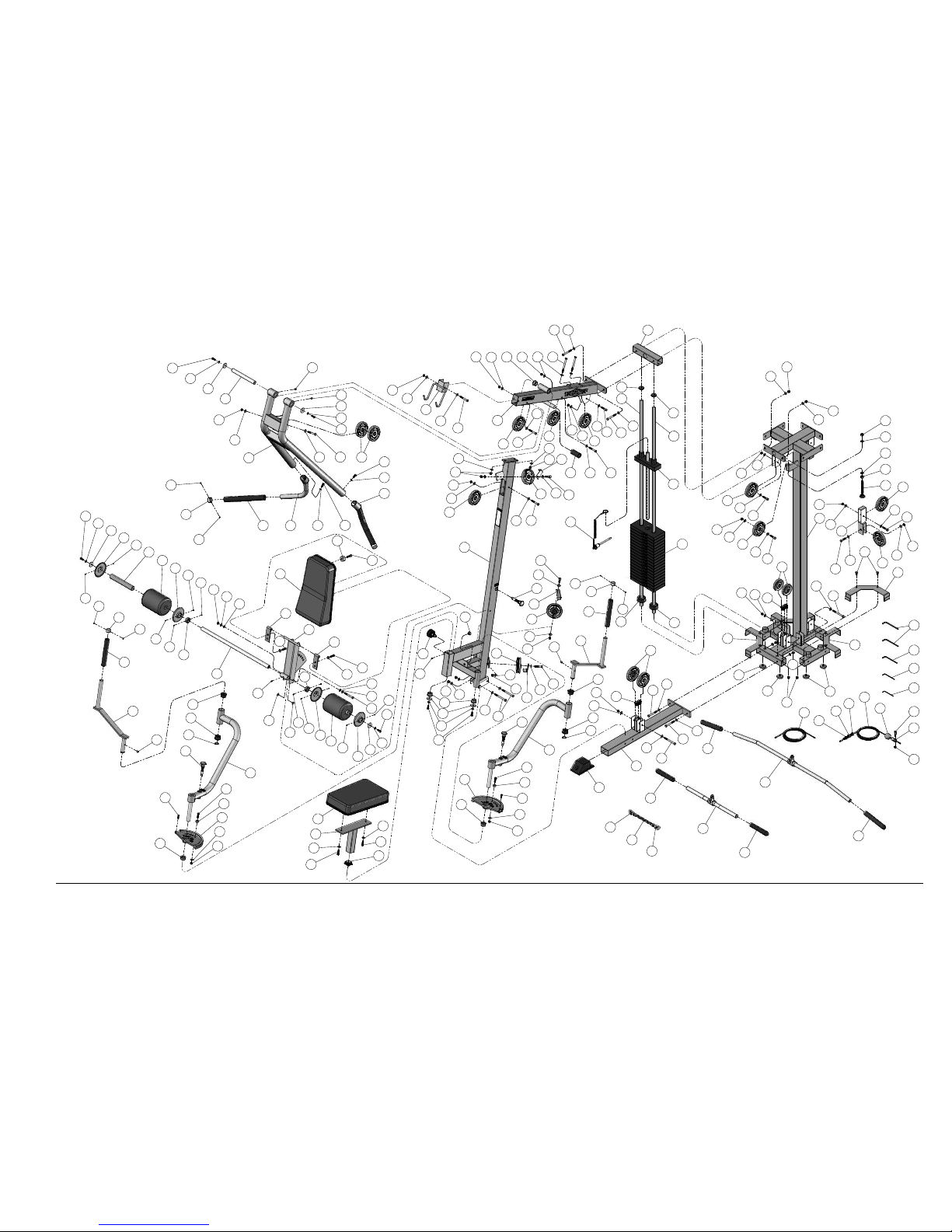
Apollo Modular Gym System (Base Unit) Fold-Out Page 20PARTS LIST
REV1
ITEM NO. DESCRIPTION PART NO. QTY. QTY. ITEM NO. DESCRIPTION PART NO. QTY. QTY. ITEM NO. DESCRIPTION PART NO. QTY. QTY.
1 ACTUATOR ARM UP0344 1
59 ABS PIPE 2 X 19 3/8 BNH1639 2 115 NYLON BUSHING 1 X 1 1/2 X 7/8 X 1 3/4 X 1/8 BNH0531 4
2 BACK PAD ADJUSTABLE BRACKET UP0554 1
60 ALUMINUM CAM PLATE 3/4 X 5" RADIUS BNH1153 2 116 NYLON FLAT WASHER 1 X 1 1/4 X 1/16 BNH0393 2
3 BACK PAD ADJUSTABLE TUBE UP0347 1
61 ALUMINUM CAP 1.020" RD (CAP-100) BNH0537 4 117 NYLON FLAT WASHER 3/8 ID X 3/4 OD X 1/16 THK BNH0248 4
4 BENCH PRESS ADJUSTABLE SEAT FRAME UP0676 1
62 ALUMINUM CAP 1.270" RD (CAP -125) BNH0538 4 118 NYLON INSERT JAM LOCK NUT B/O 3/8-16 BNH0365 18
5 BENCH PRESS BACK PAD UP0370 1
63 ALUMINUM COLLAR 1.0312 ID X 1.521 OD X .500 THK. BNH1519 2 119 NYLON INSERT LOCK NUT B/O 3/8-16 BNH0214 46
6 BENCH PRESS SEAT PAD UP0372 1
64 ALUMINUM FOOT ROLL HOLDER 1 5/16 ID X 4 1/2 OD X 3/4 BNH1509 4 120 NYLON INSERT LOCK NUT B/O 5/16-18 BNH0215 2
7 BOTTOM CONNECTOR PRESS BAR/PEC FLY UP2006 1
65 ALUMINUM FOOT ROLL HOLDER 2 3/8 ID X 4 1/2 OD X 3/4 BNH1510 4 121 NYLON SPACER 3/8 X 3/4 X 3/8 BNH0392 2
8 CABLE RETAINER BRACKET UP0014 4
66 ALUMINUM PULLEY 3/8" X 3 1/2" BNH1266 2 122 PLASTIC END CAP 2 X 3 BNH0606 4
9 CHROME PEC DEC SWIVEL HANDLE UP0324 2
67 ALUMINUM PULLEY 3/8" X 4 1/2" BNH0069 19 123 PLASTIC INSERT CAP 1 3/4" SQ BNH0053 2
10 CHROME SOLID GUIDE ROD 3/4 X 72 UP0124 8
68 ALUMINUM WASHER 3/8 X 2.584 OD X .15 THK. BNH1521 2 124 PLASTIC INSERT CAP 1" X 2" BNH0005 4
11 CIRCULAR PLATE W/AXLE UP0671 1
69 BALL BEARING #W 516 BNH0628 2 125 PLASTIC INSERT CAP 2 X 3 BNH0052 1
12 CLOSED-END DOUBLE PULLEY BRACKET UP0329 1
70 BRONZE BUSHING 1 X 1 1/4 X 3/4 X 1 1/2 X 1/8 BNH0527 12 126 PLASTIC INSERT CAP 2" SQ BNH0012 9
13 FOAM ROLL 1 X 5 1/2 X 7 1/4 UP0350 2
71 BUTTON HEAD SOCKET CAP SCREW B/O 3/8-16 X 1 BNH0115 8 127 PLASTIC TIES 14 1/2" BNH0703 2
14 FOAM ROLL 2 X 5 1/2 X 18 UP2031 2
72 BUTTON HEAD SOCKET CAP SCREW B/O 3/8-16 X 1 1/4 BNH0896 2 128 PLASTIC TUBE GUIDE W/LIP-TEETH 2 1/4" SQ BNH0059 2
15 FOOT ROLL TUBE 1 X 29 UP0974 1
73 CHROME CAP 2" RD BNH1137 2 129 PULL PIN 1/2 X 2 7/8 (YELLOW KNOB) BNH0641 1
16 FRONT UPRIGHT UP2008 1
74 CHROME WASHER 3/8 X 1 1/2 BNH1015 6 130 PULL PIN 1/2 X 3 1/2 (YELLOW KNOB) BNH0603 4
17 GUIDE ROD RETAINER UP2033 3
75 CLEVIS BRACKET 3/16" BNH0076 1 131 PULL PIN 1/4 X 3 1/2 (YELLOW KNOB) BNH0713 1
18 GUIDE ROD RETAINER PRESS BAR STATION UP2010 1
76 COIL CHAIN Z/P 3/16 X 8 BNH1214 1 132 PVC 1 X 8 3/4 BNH1611 2
19 HANDLE LEFT SIDE UP0271 1
77 DECAL-1" RD SILVER MYLAR CIRCLE BNH0015 4 133 RETAINING SNAP RING EXT .925 X 1 X .042 BNH0419 2
20 HANDLE RIGHT SIDE UP0270 1
78 DECAL-ADJUST CABLE HERE BNH0789 2 134 ROLL PIN Z/P 3/8 X 1 1/2 BNH0483 1
21 LAT BAR HOLDER 2 X 3 UP0327 1
79 DECAL-CAUTION 1 3/4 X 5 1/2 BNH0126 1 135 RUBBER BUMPER 3/8 X 1 1/2 BNH0514 1
22 LAT CABLE UP2021 1
80 DECAL-CAUTION LAT BAR HOLDER 5 X 1 BNH0140 1 136 RUBBER DONUT 3/4 X 2 1/2 BNH0068 8
23 LEG EXTENSION ARM SUPPORT UP2028 1
81 DECAL-DANGER TIGHTEN THIS RET..., 3/4 X 1 1/2 BNH0142 6 137 RUBBER GRIP 1 ID X .125 X 8 BNH0966 2
24 LEG EXTENSION BACK PAD UP0371 1
82 DECAL-EXERCISE LAT, VERTICAL PRESS, PEC FLY & LEG EXT BNH1673 1 138 RUBBER GRIP 1 ID X .125 X 8 1/2 BNH1075 2
25 LEG EXTENSION BOTTOM CONNECTOR UP2001 1
83 DECAL-EXR LAT, MID ROW, PEC FLY, LEG EXT & MULTI-PRESS BNH1674 * 1 139 RUBBER GRIP 1 X 6 1/4 BNH0296 4
26 LEG EXTENSION CABLE UP2025 1
84 DECAL-FOR BEST PERFORMANCE 1 1/4 X 1 1/2 BNH0143 4 140 RUBBER GRIP 1.1875 ID X .125 X 13 BNH0853 * 2
27 LEG EXTENSION FRONT FRAME UP0666 1
85 DECAL-WEIGHT NUMBERS REF TP-10 (200 lbs) BNH1542 4 141 RUBBER GRIP 1.1875 ID X .125 X 4 5/8 BNH1643 6
28 LEG EXTENSION SEAT FRAME UP2002 1
86 DECAL-WARNING KEEP HANDS AND FINGERS... BNH0620 1 142 RUBBER GROMMET 3/4" ID BNH0401 8
29 LEG EXTENSION SEAT PAD UP0348 1
87 EDGE PROTECTOR CHROME 18 GA X 72 BNH1836 8 143 RUBBER STOPPER 1 ID X .187 X 3 BNH0976 2
30 LONG ADJUSTABLE STOPPER UP0331 1
88 FINISHED HEX NUT B/O 1/2-13 BNH0201 4 144 SHOULDER BOLT ALLOY 3/8 X 3/4 BNH0718 2
31 MAGNETIC SELECTOR PIN W/COIL 3/8 X 4 UP3035 4
89 FLAT PHILLIPS MACHINE SCREW 8-32 X 1/4 BNH0408 2 145 SNAP LINK Z/P 8MM X 80MM BNH0065 3
32 MID ROW HANDLE LT SIDE UP4236 * 1
90 FLAT PHILLIPS SCREW ZINC # 2 X 1/2 BNH1480 2 146 SOCKET HEAD CAP SCREW B/O 1/4-20 X 3/4 BNH0452 2
33 MID ROW HANDLE RT SIDE UP4237 * 1
91 FLAT PHILLIPS SCREW ZINC # 5 X 1/2 BNH1481 4 147 SOCKET SET SCREW ALLOY 1/4-20 X 1/4 BNH0790 1
34 MID ROW PULL ARM UP4221 * 1
92 FLAT WASHER B/O 3/4 X 2" BNH0878 8 148 SOCKET SET SCREW ALLOY 10-32 X 1/4 BNH0473 4
35 PEC DEC ARM LEFT SIDE UP0819 1
93 FLAT WASHER SAE B/O 3/8" BNH0239 101 149 SOCKET SET SCREW ALLOY 10-32 X 1/8 BNH0473 24
36 PEC DEC ARM RIGHT SIDE UP0818 1
94 HEX HEAD CAP SCREW GR-5 B/O 3/8-16 X 1 BNH0275 2 150 SOCKET SET SCREW ALLOY 3/8-16 X 1/2 BNH0474 6
37 PEC DEC CABLE UP2022 1
95 HEX HEAD CAP SCREW GR-5 B/O 3/8-16 X 1 1/2 BNH0303 1 151 SPLIT HEX TAP BOLT GR-5 B/O 1/2-13 X 3 1/2 BNH1131 2
38 PIVOT ARM LEG EXTENSION UP2030 1
96 HEX HEAD CAP SCREW GR-5 B/O 3/8-16 X 1 1/4 BNH0273 10 152 SPLIT LOCK WASHER B/O 3/8" BNH0658 10
39 PIVOT AXLE 1 X 8 1/8 UP0152 2
97 HEX HEAD CAP SCREW GR-5 B/O 3/8-16 X 1 3/4 BNH0274 8 153 SPLIT LOCK WASHER Z/P 1/2" BNH0572 4
40 PIVOT AXLE 1 X 9 UP4238 * 1
98 HEX HEAD CAP SCREW GR-5 B/O 3/8-16 X 2 BNH0279 3 154 TUFFSTUFF LOGO ALUMINUM LARGE BNH1324 2
41 PRESS BAR SELECTOR HOUSING UP0326 1
99 HEX HEAD CAP SCREW GR-5 B/O 3/8-16 X 2 1/2 BNH0276 3 155 TUFFSTUFF LOGO ALUMINUM SMALL BNH1323 2
42 PRESS BAR (DETACHABLE HANDLES) UP3573 1
100 HEX HEAD CAP SCREW GR-5 B/O 3/8-16 X 2 3/4 BNH0278 2 156 TURN/PULL PIN W/KNOB AND LOCK BNH0989 2
43 REINFORCEMENT PLATE 1/4 X 2 X 8 1/2 UP2106 3
101 HEX HEAD CAP SCREW GR-5 B/O 3/8-16 X 3 1/4 BNH0312 17 157 URETHANE BUMPER 1 3/4 BNH0229 8
44 REMOVABLE HANDLE LT SIDE UP3574 1
102 HEX HEAD CAP SCREW GR-5 B/O 3/8-16 X 3/4 BNH0283 16 158 URETHANE BUMPER 962 BNH0244 2
45 REMOVABLE HANDLE RT SIDE UP3575 1
103 HEX HEAD CAP SCREW GR-5 B/O 3/8-16 X 4 BNH0285 2
46 SAFETY SHIELD COVER PLATE 1 1/2 X 5 UP1767 1
104 HEX HEAD CAP SCREW GR-5 B/O 3/8-16 X 4 1/4 BNH0317 11
* Mid Row Station Item Quantities
47 SWIVEL FOAM ROLL TUBE UP2026 1
105 HEX KEY 3/32" BNH0372 1
48 TOP ADJUSTABLE LEG HOLDER TUBE UP0672 1
106 HEX KEY ALLOY 1/8" BNH0767 1
49 TOP PULLEY ASSEMBLY UP2007 1
107 HEX KEY ALLOY 3/16" BNH0371 1
50 WEIGHT SHIELD UP2017 3
108 HEX KEY ALLOY 7/32" BNH0575 2
51 WEIGHT SHIELD (APT-5.1) UP1750 1
109 LABEL-ADJUSTMENT BACK PAD 9/16 X 7.5 BNH0080 1
52 WEIGHT SHIELD HOLDER UP2016 8
110 LABEL-ADJUSTMENT PRESS BAR 9/16 X 6 BNH0079 1
53 WEIGHT STACK FRAME UP2000 1
111 LAT BAR 48" BNH0295 1
ITEM NO. DESCRIPTION PART NO. QTY. QTY.
54 WEIGHT STACK SPACER 4" UP0786 2
112 LOW ROW BAR 20" BNH0294 1
66 NYLON PULLEY 3/8 X 3 1/2 BNH0553 2
56 10 LB STEEL WEIGHT PLATE BLACK 4 9/16 X 9 7/16 BNH1650 76 113 METAL HINGE BNH0046 2
67 NYLON PULLEY 3/8 X 4 1/2 BNH0506 19
58 10 LB TOP PLATE W/ADJ SLTR BAR 19 BLK WTS BNH1982 4 114 NYLON BALL 1 3/4 X 5/16 BNH0047 1
All parts same as Deluxe, except for the parts listed below
Parts List (Base Unit)
Apollo Modular Gym Systems (Standard)
Apollo Modular Gym Systems (Deluxe)
Parts List (Base Unit)
CHART
BOLD FONT = SUB-ASSEMBLY PARTS
REGULAR FONT = HARDWARE
Page 26

Apollo Modular Gym System (Base Unit)Fold-Out Page 21
A1
A2
A7
A8
A9
A10
A4
A3A5
B3B5
B4
B1
166
85
118
126
167
115
FIG. A
111
145
120
114
75
144
27
72
176
90
172
24
FIG. B
168
25
119
A1
A2
A4
A3
A6
A5
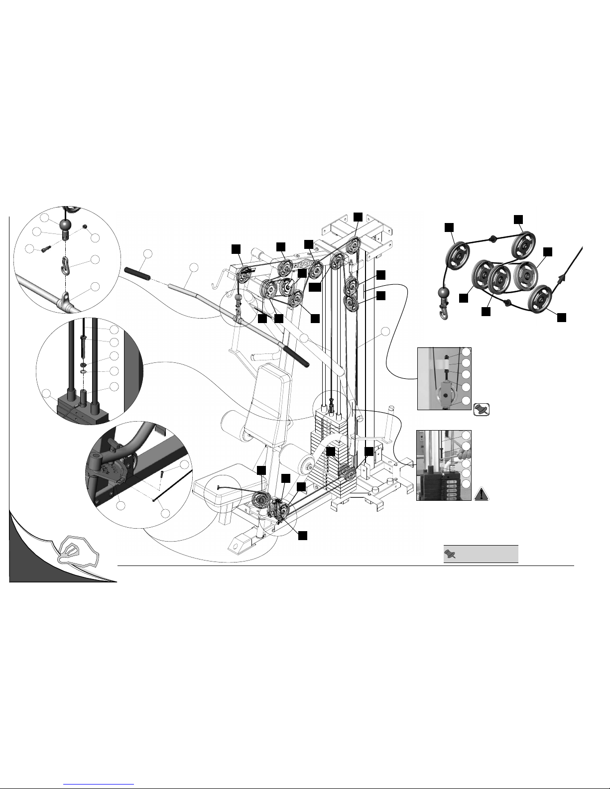
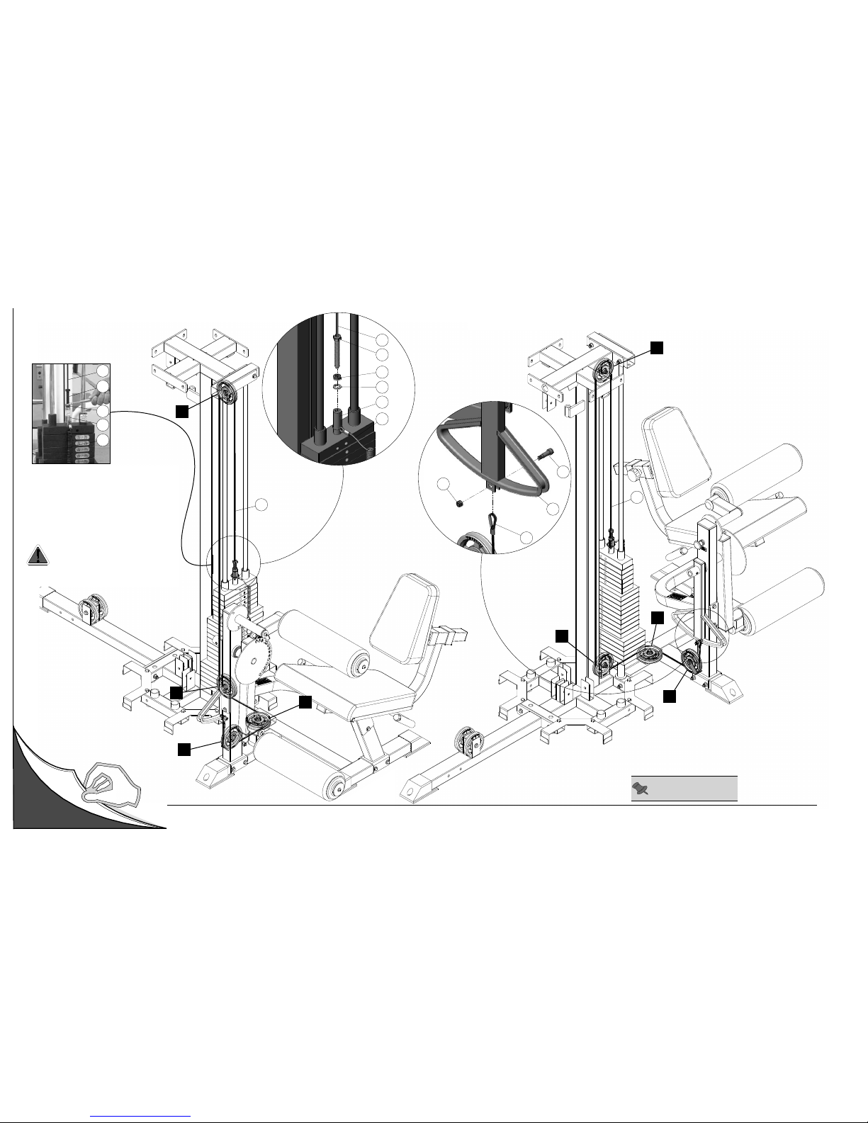
Cable Mapping Diagram Vertical Multi-Press Station
Adjustable Stopper (#30)
1. Loosen both Finished Hex Nuts 1/2-13
(#88).
2. Twist the Adjustable Stopper (#30) to
left or right until it makes contact with the
Closed-End Double Pulley Bracket (#12).
3. Re-tighten the Finished Hex Nuts 1/2-13
(#88) to complete the cable adjustment.
88
12
30
53
88
22
31
58
151
88
Cable Adjustment
1. Loosen the Finished Hex Nut 1/2-13 (#88).
2. Thread the Cable Hex Tap Bolt (#151) in
or out of the threaded socket of the Selector
Bar (#58) to give the Cables proper tension.
3. Re-tighten the Finished Hex Nut 1/2-13
(#88) to complete the adjustment.
Note: Be sure that the Closed-End
Double Pulley Bracket (#12)
is resting
on the Adjustable Stopper (#30).
Caution: Make sure the Cable Hex
Tap Bolt (#151) is threaded at least
1/2” into the threaded socket of the
Selector Bar (#58) once the cable
adjustment has been completed.
Unfold
Page
Note: Some parts have
been cut away for clarity.
FIG. C
22
151
88
153
58
31
146
37
60
139
111
24
25
A6
B2
B6
B7
Page 27

39
811
06
121
27
6
41
07
0
31
331
511
51
1
63
051
9
83
1
94
1
16
9
41
94
1
17
251
47
46
9
41
231
31
941
941
26
46
9
41
841
81
1
39
711
36
8
41
9
41
51
741
711
71
1
841
9
41
36
46
31
941
46
47
17
251
9
41
101
3
9
711
39
69
31
1
311
69
5
59
621
49
2
51
14
1
141
14
1
44
54
941
26
94
1
24
07
07
93
77
39
8
11
03
1
93
77
6
21
05
1
7
6
77
051
0
01
39
051
14
77
621
001
39
12
39
811
39
94
39
811
07
811
39 401
101 39
241
24
1
81
39
101
8
11
76
39
79
39
39 99
76
39
911
8
3
41
39
89
39
99
76
39
911
811
39
76
61
13
03
1
89
39
8
39
911
051
9
8
31
631
941
16
941
631
55
65
75
01
01
85
511
511
331
53
0
31
27
121
6
41
06
0
7
39
81
1
221
811
39
421
76
39
1
01
39
101
39
301
931
7
931
67
541
541
211
931
111
931
22
351
88
151
411
441
57
021
50
1
6
01
701
801
751
911
751
751
911
811
39
421
66
39
301
201
25
76
3
9
79
39
03
21
39
79
39
811
73
79
39
76
39
811
79
39
76
39
811
76
88
351
351
88
89
39
8
76
39
39
401
911
07
47
17
911
98
6
51
851
39
69
321
69
39
4
6
39
911
39
911
76
251
39
2
99
7
6
531
811
35
25
25
Apollo Modular Gym System (Base Unit) Fold-Out Page 22Exploded View Diagram Vertical Multi-Press Station
56
Page 28
Apollo Modular Gym System (Base Unit)Fold-Out Page 23
A1
A2
A7
A8
A9
A10
A4
A3A5
B3B5
B4
B1
166
85
118
126
167
115
FIG. A
111
145
120
114
75
144
27
72
176
90
172
24
FIG. B
168
25
119
A1
A2
A4
A3
A6
A5
Cable Mapping Diagram Mid Row Station
Adjustable Stopper (#30)
1. Loosen both Finished Hex Nuts 1/2-13
(#88).
2. Twist the
Adjustable Stopper (#30) to
left or right until it makes contact with the
Closed-End Double Pulley Bracket (#12).
3. Re-tighten the Finished Hex Nuts 1/2-13
(#88) to complete the cable adjustment.
88
12
30
53
88
22
31
58
151
88
Cable Adjustment
1. Loosen the Finished Hex Nut 1/2-13 (#88).
2. Thread the Cable Hex Tap Bolt (#151) in
or out of the threaded socket of the Selector
Bar (#58) to give the Cables proper tension.
3. Re-tighten the Finished Hex Nut 1/2-13
(#88) to complete the adjustment.
Note: Be sure that the
Closed-End
Double Pulley Bracket (#12) is resting
on the Adjustable Stopper (#30).
Caution: Make sure the Cable Hex
Tap Bolt (#151) is threaded at least
1/2” into the threaded socket of the
Selector Bar (#58) once the cable
adjustment has been completed.
Unfold
Page
Note: Some parts have
been cut away for clarity.
FIG. C
22
151
88
153
58
31
146
37
60
139
111
24
25
A6
B2
B6
B7
Page 29
39
81
1
06
1
21
27
6
4
1
07
0
3
1
331
5
11
5
1
1
63
051
9
831
941
16
94
1
941
17
251
47
46
941
231
31
46
9
41
841
8
11
39
711
36
84
1
941
51
741
711
711
84
1
9
41
36
46
31
94
1
46
47
1
7
251
9
41
10
1
39
711
39
69
311
3
11
69
5
59
001
39
12
39
81
1
39
94
39
8
11
07
811
39 401
101 39
241
241
81
39
101
811
76
39
79
39
39 99
76
39
911
8
341
39
89
39
99
76
39
911
8
11
39
76
61
13
031
89
39
8
39
911
051
9
831
6
31
941
16
941
631
55
65
75
01
01
85
511
511
331
53
03
1
27
121
641
06
07
39
811
221
811
39
421
76
39
101
39
101
39
301
931
7
931
67
541
541
211
931
111
931
22
35
1
88
151
411
441
57
021
501
601
701
801
751
911
751
751
911
811
39
421
66
39
301
201
25
76
39
79
39
03
21
39
79
39
811
73
79
39
76
39
811
79
39
76
39
811
76
88
351
351
88
8
9
39
8
76
39
39
40
1
9
11
07
47
17
911
98
651
8
51
39
69
321
69
39
4
6
39
911
39
911
76
251
39
2
99
76
53
1
8
11
35
25
25
23
17
251
17 251
33
0
41
9
41
26
9
41
43
39
00
1
76
39
81
1
04
47
25
1
17
05
1
17
251
4
7
05
1
Apollo Modular Gym System (Base Unit) Fold-Out Page 24Exploded View Diagram Mid Row Station
56
Page 30
Apollo Modular Gym System (Base Unit)Fold-Out Page 25
27
72
90
172
44
176
FIG. B
Cable Mapping Diagram Leg Developer Station
FIG. A
26
144
1
120
26
151
88
153
58
31
C1
C2
C3
C4
C4
C3
C2
C1
26
26
Left Side View Right Side View
26
31
58
151
88
Cable Adjustment
1. Loosen the Finished Hex Nut 1/2-13 (#88).
2. Thread the Cable Hex Tap Bolt (#151) in
or out of the threaded socket of the Selector
Bar (#58) to give the Cable proper tension.
3. Re-tighten the Finished Hex Nut 1/2-13 (#88)
to complete the adjustment.
Caution: Make sure the Cable Hex Tap
Bolt (#151) is threaded at least 1/2” into
the threaded socket of the Selector Bar
(#58) once the cable adjustment has
been completed.
Unfold
Page
Note: Some parts have
been cut away for clarity.
Page 31

Apollo Modular Gym System (Base Unit) Fold-Out Page 26Exploded View Diagram Leg Developer Station
71
34
3
9
101
39
241
0
1
01
241
85
79
76
811
39
39
911
39
911
35
76
39
79
39
811
7
39
911
29
29
45
29
631
45
29
631
55
65
75
39
40
1
96
13
1
431
421
5
21
131
76
8
39
401
401
911
39
9
11
39
401
39
72
621
921
39
911
911
421
39
39
911
941
911
39
941
32
611
83
07
11
07
37
47
251
17
941
941
76
621
79
39
39
101
221
221
221
52
151
88
351
62
441
021
9
41
86
17
941
41
95
251
56
811
39
10
1
39
25
25
25
25
39
401
101
941
16
941
731
39
101
1
01
39
91
39
82
69
69
39
911
911
69
39
91
1
39
621
39
911
821
651
98
821
02
17
251
86
16
731
941
92
07
84
07
47
251
17
37
941
56
941
95
41
56
941
42
3
39
69
39
69
321
74
56
39
96
56
Page 32

Apollo Modular Gym System (Base Unit)Fold-Out Page 27
88
97
58
88
57
193
88
97
58
88
57
88
97
58
88
57
88
97
58
88
57
125
125
17
18
125
125
17
17
125
125
18
17
125
125
17
52
52
52
52
52
Unfold
Page
119
119
87
102
50
52
87
82
87
102
52
50
87
119
119
119
119
51
87
52
102
87
87
52
50
87
102
87
 Loading...