

Page 1
AMERICA’S PREMIER EXERCISE EQUIPMENT
OWNER’S MANUAL
MULTI PRESS STATION
AP-71MP Rev0
Revision Date 9-17-09
Page 2
Introduction
About the MULTI PRESS STATION
Congratulations on your new purchase of the MULTI PRESS
STATION. We hope you are completely satisfi ed with this product
and wish you many years of enjoyment.
Tuff Stuff Equipment
This Tuffstuff product has been built to precise quality standards
and has been carefully packaged to ensure that damage will not
occur during shipment. The Home Lifetime Warranty and signature
indicating fi nal inspection has been conducted by our line foreman,
is an expression of our confi dence in the completeness, the
materials, and workmanship of this product.
Warranty
SEE A COPY OF WARRANTY ON BACK PAGE.
Registration Card
To avoid unnecessary delays in warranty service and to insure that
a permanent record of your purchase is on fi le with our factory,
be sure to complete the warranty registration card and send it to
TuffStuff Fitness Equipment today.
Specifi cations
1. Maximum Wt. Capacity - 200 lbs.
2. Total Machine Weight - 483 lbs.
3. Footprint (LWH) - Height is 84”. For footprints refer to
the Center Post/Rear Post Assembly
Manuals.
Prior to the Assembly of the MULTI PRESS STATION
1. We advise you to consult your local Tuff Stuff retailer if you should
have a question or problem regarding the proper assembly of
this unit.
Tool Requirements
1. One 7/8” combination wrench
2. Two 3/4” combination wrench
3. One 9/16” combination wrench
4. One 1/2” combination wrench
5. One 7/16” combination wrench
6. One adjustable wrench
7. One ratchet
8. One 3/4” socket
9. One 9/16” socket
10. One rubber mallet
11. Windex or household glass cleaner
12. Measuring tape
13. Utility knife
14. The hex key alloy set included in the Center Post/Rear Post
box.
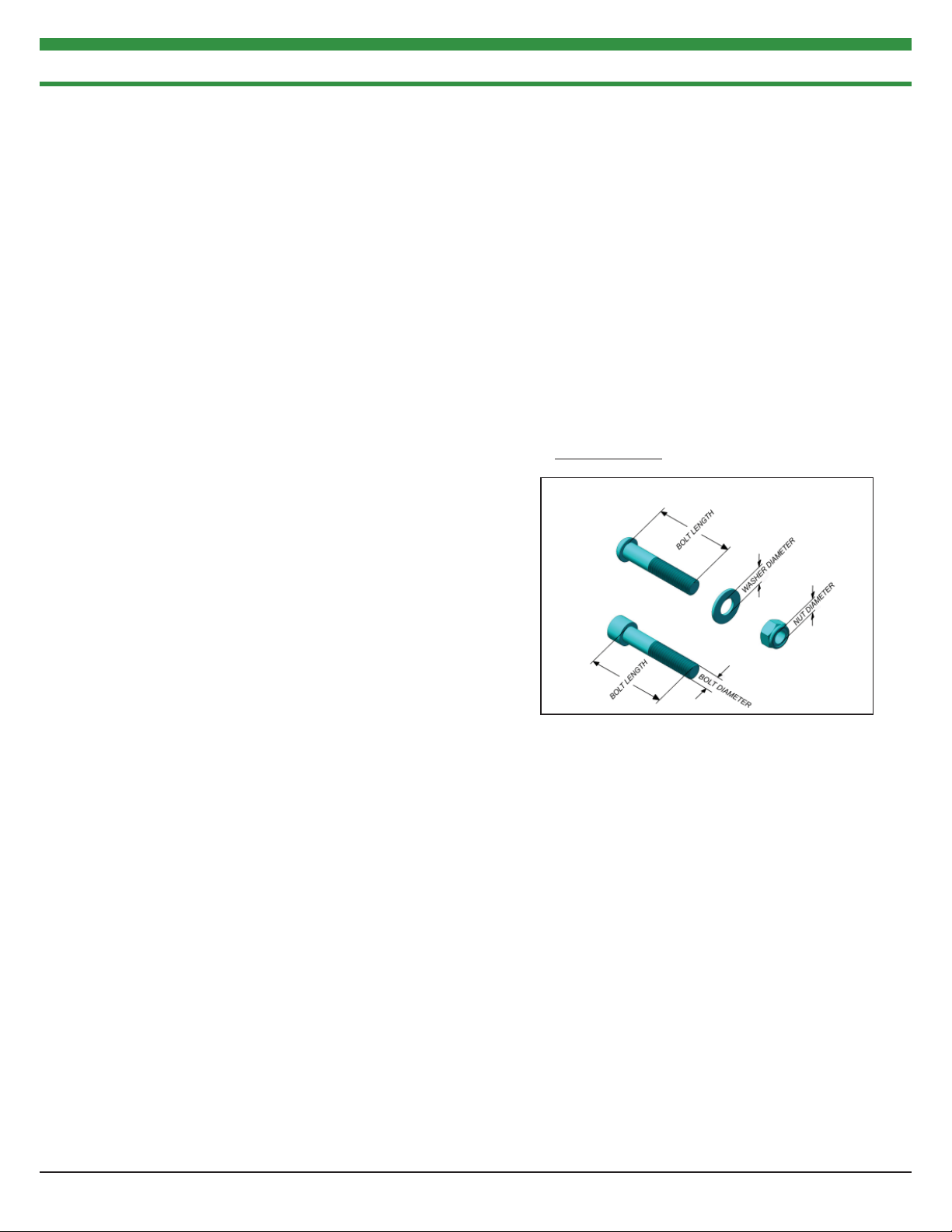
Hardware Measurement Diagram
Note: Due to continuing product improvements, specifi cations and designs are subject to change
without notice.
Safety Precautions
Safety First
Regardless of how enthusiastic you may be about getting on
your equipment and exercising, take the time to ensure that your
safety is not jeopardized. A moment’s lack of attention can result
in an accident, as can failure to observe certain simple safety
precautions.
1. Read, study and understand the Assembly Instructions and all the
warning labels on this product. Furthermore, it is recommended
to familiarize yourself and others with the proper operation and
workout recommendations for this Tuff Stuff product prior to
use.
2. It is imperative that you retain this Assembly Instructions and
be sure all warning labels are legible and intact. Replacement
Assembly Instructions and labels are available from your local
Tuff Stuff retailer.
4. Frayed or worn cables can be dangerous and may cause injury.
Periodically check the cable for any indication of wear.
5. Use proper discretion when children are present.
6. Keep hands, limbs, loose clothing and long hair well out of the
way of moving parts.
7. Do not attempt to lift more weight than you can control safely.
8. Inspect the Unit for any sign of wear on parts, hardware becoming
loose or cracks on welds. If a problem is found do not use or
allow the machine to be used until the defective part is repaired
or replaced.
3. Consult with your physician before beginning any exercise
program.
2 AP-7000 SERIES MULTI PRESS STATION
Page 3

INDEX
IMPORTANT ASSEMBLY INSTRUCTION NOTE..................4
FIRST STEPS FOR A SINGLE STATION...................................5
MULTIPLE STATION ASSEMBLY STEPS.................................7
LAT CABLE..................................................................................12
TENSION CABLE........................................................................14
ABDOMINAL CABLE................................................................15
EXPLODED VIEW.......................................................................19
PARTS LIST...................................................................................20
MAINTENANCE.........................................................................21
3AP-7000 SERIES MULTI PRESS STATION
Page 4

IMPORTANT ASSEMBLY INSTRUCTION NOTE
INSTRUCTIONS FOR A SINGLE STATION ASSEMBLY ONLY:
FOR STEPS 1 AND 2 YOU WILL NEED SOME HARDWARE THAT IS
PROVIDED IN THE AP-70RP BOX. ONCE YOU COMPLETE STEPS
1 AND 2 SKIP TO STEP 5 TO RESUME INSTALLATION.
INSTRUCTIONS FOR A MULTI STATION ASSEMBLY ONLY:
BEGIN ASSEMBLY IN STEP 3. FOR STEPS 3 AND 4 YOU WILL
NEED SOME HARWARE THAT IS PROVIDED IN THE AP-70CP
BOX.
4 AP-7000 SERIES MULTI PRESS STATION
Page 5
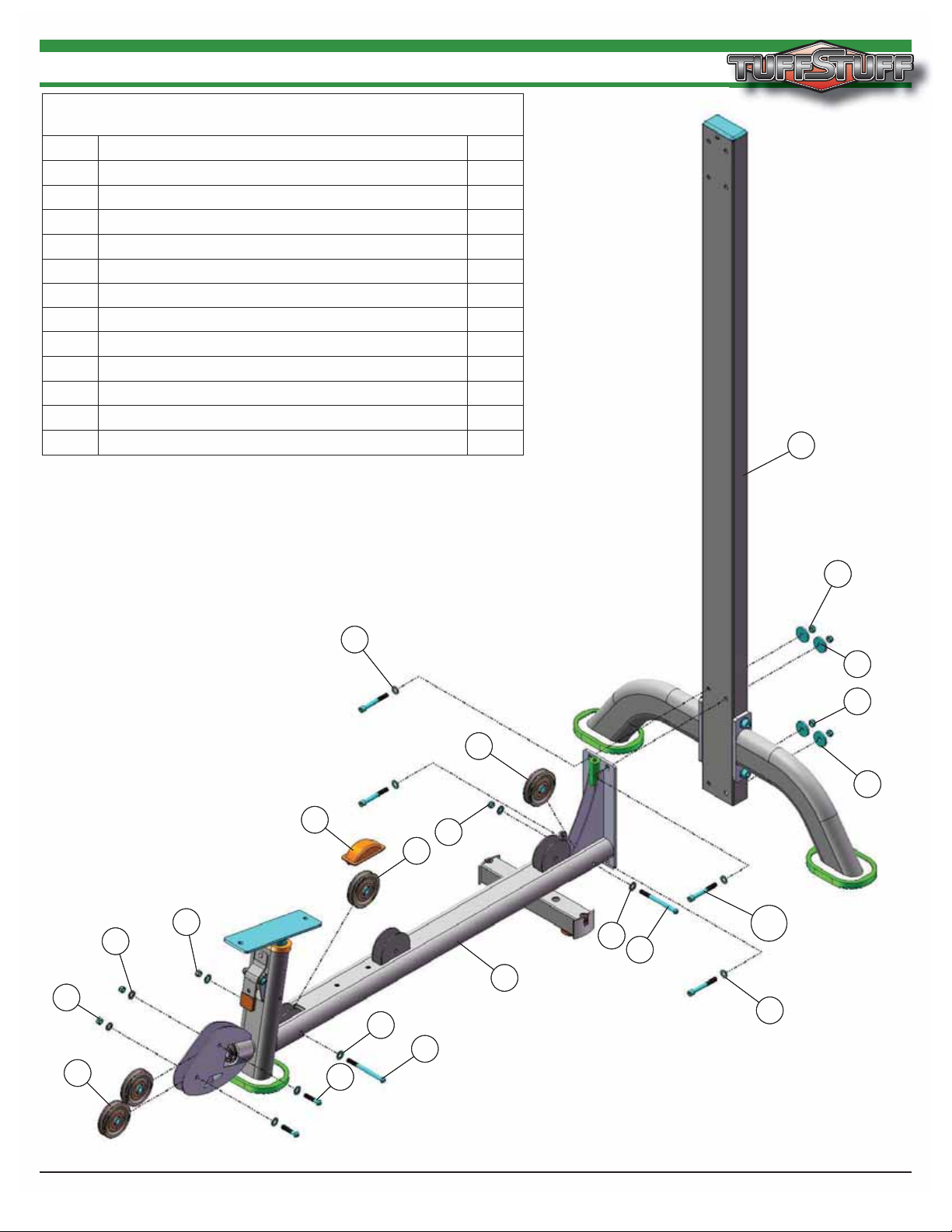
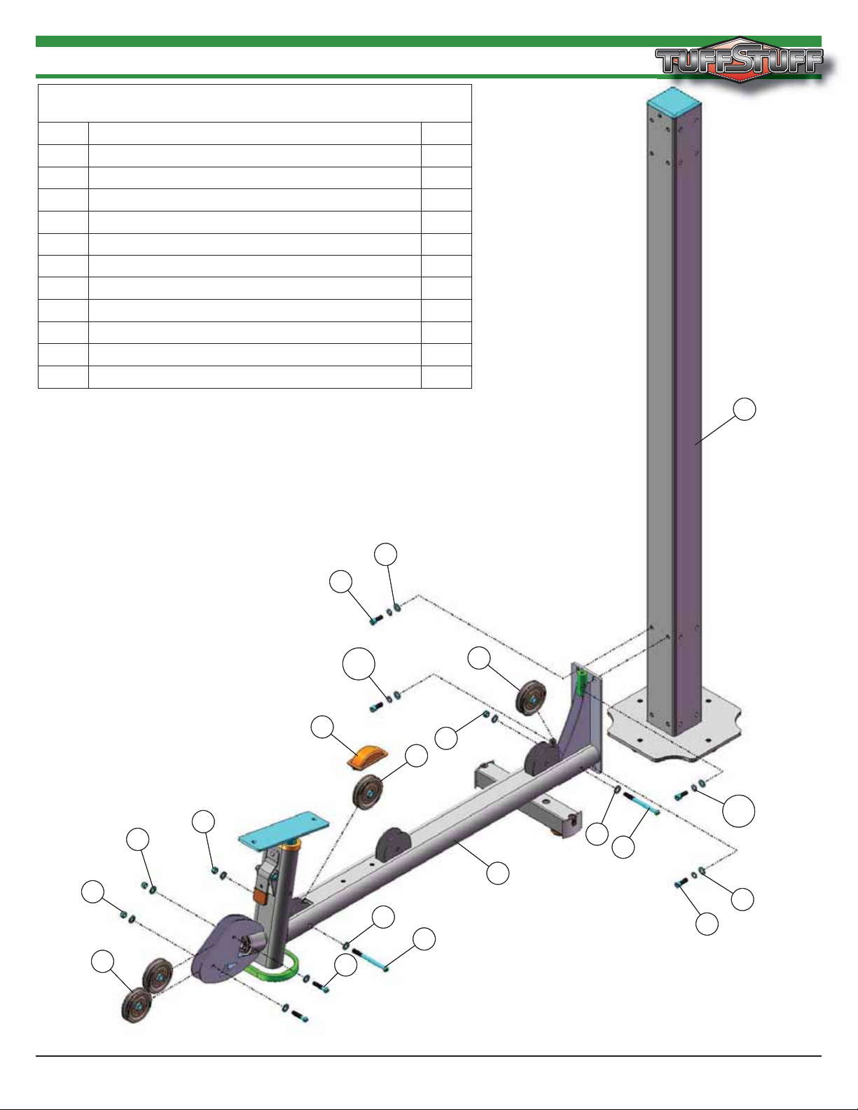
STEP 1
Assembly List
Item # Description Qty.
B1 REAR POST 1
B7 FLAT WASHER SAE N/P 3/8” 4
B8 FLAT WASHER N/P 3/8 ID X 1 1/2 OD X 3/16 4
B9 NYLON INSERT LOCK NUT N/P 3/8-16 4
B11 SOCKET CAP SCREW GR-8 N/P 3/8-16 X 3 4
6 BASE FRAME 1
38 BLACK NYLON PULLEY 3/8 X 1 X 3 1/2 4
46 BUTTON HEAD SCREW GR-8 N/P 3/8-16 X 1 3/4 2
50 BUTTON HEAD SCREW GR-8 N/P 3/8-16 X 4 1/2 2
66 FLAT WASHER SAE N/P 3/8” 8
77 NYLON INSERT LOCK NUT N/P 3/8-16 4
81 PLASTIC PULLEY COVER 1
B1
B1
77
77
38
38
66
66
77
77
81
81
46
46
B7
B7
66
66
38
38
50
50
77
77
38
38
B9
B9
B8
B8
B9
B9
B8
B8
B11
66
66
50
50
6
6
B11
B7
B7
AP-7000 SERIES MULTI PRESS STATION
5
Page 6
38
78
46
66
77
66
77
21
13
13
112
111
88
22
68
68
46
B9
B8
B7
B11
B7
B11
27
77
9
66
46
38
30
62
38
78
46
66
77
66
77
21
13
13
112
111
88
22
68
68
46
B9
B8
B7
B11
B7
B11
27
77
9
66
46
38
30
62
Assembly List
B7 FLAT WASHER SAE N/P 3/8” 4
Item # Description Qty.
B8 FLAT WASHER N/P 3/8 ID X 1 1/2 OD X 3/16 4
9999
9 FLOATING PULLEY BRACKET (3 1/2 PULLEY) 1
13 GUIDE RODS 2
21 SELECTOR PIN W/COIL 3/8 X 4 GOLD KNOB 1
22 SPACER 1 1/4 OD X 1 ID X 3 3/4 2
27 TOP GUIDE ROD HOUSING 1
30 GUIDE ROD 1/2 RD X 66 3/4 1
38 BLACK NYLON PULLEY 3/8 X 1 X 3 1/2 2
46 BUTTON HEAD SCREW GR-8 N/P 3/8-16 X 1 3/4 3
62 DECAL-WEIGHT NUMBERS REF TP-10 (200 lbs) 1
66 FLAT WASHER SAE N/P 3/8” 6
68 FLAT WASHER N/P 3/4 X 2 4
77 NYLON INSERT LOCK NUT N/P 3/8-16 3
78 NYLON PULLEY 3/8 X 1 X 4 1/2 BLACK 1
88 RUBBER DONUT 3/4 X 2 1/2 2
B9 NYLON INSERT LOCK NUT N/P 3/8-16 4
B11 SOCKET CAP SCREW GR-8 N/P 3/8-16 X 3 4
99 SOCKET SET SCREW N/P 10-32 X 1/8 1
111 10 LB STEEL WEIGHT PLATE BLACK 4 9/16 X 9 7/16 19
112 10 LB TOP PLATE W/ADJ SLTR BAR 19 BLK WTS 1
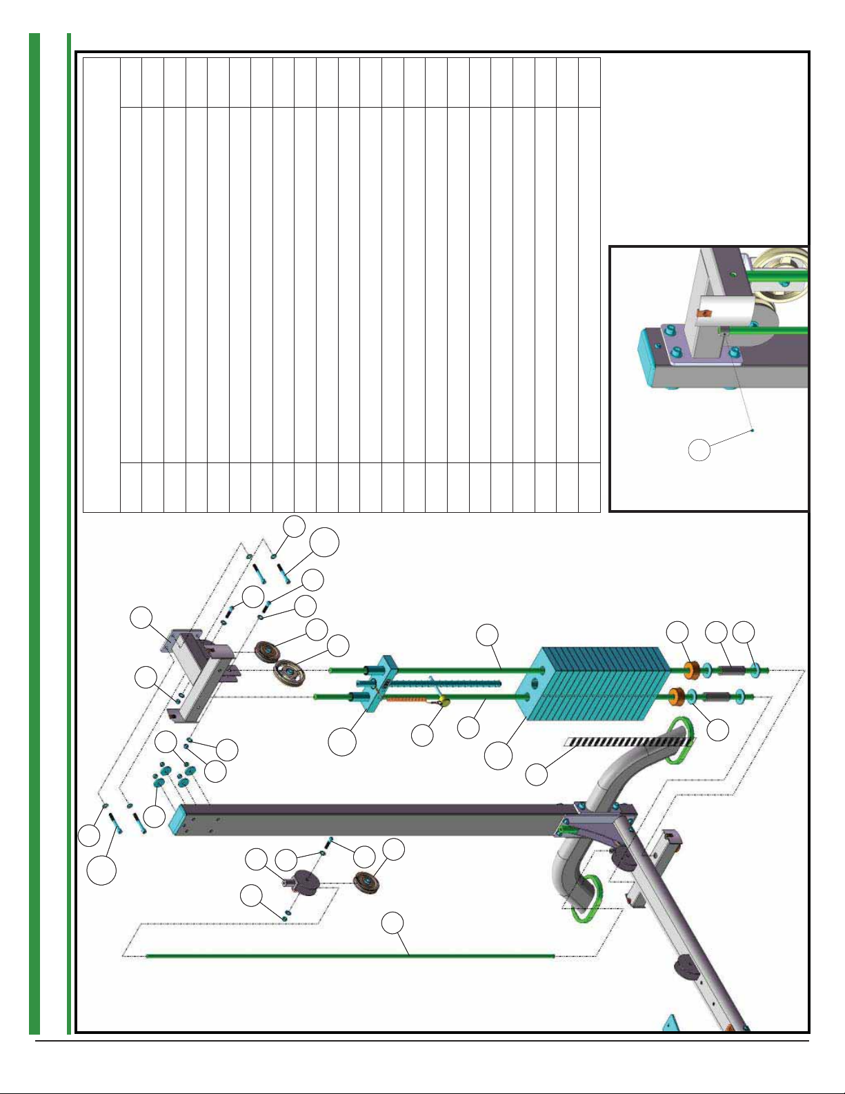
STEP 2
6 AP-7000 SERIES MULTI PRESS STATION
Page 7
STEP 3
Assembly List
Item # Description Qty.
A1 CENTER POST 1
A7 SOCKET CAP SCREW GR-8 N/P 3/8-16 X 1 4
A8 FLAT WASHER SAE N/P 3/8” 4
A10 SPLIT LOCK WASHER N/P 3/8” 4
6 BASE FRAME 1
38 BLACK NYLON PULLEY 3/8 X 1 X 3 1/2 4
46 BUTTON HEAD SCREW GR-8 N/P 3/8-16 X 1 3/4 2
50 BUTTON HEAD SCREW GR-8 N/P 3/8-16 X 4 1/2 2
66 FLAT WASHER SAE N/P 3/8” 8
77 NYLON INSERT LOCK NUT N/P 3/8-16 4
81 PLASTIC PULLEY COVER 1
A1
A1
77
77
38
38
66
66
77
77
81
81
A7
A7
46
46
A10
A10
A8
A8
66
66
38
38
50
50
77
77
38
38
A10
A10
66
66
50
50
6
6
A8
A8
A7
A7
AP-7000 SERIES MULTI PRESS STATION
7
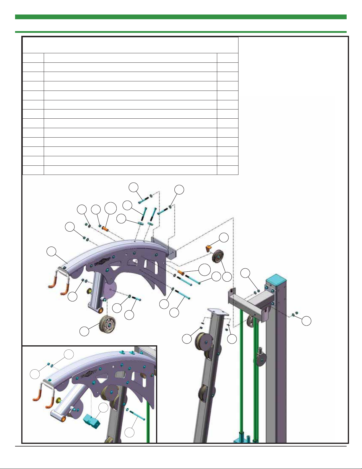
Page 8

A8
A10
A7
A7
A10
A8
38
78
46
66
77
66
77
21
13
13
112
111
88
22
68
68
46
27
77
9
66
46
38
30
62
A8
A10
A7
A7
A10
A8
38
78
46
66
77
66
77
21
13
13
112
111
88
22
68
68
46
27
77
9
66
46
38
30
62
Assembly List
A7 SOCKET CAP SCREW GR-8 N/P 3/8-16 X 1 4
A8 FLAT WASHER SAE N/P 3/8” 4
Item # Description Qty.
9 FLOATING PULLEY BRACKET (3 1/2 PULLEY) 1
13 GUIDE RODS 2
21 SELECTOR PIN W/COIL 3/8 X 4 GOLD KNOB 1
22 SPACER 1 1/4 OD X 1 ID X 3 3/4 2
27 TOP GUIDE ROD HOUSING 1
30 GUIDE ROD 1/2 RD X 66 3/4 1
38 BLACK NYLON PULLEY 3/8 X 1 X 3 1/2 2
46 BUTTON HEAD SCREW GR-8 N/P 3/8-16 X 1 3/4 3
62 DECAL-WEIGHT NUMBERS REF TP-10 (200 lbs) 1
66 FLAT WASHER SAE N/P 3/8” 6
68 FLAT WASHER N/P 3/4 X 2 4
77 NYLON INSERT LOCK NUT N/P 3/8-16 3
78 NYLON PULLEY 3/8 X 1 X 4 1/2 BLACK 1
88 RUBBER DONUT 3/4 X 2 1/2 2
99 SOCKET SET SCREW N/P 10-32 X 1/8 1
111 10 LB STEEL WEIGHT PLATE BLACK 4 9/16 X 9 7/16 19
A10 SPLIT LOCK WASHER N/P 3/8” 4
112 10 LB TOP PLATE W/ADJ SLTR BAR 19 BLK WTS 1
9999
STEP 4
8 AP-7000 SERIES MULTI PRESS STATION
Page 9

STEP 5
77
77
66
66
77
77
77
77
36
36
66
66
12
12
66
66
66
66
50
50
50
50
36
36
36
36
48
48
Assembly List
Item # Description Qty.
12 FRONT UPRIGHT 1
36 BLACK NYLON PULLEY 3/8 X 1 1/2 X 4 1/2 3
48 BUTTON HEAD SCREW GR-8 N/P 3/8-16 X 2 1/4 1
50 BUTTON HEAD SCREW GR-8 N/P 3/8-16 X 4 1/2 2
66 FLAT WASHER SAE N/P 3/8” 8
77 NYLON INSERT LOCK NUT N/P 3/8-16 3
96 SOCKET CAP SCREW GR-8 N/P 3/8-16 X 1 1/4 2
104 SPLIT LOCK WASHER N/P 3/8” 2
96
96
66
66
104
104
AP-7000 SERIES MULTI PRESS STATION
9
Page 10
STEP 6
Assembly List
Item # Description Qty.
25 TOP FRAME 1
29 CABLE RETAINER BRACKET 3 1/2 PULLEY 1
38 BLACK NYLON PULLEY 3/8 X 1 X 3 1/2 1
49 BUTTON HEAD SCREW GR-8 N/P 3/8-16 X 2 3/4 1
51 BUTTON HEAD SCREW GR-8 N/P 3/8-16 X 5 4
66 FLAT WASHER SAE N/P 3/8” 14
69 FLAT WASHER N/P 3/8 ID X 1 1/2 OD X 3/16 2
77 NYLON INSERT LOCK NUT N/P 3/8-16 9
78 NYLON PULLEY 3/8 X 1 X 4 1/2 BLACK 2
82 PLASTIC STOPPER 1
97 SOCKET CAP SCREW GR-8 N/P 3/8-16 X 3 4
114 FLANGED SPACER N/P 0.406 X 0.63 X 1.7186 (1.625) X 0.079 2
97
97
66
66
77
77
25
25
77
77
66
66
77
77
66
66
78
78
77
77
114
114
66
66
69
69
97
97
49
49
66
66
51
51
77
77
114
114
51
51
29
29
38
38
66
66
77
77
66
66
10
82
82
51
51
AP-7000 SERIES MULTI PRESS STATION
Page 11

STEP 7
Assembly List
Item # Description Qty.
16 PIVOT AXLE 1 X 5 3/4 1
17 PRESS BAR 1
69 FLAT WASHER N/P 3/8 ID X 1 1/2 OD X 3/16 2
95 SOCKET CAP SCREW GR-8 N/P 1/4-28 X 3/4 4
100 SPLIT COLLAR 1” (PAINTED) 2
104 SPLIT LOCK WASHER N/P 3/8” 2
119 SOCKET CAP SCREW GR-8 N/P 3/8-16 X 1 2
100
100
119
119
104
104
69
69
16
16
95
95
17
17
69
69
104
104
119
119
AP-7000 SERIES MULTI PRESS STATION
11
Page 12

H
8
8
I
B
GD
E
C
J
K
F
15
15
STEP 8 LAT CABLE
12
NOTES:
1. SOME PARTS CUT OUT/NOT SHOWN FOR CLARITY.
2. LETTERS INDICATE HOW TO RUN THE CABLE.
52
52
15
15
70
70
94
94
71
71
93
93
105
105
A
94
94
79
79
63
102
102
63
103
103
15
15
AP-7000 SERIES MULTI PRESS STATION
Page 13
NOTES:
1. SOME PARTS CUT OUT/NOT SHOWN FOR CLARITY.
48
48
51
51
64
64
66
66
78
78
64
64
77
77
36
36
77
77
2
Step 8 and 9 Assembly List
8 DOUBLE PULLEY PLATE (3 1/2 PULLEY) 2
15 LAT CABLE 1
36 BLACK NYLON PULLEY 3/8 X 1 1/2 X 4 1/2 1
48 BUTTON HEAD SCREW GR-8 N/P 3/8-16 X 2 1/4 1
51 BUTTON HEAD SCREW GR-8 N/P 3/8-16 X 5 1
52 COIL CHAIN N/P 3/16 X 12” LONG 1
STEP 9 LAT CABLE FINAL STEP
AP-7000 SERIES MULTI PRESS STATION
Item # Description Qty.
(1.6875) X 0.0799
63 FINISHED HEX NUT N/P 1/2-13 1
64 FLANGED SPACER N/P 0.406 X 0.63 X 1.750
66 FLAT WASHER SAE N/P 3/8” 2
70 HARD PVC CABLE STOPPER 1 1/2 RD X 2 1
71 LAT BAR 1 1/4 ALUMINUM 1
77 NYLON INSERT LOCK NUT N/P 3/8-16 2
78 NYLON PULLEY 3/8 X 1 X 4 1/2 BLACK 1
79 PLASTIC INSERT CAP 1 1/4” RD 11 GA 2
93 SHOULDER BOLT N/P 3/8 X 3/4 1
94 SNAP LINK N/P 8MM X 80MM 2
102 SPLIT HEX TAP BOLT GR-8 N/P 1/2-13 X 3 1/2 1
103 SPLIT LOCK WASHER N/P 1/2” 1
105 STRAP BRACKET 20 #SF20 STAINLESS STEEL 1
13
Page 14
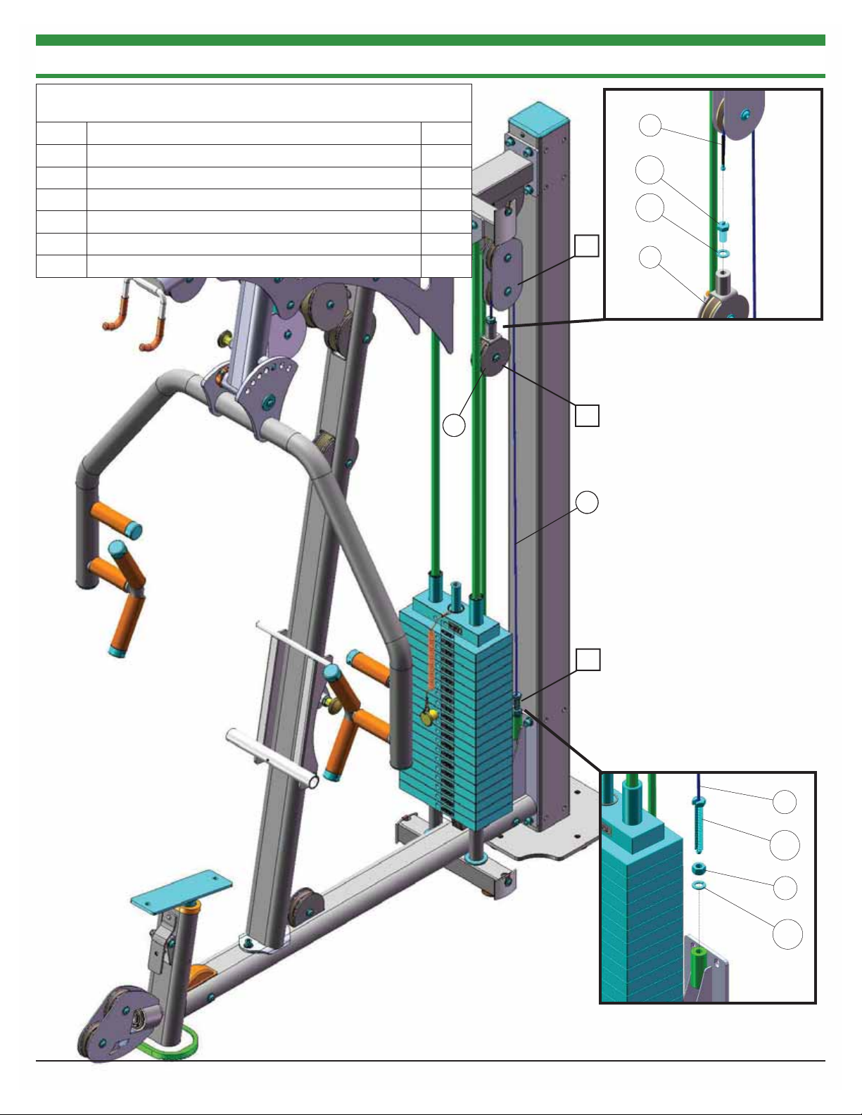
STEP 10 TENSION CABLE
Assembly List
Item # Description Qty.
9 FLOATING PULLEY BRACKET (3 1/2 PULLEY) 1
24 TENSION CABLE 1
63 FINISHED HEX NUT N/P 1/2-13 1
101 SPLIT BOLT GR-8 N/P 1/2-13 X 1 (RND CUT) 1
102 SPLIT HEX TAP BOLT GR-8 N/P 1/2-13 X 3 1/2 1
103 SPLIT LOCK WASHER N/P 1/2” 2
B
24
24
101
101
103
103
9
9
9
A
24924
C
24
24
102
102
63
63
103
103
NOTES:
1. SOME PARTS CUT OUT/NOT SHOWN FOR CLARITY.
2. LETTERS INDICATE HOW TO RUN THE CABLE.
AP-7000 SERIES MULTI PRESS STATION14
Page 15

STEP 11 ABDOMINAL CRUNCH CABLE
93
94
94
93
107
107
70
70
105
105
Assembly List
Item # Description Qty.
1 ABDOMINAL CRUNCH CABLE 1
52 COIL CHAIN N/P 3/16 X 12” LONG 1
70 HARD PVC CABLE STOPPER 1 1/2 RD X 2 2
72 LEATHER ANKLE STRAP (PART # H900A) 1
73 LOW ROW BAR 1 1/4 ALUMINUM 1
79 PLASTIC INSERT CAP 1 1/4” RD 11 GA 2
93 SHOULDER BOLT N/P 3/8 X 3/4 CUSTOM 2
94 SNAP LINK N/P 8MM X 80MM 3
105 STRAP BRACKET 20 #SF20 STAINLESS STEEL 2
107 TRICEP ROPE (#MTR) 1
116 NYLON D HANDLE 1
93
93
72
72
73
73
94
94
105
105
1
1
52
52
70
70
116
116
A
D
1
1
G
94
94
73
73
79
79
72
72
AP-7000 SERIES MULTI PRESS STATION 15
F
NOTES:
1. SOME PARTS CUT OUT/NOT SHOWN FOR CLARITY.
2. LETTERS INDICATE HOW TO RUN THE CABLE.
B
C
E
Page 16

38
38
77
77
38
38
77
77
66
66
46
46
66
66
46
46
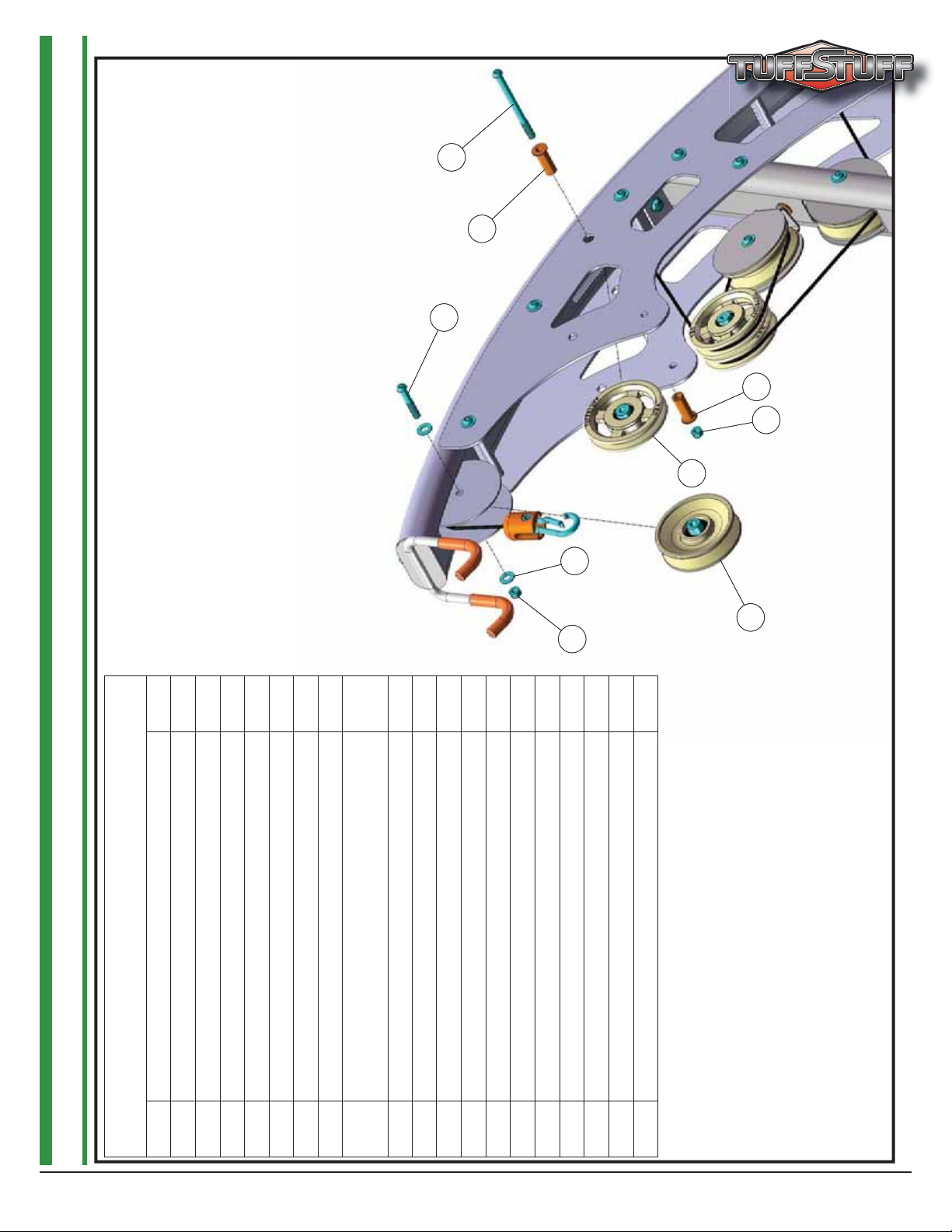
STEP 12 ABDOMINAL CRUNCH CABLE FINAL STEP
Assembly List
38 BLACK NYLON PULLEY 3/8 X 1 X 3 1/2 2
46 BUTTON HEAD SCREW GR-8 N/P 3/8-16 X 1 3/4 2
66 FLAT WASHER SAE N/P 3/8” 4
77 NYLON INSERT LOCK NUT N/P 3/8-16 2
Item # Description Qty.
AP-7000 SERIES MULTI PRESS STATION16
Page 17

STEP 13
64
64
28
28
110
110
67
67
67
67
Assembly List
Item # Description Qty.
28 WEIGHT SHIELD 2
44 BUTTON HEAD SCREW GR-8 N/P 1/4-20 X 3/4 4
67 FLAT WASHER USS N/P 1/4” 4
110 WEIGHT STACK LID 1
28
28
44
44
17AP-7000 SERIES MULTI PRESS STATION
Page 18

STEP 14
115
115
104
104
69
69
Assembly List
Item # Description Qty.
5 BACK PAD 1
10 FOOT ROLL (1 X 5 1/2 X 9) 2
11 FOOT ROLL TUBE 1 X 28 3/8 1
20 SEAT PAD 1
66 FLAT WASHER SAE N/P 3/8” 4
69 FLAT WASHER N/P 3/8 ID X 1 1/2 OD X 3/16 2
74 METAL HINGE 2
75 NYLON FLAT WASHER 1 X 1 1/4 X 1/16 2
87 RUBBER BUMPER W/WASHER 3/8 X 1 1/2 1
98 SOCKET SET SCREW ALLOY 1/4-20 X 1/4 1
104 SPLIT LOCK WASHER N/P 3/8” 2
115 BUTTON HEAD SCREW GR-8 N/P 3/8-16 X 1 1/4 7
10
10
20
20
75
75
11
11
5
5
87
87
115
115
115
115
74
74
98
98
66
66
66
66
74
74
115
115
NOTES:
1. SOME PARTS CUT OUT/NOT SHOWN FOR CLARITY.
18
75
75
10
10
69
69
104
104
115
115
AP-7000 SERIES MULTI PRESS STATION
Page 19

77
6
45
45
2727
99
99
30
30
77
64
64
77
77
66
66
77
35
35
37
37
19
19
35
66
66
104
104
35
40
40
69
69
115
115
80
80
77
77
83
83
40
40
100
100
119
119
104
104
69
69
16
16
17
17
66
66
104
104
119
119
33
33
30
30
6456456
19
95
95
95
95
99
99
31
31
99
99
31
31
90
90
91
91
90
90
18
18
99
99
91
91
31
31
20
20
4
4
66
66
100
100
69
69
104
104
119
119
5
5
115
115
60
60
76
76
65
65
77
77
66
66
26
78
78
49
49
11
11
115
115
87
87
76
76
98
98
26
77
77
66
66
39
39
32
32
99
99
66
66
65
65
2
2
75
75
10
10
66
66
77
77
77
77
38
38
7
7
77
66
66
77
77
66
66
82
82
77
77
66
66
14
14
77
77
36
36
10
10
32
32
74
74
65
65
69
69
104
104
115
115
77
77
77
77
3
3
34
34
84
84
86
86
46
46
AP-7000 SERIES MULTI PRESS STATION
77
77
114
114
97
97
97
29
29
45
45
104
104
66
66
48
48
36
36
66
66
99
99
75
75
115
115
43
43
41
41
96
96
66
66
81
81
38
38
66
66
34
34
77
77
77
77
23
23
41
41
48
48
77
77
12
12
66
66
66
66
47
47
89
89
97
38
38
69
69
78
78
66
66
50
50
99
99
83
83
41
41
66
66
104
104
77
77
109
109
38
38
50
50
46
46
66
66
110
110
109
109
77
77
77
77
27
66
112
112
13
13
111
111
68
68
68
68
66
62
62
25
25
66
66
26
51
51
8
8
113
113
26
114
114
51
51
65
65
51
64
64
42
42
51
51
66
66
38
38
66
66
9
9
38
38
6
6
66
66
50
50
46
46
51
66
66
51
51
8
8
46
46
21
21
66
66
46
46
28
28
44
44
66
66
65
65
41
41
76
76
66
66
50
50
36
36
66
66
77
77
77
77
38
38
108
108
77
77
66
66
78
78
51
51
67
67
27
77
77
66
66
46
46
46
46
92
92
38
38
44
44
28
88
88
22
22
28
67
67
Page 20

AP-71MP REV0
R
R
E
4
8
8
2
Y
Y
A
S
R
COLOR CHART
GRAY= SUB-ASSEMBLY PARTS
BLACK= HARDWARE
P-71MP
AP-71MP REV0
Parts List
Item No. Description Rev. Part No. Qty. Item No. Description Part No. Qty.
1 ABDOMINALȱCRUNCHȱCABLE 0 UP6263 1 61 DECALȬWARNINGȱDOȱNOTȱUSEȱFORȱCHINNING...ȱ(REVȱ0)ȱ BNH1890 1
2 ADJUSTABLEȱBACKȱPADȱBRACKET 0
3 ADJUSTABLEȱRELEASEȱHANDLE 0
4 ADJUSTABLEȱSEATȱFRAME 0
5 BACKȱPAD 0
6 BASEȱFRAME 0
7 BOTTOMȱSWIVELȱPULLEYȱBRACKET 0
8 DOUBLEȱPULLEYȱPLATEȱ(3ȱ1/2ȱPULLEY) 0
9 FLOATINGȱPULLEYȱBRACKETȱ(3ȱ1/2ȱPULLEY) 0
10 FOOTȱROLLȱ(1ȱXȱ5ȱ1/2ȱXȱ9)ȱȱ 0
11 FOOTȱROLLȱTUBEȱ1ȱXȱ28ȱ3/8ȱȱȱȱȱȱȱȱȱȱȱȱȱȱȱȱȱȱ 0
12 FRONTȱUPRIGHT 0
13 GUIDEȱRODS 0
14 LATȱBARȱHOLDER 0
15 LATȱCABLE 0 UP6262 1 75 NYLONȱFLATȱWASHERȱ1ȱXȱ1ȱ1/4ȱXȱ1/16 BNH0393 2
16 PIVOTȱAXLEȱ1ȱXȱ5ȱ3/4 0
17 PRESSȱBAR 0
18 PRESSȱBARȱHANDLEȱȱ 0
19 PRESSȱBARȱHOUSING 0
20 SEATȱPAD 0
21 SELECTORȱPINȱW/COILȱ3/8ȱXȱ4ȱGOLDȱKNOB 0
22 SPACERȱ1ȱ1/4ȱODȱXȱ1ȱIDȱXȱ3ȱ3/4 0
23 SWIVELȱPULLEYȱBRACKET 0 UP6261
24
TENSIONȱCABLE
25 TOPȱFRAME 0
26 TOPȱFRAMEȱREINFORCEMENTȱPLATE 0
27 TOPȱGUIDEȱRODȱ
28 WEIGHTȱSHIELD 0
29 CABLEȱRETAINERȱBRACKETȱ3ȱ1/2ȱPULLEYȱ(1/8ȱTHICK) 0 UP7083 1 89 RUBBERȱFOOTȱFORȱ6ȱXȱ4ȱ1/4ȱPLAT
30 GUIDEȱRODȱ1/2ȱRDȱXȱ66ȱ3/4 0 UP6210 1 90 RUBBERȱGRIPȱ1.1875ȱIDȱXȱ.125ȱXȱ4ȱ1/
ALUMINUMȱCAPȱ1.270ȈȱRD
31
ALUMINUMȱFOOTȱROLLȱCAPȱ1ȱ5/16ȱIDȱXȱ4ȱ1/2ȱODȱXȱ3/4
32
ALUMINUMȱINSERTȱCAPȱ2ȈȱRD
33
BALLȱBEARINGȱ#Wȱ516
34
35
BEARINGȱ6203ȱW/BUSHING
BLACKȱNYLONȱPULLEYȱ3/8ȱXȱ1ȱ1/2ȱXȱ4ȱ1/2ȱ(V3700)
36
BEARINGȱSPACERȱ2ȱ7/8Ȉ
37 BNH1941 1 97 SOCKETȱCAPȱSCREWȱGRȬ8ȱN/Pȱ3/8Ȭ16ȱXȱ3
BLACKȱNYLONȱPULLEYȱ3/8ȱXȱ1ȱXȱ3ȱ1/2ȱ(P
38
39 BNH1818
BLACKȱRUBBERȱGRIPȱ1/2ȱXȱ4ȱ7/8
40
BRONZEȱBUSHINGȱ1ȱXȱ1ȱ1/4ȱXȱ3/4ȱXȱ1ȱ1/2ȱXȱ1/8
41
BRONZEȱBUSHINGȱ1/2ȱXȱ5/8ȱXȱ1/2ȱXȱ7/8ȱXȱ1/8
42
BUTTONȱHEADȱSOCKETȱCAPȱSCREWȱGRȬ8ȱN/Pȱ1/2Ȭ13ȱXȱ5
BUTTONȱHEADȱSOCKETȱCAPȱSCREWȱGRȬ8ȱN/P
43
44
BUTTONȱHEADȱSOCKETȱCAPȱSCREWȱGRȬ8ȱN/Pȱ1/4Ȭ20ȱXȱ3/4
45
BUTTONȱHEADȱSOCKETȱCAPȱSCREWȱGRȬ8ȱN/Pȱ3/8Ȭ16ȱXȱ1
46
BUTTONȱHEADȱSOCKETȱCAPȱSCREWȱGRȬ8ȱN/Pȱ3/8Ȭ16ȱXȱ1ȱ3/4ȱȱȱȱȱ
47
BUTTONȱHEADȱSOCKETȱCAPȱSCREWȱGRȬ8ȱN/Pȱ3/8Ȭ
48
BUTTONȱHEADȱSOCKETȱCAPȱSCREWȱGRȬ8ȱN/Pȱ3/8Ȭ16ȱXȱ2ȱ1/4ȱȱȱȱȱ
49
BUTTONȱHEADȱSOCKETȱCAPȱSCREWȱGRȬ8ȱN/Pȱ3/8Ȭ16ȱXȱ2ȱ3/4ȱȱȱȱȱ
50
BUTTONȱHEADȱSOCKETȱCAPȱSCREWȱGRȬ8ȱN/Pȱ3/8Ȭ16ȱXȱ4ȱ1/2ȱȱȱȱȱ
51
BUTTONȱHEADȱSOCKETȱCAPȱSCREWȱGRȬ8ȱN/Pȱ3/8Ȭ16ȱXȱ5ȱȱȱȱȱȱȱȱȱȱȱ
52 BNH2522 2 112 10ȱLBȱTOPȱPLATEȱW/ADJȱSLTRȱBARȱ19ȱBLKȱWTSȱASS
COILȱCHAINȱN/Pȱ3/16ȱXȱ12
DECALȬADJUSTMENTȱBACKȱPADȱȱȱȱȱȱȱȱȱȱȱ
53 BNH2500 1 113 NYLONȱBUSHINGȱ1/2ȱIDȱXȱ1ȱODȱXȱ1 BNH2456 1
DECALȬADJUSTMENTȱPRESSȱBA
54 BNH2499 1 114 FLANGEDȱSPACERȱN/Pȱ.431ȱXȱ.617ȱXȱ1.602ȱ(1.517)ȱXȱ.089 BNH2515 2
DECALȬCAUTIONȱWEIGHTȱ
55 BNH0126 1 115 BUTTONȱHEADȱSOCKETȱCAPȱSCREWȱGRȬ8ȱN/Pȱ3/8Ȭ16ȱXȱ1ȱ1/4 BNH2521 7
56 BNH0142 2 116 NYLONȱDȱHANDLE BNH1215 1
DECALȬDANGERȱTIGHTENȱTHISȱRETAINING...ȱ(REVȱ2)
57 BNH2460 1 117 DECALȱWARRANTYȱLIMITEDȱ6.5ȱXȱ2 BNH2495
DECALȬEXERCISEȱBENCHȱPRES
58 BNH1893 2 118 DECALȬȱ
DECALȬIMPORTANTȱADJUSTȱCABLEȱHEREȱ(REVȱ0)
59 BNH1894 2 119 SOCKETȱCAPȱSCREWȱGRȬ8ȱN/Pȱ3/8Ȭ16ȱXȱ1 BNH2360 4
DECALȬIMPORTANTȱFORȱBESTȱPERFORMANCE...ȱ(REVȱ0)ȱȱȱȱȱȱȱ
TUFFSTUFFȱLOGOȱALUMINUMȱSMALLȱ(ADHESIVE)
60 BNH2463 2
HOUSING 0
Ȭ35375ȬH)
ȱ1/2Ȭ13ȱXȱ6ȱ1/2ȱȱȱȱȱ
16ȱXȱ2ȱ1/2ȱȱȱȱȱ
TRAININGȱSAFETY...ȱ(REVȱ1)
UP3703 1
UP7086 1
UP6197 1
UP6258 1
UP6198 1
UP6232 1
UP6229 2
UP6230 1
UP6270 2
UP6231 1
UP6200 1
UP6201 2
UP3744 1
UP3796 1
UP6228 1
UP3618 2
UP3718 1
UP6259 1
UP3035 1
UP6202 2
0 UP6264
UP6203 1
UP6227 2
UP6204 1
UP6205 2
BNH0538 6
BNH1509 4
BNH2470 2
BNH0628 2
BNH0843 2
BNH1694 4
BNH0553 11
BNH0527 2
BNH0528 4
BNH2417 1
BNH2422 1
BNH2447 4
BNH2528 2
BNH2426 9
BNH2428 1
BNH2429 2
BNH2430 1
BNH2437 4
BNH2440 9
62 DECALȬWEIGHTȱNUMBERSȱREFȱTPȬ10ȱ(200ȱlbs)ȱ BNH1542 1
63 FINISHEDȱHEXȱNUTȱN/Pȱ1/2Ȭ13 BNH2516 2
64 FLANGEDȱSPACERȱN/Pȱ.431ȱXȱ.617ȱXȱ1.755ȱ(1.667)ȱXȱ
65 FLATȱWASHERȱSAEȱN/Pȱ1/2Ȉ BNH2523
66 FLATȱWASHERȱSAEȱN/Pȱ3/8Ȉ BNH2524
67 FLATȱWASHERȱUSSȱN/Pȱ1/4Ȉȱ BNH2525
68 FLATȱWASHERȱN/Pȱ3/4ȱXȱ2ȱ BNH2526 4
69
FLATȱWASHERȱN/Pȱ3/8ȱIDȱXȱ1ȱ1/2ȱODȱXȱ3/16ȱTHICKȱȱ
70 HARDȱPVCȱCABLEȱSTOPPERȱ1ȱ1/2ȱRDȱXȱ2ȱ BNH2258 3
71 LATȱBARȱ1ȱ1/4ȱALUMINUMȱȱȱȱȱȱȱȱȱȱȱȱȱȱȱȱȱȱȱȱȱ
72 LEATHERȱ
73 LOWȱROWȱBARȱ1ȱ1/4ȱALUMINUM BNH1771 1
74 METALȱHINGE
76 NYLONȱINSERTȱLOCKȱNUTȱN/Pȱ1/2Ȭ13ȱȱȱȱȱȱȱ
77 NYLONȱINSERTȱ
78 NYLONȱPULLEYȱ3/8ȱXȱ1ȱXȱ4ȱ1/2ȱBLACK
79
PLASTICȱINSERTȱCAPȱ1ȱ1/4ȈȱRDȱ11ȱGA
80 PLASTICȱINSERTȱELLIPTICALȱGUIDEȱ(2X4)ȱȱȱ
81
PLASTICȱPULLEY
82 PLASTICȱSTOPPE
83 PULLȱPINȱ1/2ȱXȱ5ȱ5/8ȱLIGHTȱSPRINGȱ(YELLOWȱKNOB)
1
84 PULLȱPINȱSTIFFȱSPRINGȱ17/32ȱXȱ1ȱ1/2ȱKȬ105SS BNH0519 1
1
85 DECALȬMAINTENANCE BNH2226 1
86 RETAININGȱSNAPȱRINGȱEXT.ȱPLAINȱ.925ȱXȱ1ȱXȱ.042
87 RUBBERȱBUMPERȱW/WASHERȱ3/8ȱXȱ1ȱ1/2
88 RUBBERȱDONUTȱ3/4ȱXȱ2ȱ1/2
91 RUBBERȱGRIPȱ1.1875ȱIDȱXȱ.125ȱXȱ5ȱ
92 RUBBERȱGROMMETȱ3/4ȈȱID
93 SHOULDERȱBOLTȱN/Pȱ3/8ȱXȱ3/4ȱCUSTOM BNH2487 3
94 SNAPȱLINKȱN/Pȱ8MMȱXȱ80MMȱȱȱȱȱȱȱȱȱȱȱȱȱȱȱȱȱȱȱȱȱȱȱȱȱȱȱȱȱȱ BNH2517 5
95 SOCKETȱCAPȱSCREWȱGRȬ8ȱN/Pȱ1/4Ȭ28ȱXȱ3/4
96 SOCKETȱCAPȱSCREWȱGRȬ8ȱN/P
98 SOCKETȱSETȱSCREWȱN/Pȱ1/4Ȭ20ȱXȱ3/
99 SOCKETȱSETȱSCREWȱN/Pȱ10Ȭ32ȱXȱ1/
2
100 SPLITȱCOLLARȱ1Ȉȱ(PAINTED) BNH2462 2
101 SPLITȱBOLTȱGRȬ8ȱN/Pȱ1/2Ȭ13ȱXȱ1ȱ(RNDȱCUT) BNH2478 1
102 SPLITȱHEXȱTAPȱBOLTȱGRȬ8ȱN/Pȱ1/2Ȭ13ȱXȱ3ȱ1/
103 SPLITȱLOCKȱWASHERȱN/Pȱ1/2Ȉ BNH2519 3
104 SPLITȱLOCKȱWASHERȱN/Pȱ3/8Ȉ BNH2520
105 STRAPȱBRACKETȱ20ȱ#SF20ȱSTAINLESSȱSTEELȱȱ BNH0562 3
106 SUPERȱLUBEȱTEFLONȱLUBRICANTȱ82340 BNH0704 2
107 TRICEPȱROPEȱ(#MTR)ȱȱ BNH1628 1
108 RUBBERȱBUMPERȱ2Ȉȱȱ
109 UȬSTYLEȱTAPPEDȱHOLEȱNUTȱ1/4Ȭ20
110 WEIGHTȱSTACK
111 10ȱLBȱSTEELȱWEIGHTȱPLATEȱBLACKȱ4ȱ9/16ȱXȱ9ȱ7/16ȱASS
ANKLEȱSTRAPȱ(PARTȱ#ȱH900A)ȱȱ BNH1231 1
LOCKȱNUTȱN/Pȱ3/8Ȭ16
ȱCOVE
ȱ3/8Ȭ16ȱXȱ1ȱ1/4 BNH2362
ȱLID
SERIALȱNO.ȱ(APȬ71MP) BNH2540 1
.089 BNH2536
BNH2396 6
BNH1770 1
BNH0046 2
BNH2451 3
BNH2450 30
BNH0506 4
BNH0573
BNH1760 1
BNH2453
BNH1765 1
BNH0701 2
BNH0419 1
BNH0514 1
BNH0068 2
BNH1647 1
BNH0936 4
BNH1809 4
BNH0401 2
BNH2389 4
BNH2369 4
BNH2503 1
BNH2518
BNH2527 2
BNH2486 2
BNH0708 4
BNH1693 1
BNH1650 19
BNH1982 1
2
5
71
4
4
1
2
23
9
1
AP-7000 SERIES MULTI PRESS STATION 20
Page 21

Maintenance
TuffStuff Basic Strength Equipment Safety and General Maintenance
All TUFFSTUFF strength equipment is designed and manufactured to offer maximum, long-life service
with minimal maintenance. However, safety inspection and routine maintenance in your facility should be
the upmost importance in your daily operation. Information presented in these pages will serve as a basic
guideline to design your own inspection procedures.
Part One: General Inspection and Cleaning
Equipment should be wiped down with a damp cloth and dried on a daily basis. The powder coat fi nish
should be polished with a good car wax on a monthly basis. A daily wipe down of the upholstery with a lanolin based hand cleaner or Naugahyde Cleaner. Do not use cleaners such as Lysol or Windex as they will
dry out and crack the vinyl. Lanolin hand cleaner dissolves the sweat and lubricates the vinyl, maintaining
its natural fl exibility. Sweat is corrosive and when left on the frame and components will eventually cause
corrosion or rust. When performing these cleaning sessions, it is the perfect time to inspect the equipment
and note any problems for the maintenance personnel to correct.
1. Check equipment if it is operating properly.
2. Check the cable for loose fi ttings or frayed cable and is seating properly on the pulleys and
cams.
3. Make sure that the proper weight stack selector pin is with each machine and that the pin functions properly.
4. If something appears loose be sure to have it tightened immediately.
5. If a piece of equipment appears damaged or not operation properly, place the piece out-of-service immediately.
Part Two: Maintenance
In this paragraph, we will discuss the inspection of the cables, pulleys and their associated components. If
there exists the potential for injury to occur on a machine, it will most likely lie in the cable system. It is important to inspect the cables frequently and let it be known to all users that it is their responsibility to report
any worn-out cable to prevent a sudden failure that can result in an injury. Cables are moving parts, meaning cable-wear will occur regardless of the type or size used. In the advent of the 3/16” mill-spec cable this
wear takes longer to become apparent and this is why frequent inspections are so important.
1. Check the cable termination at the weight stack. To perform any cable tension adjustment,
loosen the hex jam nut and thread the hex tap bolt in or out to give cable the proper tension.
Re-tightened the hex jam nut when adjustment is complete and make sure the hex tap bolt is
threaded 1/2” into the socket of the selector bar top plate.
2. Check the cable as it terminates at the cam. Check the end fi tting for any signs of fraying in this
area. Inspect the bolt and nut and/or screw holding the fi tting and be sure that it is tight.
3. Check the cables as it passes over all pulley wheels. Visually inspect the cables and pulleys. A
cable that is wearing will exhibit a ballooned surface that passes over the pulley. This is and early
warning sign to replace the cable.
21
AP-7000 SERIES MULTI PRESS STATION
Page 22

Maintenance
Part Three: Lubrication
Bearing and linear bearings systems have advanced over the years but they must be maintained on a regular basis if you expect them to last and perform effi ciently. TuffStuff uses only the highest quality bearings
and linear motion components that are virtually trouble-free but requires the regular preventive maintenance
to insure long-lasting performance.
1. Bronze and nylon bushings, we recommend on a monthly basis to spray a tefl on-base lubricant
(silicone-free) directly onto the shaft as it passes through these bushings. Spray a small amount
onto the shaft and rotate it through its complete movement and wipe off any excess.
2. Weight stack guide rods and bushings, again use tefl on spray lubricant and this time spray onto
a rag and wipe the guide rods down with this rag on a weekly basis. Do not use WD-40 or other
lubricants as they attract dirt and will crate a mess between the weight plates and bushings.
3. Sealed bearings pivot points, as the name implies are protected from the outside environment
and require no lubrication. During the machine wipe down, wipe the external bearing surfaces
with the damp rag and dried to prevent the build up of dust and sweat.
4. Linear bearing systems are precision, high load components that require regular maintenance.
Dirt and corrosion are the major culprits in linear bearing failure. The hardened shafts must be
wiped down weekly and lubricated with a light layer of tefl on grease. We recommend a tefl onbase (silicone-free) gel/grease for this purpose. Lack of care and maintenance will result in corrosion of the linear shaft causing the bearings to clogged and jammed
If you religiously perform the maintenance procedures, you will increase the life of the machine and ultimately lower your maintenance costs with fewer replaced components and downtime.
Any doubts, equipment with mechanical problems should be placed “Out-of-Service” until all problems are
corrected. If replacement parts are required or maintenance questions, please contact:
.
TuffStuff Fitness Equipment, Inc.
Service Department
1325 E. Franklin Avenue
Pomona, CA 91766
1-800-961-9377
e-mail: service@tuffstuff.net
AP-7000 SERIES MULTI PRESS STATION
22
Page 23

DO NOT DISCARD THIS MANUAL
T U F F S T U F F L I M I T E D W A R R A N T Y
TuffStuff Fitness Equipment, Inc.
TuffStuff warrants to the original purchaser that TuffStuff equipment will be free from defects in material and
workmanship. All warranty periods begin to run from the date of delivery to the original purchaser. The warranty
and remedies set forth herein are conditioned upon proper storage, installation, use and maintenance and conformance with any recommendations of TuffStuff. This warranty does not cover products not manufactured by
TuffStuff or products which are altered without the express written consent of TuffStuff. This warranty as specified:
WARRANTY: a) Frames, welds, cams and weight plates -- Lifetime, b) Pivot bearings, pulleys, bushings, gas
shocks and guide rods -- Five (5) years, c) Belts, linear bearings and pull-pin components -- One (1) year, and
d) Upholstery, cables, finish and rubber grips -- Six (6) months, and all other parts not mentioned elsewhere in
this warranty will expire one (1) year from the date of delivery to the original purchaser. The obligation of
TuffStuff under this warranty is limited to repairing or replacing warranted defective parts, as TuffStuff may
elect, at TuffStuff’s facility in Pomona, California, without charge to purchaser for either parts or labor. Purchaser is responsible for installation of repaired or replaced parts, and all transportation and insurance costs on
returned or replaced equipment to and from TuffStuff’s facility in Pomona.
THE FOREGOING SHALL CONSTITUTE THE SOLE REMEDY OF THE PURCHASER AND THE
SOLE LIABILITY OF TUFFSTUFF WITH REGARD TO WARRANTY. NO IMPLIED STATUTORY
WARRANTY OR IMPLIED STATUTORY WARRANTY OF MERCHANTABILITY OR FITNESS
FOR A PARTICULAR PURPOSE SHALL APPLY. IN NO EVENT, WHETHER AS A RESULT OF
BREACH OF CONTRACT, WARRANTY, NEGLIGENCE OR OTHERWISE, SHALL TUFFSTUFF BE
LIABLE FOR SPECIAL, INCIDENTAL OR CONSEQUENTIAL DAMAGES INCLUDING, BUT NOT
LIMITED TO, LOSS OF PROFITS OR REVENUE, LOSS OF USE OF EQUIPMENT, COST OF CAPITAL, COST OF SUBSTITUTION EQUIPMENT, DOWNTIME COST, OR CLAIMS OF CUSTOMERS
OR PURCHASER FROM SUCH DAMAGE.
This written warranty is the final, complete and exclusive agreement of the parties with respect to the quality or
performance of the equipment and no action for breach of this written warranty or any implied warranty shall be
commenced more than one (1) year after the accrual of the cause of action. No modification of this warranty or
waiver of its terms shall be binding on either party unless approved in writing by an authorized representative of
the party. Contact TuffStuff Fitness Equipment, Inc. at 1325 E. Franklin Avenue, Pomona, California 91766,
before returning any defective equipment.
1325 E. Franklin Avenue
Pomona, CA 91766, USA
Ph: 909-629-1600 Fax: 909-629-4967
E-mail: service@tuffstuff.net Net: www.tuffstuff.net
 Loading...