

Page 1
AMERICA’S PREMIER EXERCISE EQUIPMENT
OWNER’S MANUAL
LEG PRESS STATION
AP-71LP Rev0
Revision Date 10-21-09
Page 2
Introduction
About the LEG PRESS STATION. Congratulations on your
new purchase of the LEG PRESS STATION. We hope you are
completely satisfi e with this pro uct an wish you many years of
en oyment.
Tuff Stuff Equipment
This Tuffstuff pro uct has een uilt to precise uality stan ar s
an has een carefully pac age to ensure that amage will not
occur uring shipment. The ome Lifetime Warranty an signature
in icating fi nal inspection has een con ucte y our line foreman
is an e pression of our confi ence in the completeness the
materials an wor manship of this pro uct.
Warranty
SEE A COP O WARRANT ON AC PAGE.
Registration Card
To avoi unnecessary elays in warranty service an to insure that
a permanent recor of your purchase is on fi le with our factory
e sure to complete the warranty registration car an sen it to
TuffStuff itness E uipment to ay.
Specifi cations
1. a imum Wt. Capacity - 200 l s.
2. Total achine Weight - 90 l s.
. ootprint LW - eight is 77 . or footprints refer to
the Center Post Rear Post Assem ly
anuals.
Prior to the Assembly of the LEG PRESS STATION
1. We a vise you to consult your local Tuff Stuff retailer if you shoul
have a uestion or pro lem regar ing the proper assem ly of
this unit.
Tool Requirements
1. One 7 com ination wrench
2. Two com ination wrench
. One 9 1 com ination wrench
. One 1 2 com ination wrench
. One 7 1 com ination wrench
. One a usta le wrench
7. One ratchet
. One soc et
9. One 9 1 soc et
10. One ru er mallet
11. Win e or househol glass cleaner
12. easuring tape
1 . tility nife
1 . The he ey alloy set inclu e in the Center Post Rear Post
o.
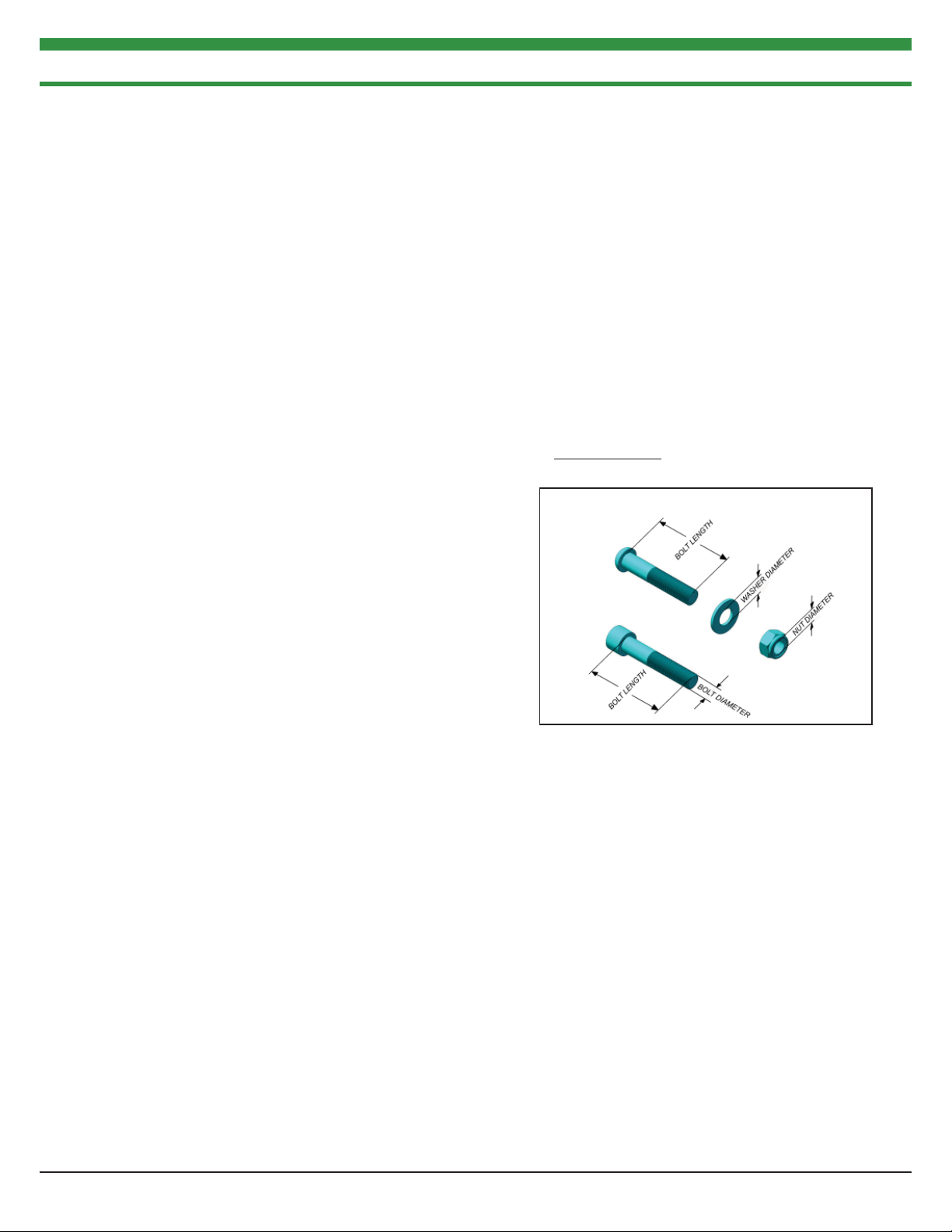
Hardware Measurement Diagram
Note: Due to continuing pro uct improvements specifi cations an esigns are su ect to change
without notice.
Safety Precautions
Safety First
Regar less of how enthusiastic you may e a out getting on
your e uipment an e ercising ta e the time to ensure that your
safety is not eopar i e . A moment s lac of attention can result
in an acci ent as can failure to o serve certain simple safety
precautions.
1. Rea stu y an un erstan the Assem ly Instructions an all the
warning la els on this pro uct. urthermore it is recommen e
to familiari e yourself an others with the proper operation an
wor out recommen ations for this Tuff Stuff pro uct prior to
use.
2. It is imperative that you retain this Assem ly Instructions an
e sure all warning la els are legi le an intact. Replacement
Assem ly Instructions an la els are availa le from your local
Tuff Stuff retailer.
. raye or worn ca les can e angerous an may cause in ury.
Perio ically chec the ca le for any in ication of wear.
. se proper iscretion when chil ren are present.
. eep han s lim s loose clothing an long hair well out of the
way of moving parts.
7. Do not attempt to lift more weight than you can control safely.
. Inspect the nit for any sign of wear on parts har ware ecoming
loose or crac s on wel s. If a pro lem is foun do not use or
allow the machine to be used until the efective part is repaire
or replace .
. Consult with your physician efore eginning any e ercise
program.
2 AP-7000 SERIES LEG PRESS STATION
Page 3

INDEX
IMPORTANT ASSEMBLY INSTRUCTION NOTE..................4
FIRST STEPS FOR A SINGLE STATION...................................5
MULTIPLE STATION ASSEMBLY STEPS.................................7
LEG PRESS CABLE......................................................................14
EXPLODED VIEW.......................................................................19
PARTS LIST...................................................................................20
MAINTENANCE.........................................................................21
AP-7000 SERIES LEG PRESS STATION 3
Page 4

IMPORTANT ASSEMBLY INSTRUCTION NOTE
INSTRUCTIONS FOR A SINGLE STATION ASSEMBLY ONLY:
FOR STEPS 1 AND 2 YOU WILL NEED SOME HARDWARE THAT IS
PROVIDED IN THE AP-70RP BOX. ONCE YOU COMPLETE STEPS
1 AND 2 SKIP TO STEP 5 TO RESUME INSTALLATION.
INSTRUCTIONS FOR A MULTI STATION ASSEMBLY ONLY:
BEGIN ASSEMBLY IN STEP 3. FOR STEPS 3 AND 4 YOU WILL
NEED SOME HARWARE THAT IS PROVIDED IN THE AP-70CP
BOX.
AP-7000 SERIES LEG PRESS STATION4
Page 5
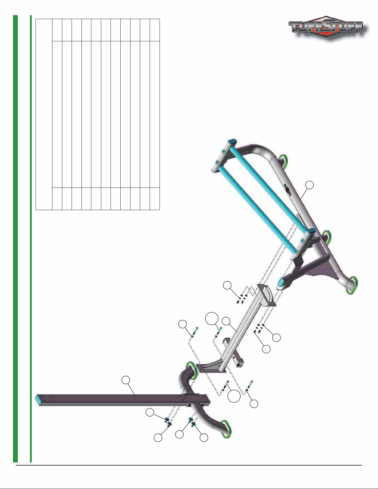
Assembly List
B7 FLAT WASHER SAE N/P 3/8” 4
B8 FLAT WASHER N/P 3/8 ID X 1 1/2 OD X 3/16 4
B1 REAR POST 1
Item # Description Qty.
B9 NYLON INSERT LOCK NUT N/P 3/8-16 4
B11 SOCKET CAP SCREW GR-8 N/P 3/8-16 X 3 4
15
15
8 CROSS BRACE 1
15 MAIN FRAME 1
48 FLAT WASHER 4
69 SOCKET CAP SCREW GR-8 N/P 3/8-16 X 3/4 4
73 SPLIT LOCK WASHER N/P 3/8” 4
73
73
8
8
B11
B7
B7
B11
STEP 1
B1
B1
B8
B8
B9
B9
B9
B9
B8
B8
48
48
69
69
B11
B11
B7
B7
5AP-7000 SERIES LEG PRESS STATION
Page 6
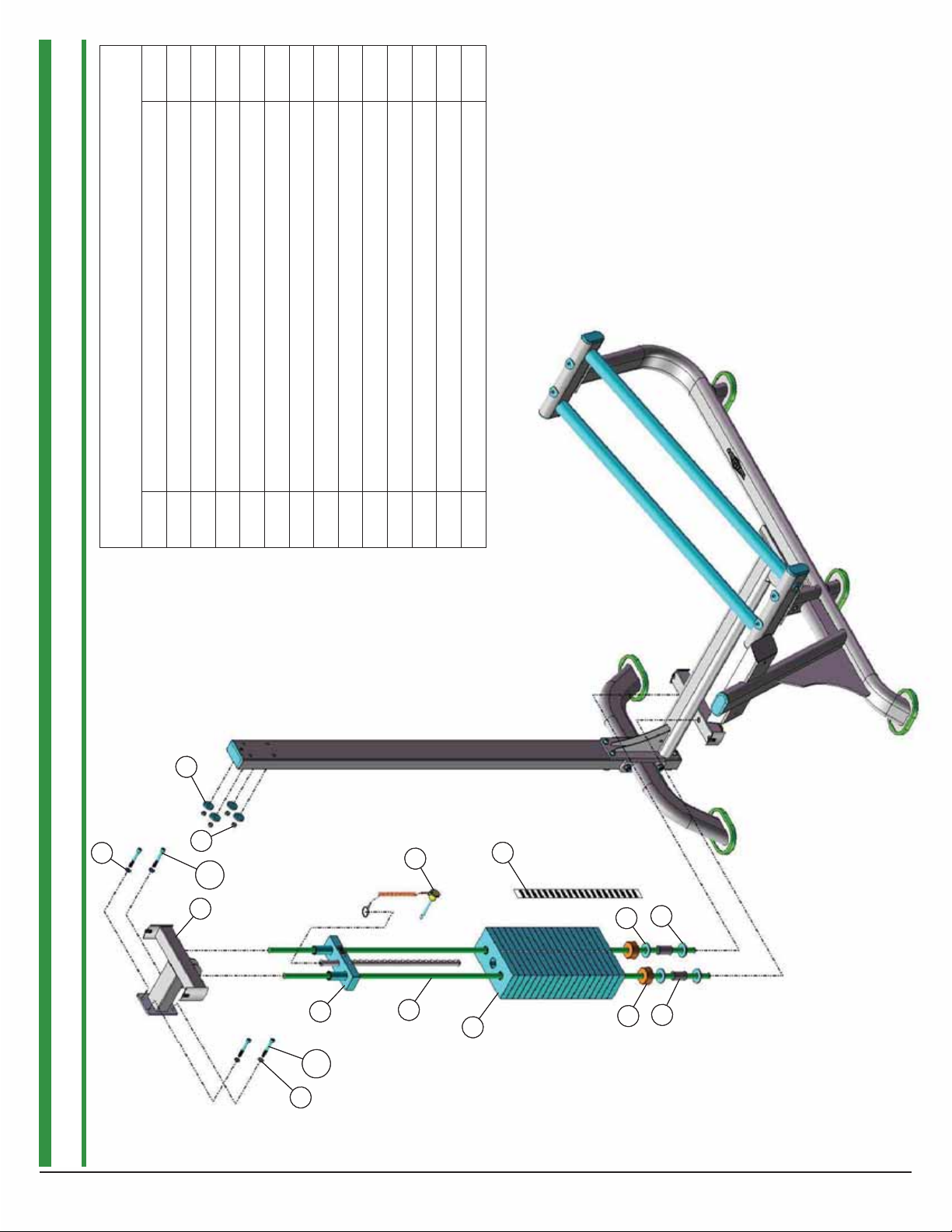
Assembly List
B7 FLAT WASHER SAE N/P 3/8” 4
B8 FLAT WASHER N/P 3/8 ID X 1 1/2 OD X 3/16 4
B9 NYLON INSERT LOCK NUT N/P 3/8-16 4
Item # Description Qty.
B8
B8
10 GUIDE RODS 3/4 RD X 71 3/4 2
B11 SOCKET CAP SCREW GR-8 N/P 3/8-16 X 3 4
17 SELECTOR PIN W/COIL 3/8 X 4 GOLD KNOB 1
18 SPACER 1 ID X 1 1/4 OD X 2 2
19 TOP GUIDE ROD HOUSING 1
21 10 LB STEEL WEIGHT PLATE BLACK 4 9/16 X 9 7/16 19
22 10 LB TOP PLATE W/ADJ SLTR BAR 19 BLK WTS 1
44 DECAL-WEIGHT NUMBERS REF TP-10 (200 lbs) 1
50 FLAT WASHER N/P 3/4 X 2 4
60 RUBBER DONUT 3/4 X 2 1/2 2
B7
B7
B9
19
19
B11
B11
B7
B7
22
22
B11
B11
10
10
17
17
21
21
44
44
50
50
60
60
50
50
18
18
B9
STEP 2
6 AP-7000 SERIES LEG PRESS STATION
Page 7
Assembly List
A7 SOCKET CAP SCREW GR-8 N/P 3/8-16 X 1 4
A1 CENTER POST 1
A8 FLAT WASHER SAE N/P 3/8” 4
Item # Description Qty.
8 CROSS BRACE 1
A10 SPLIT LOCK WASHER N/P 3/8” 4
15
15
15 MAIN FRAME 1
48 FLAT WASHER 4
69 SOCKET CAP SCREW GR-8 N/P 3/8-16 X 3/4 4
73 SPLIT LOCK WASHER N/P 3/8” 4
73
73
8
8
A10
A8
A8
A10
STEP 3
A1
A1
A10
A10
A7
A7
69
69
48
48
7AP-7000 SERIES LEG PRESS STATION
Page 8

Assembly List
A7 SOCKET CAP SCREW GR-8 N/P 3/8-16 X 1 4
A8 FLAT WASHER SAE N/P 3/8” 4
A10 SPLIT LOCK WASHER N/P 3/8” 4
A10
A10
A8
A8
A7
A7
Item # Description Qty.
10 GUIDE RODS 3/4 RD X 71 3/4 2
17 SELECTOR PIN W/COIL 3/8 X 4 GOLD KNOB 1
18 SPACER 1 ID X 1 1/4 OD X 2 2
19 TOP GUIDE ROD HOUSING 1
21 10 LB STEEL WEIGHT PLATE BLACK 4 9/16 X 9 19
22 10 LB TOP PLATE W/ADJ SLTR BAR 19 BLK WTS 1
44 DECAL-WEIGHT NUMBERS REF TP-10 (200 lbs) 1
50 FLAT WASHER N/P 3/4 X 2 4
60 RUBBER DONUT 3/4 X 2 1/2 2
17
17
44
44
19
19
A8
A8
A7
A7
A10
A10
22
22
10
10
21
21
60
60
50
50
18
18
50
50
STEP 4
8 AP-7000 SERIES LEG PRESS STATION
Page 9

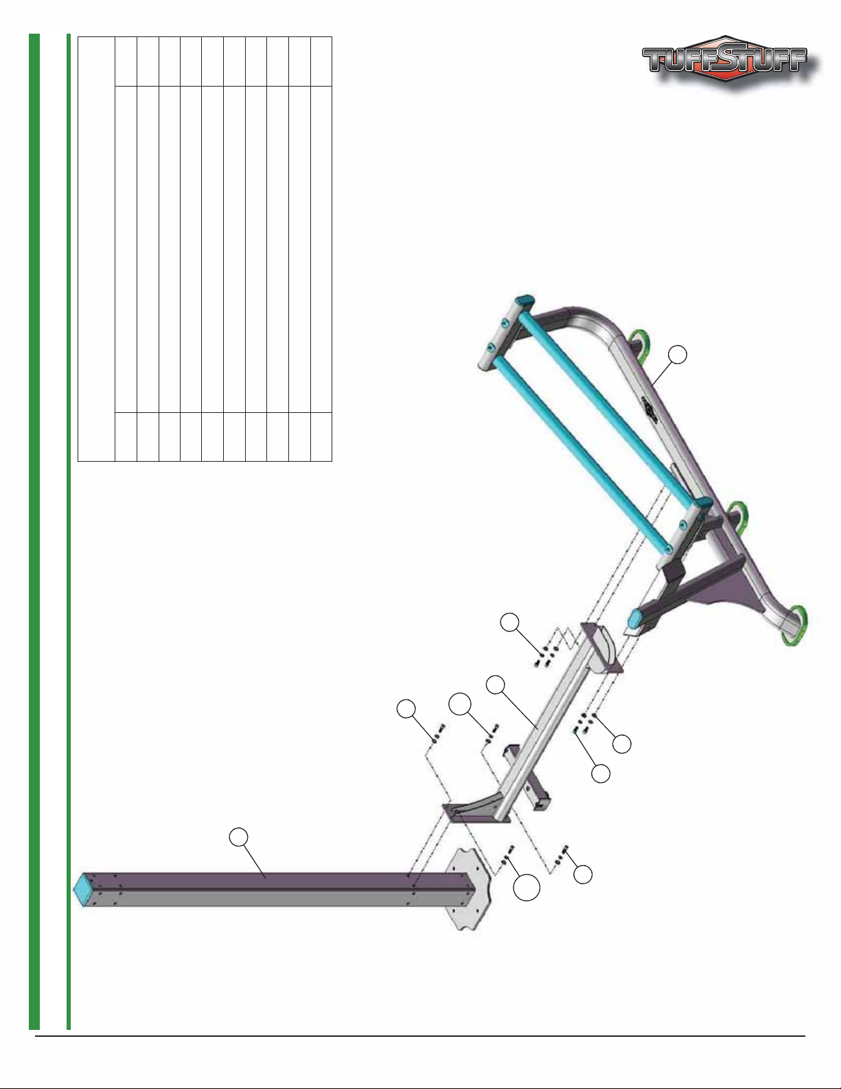
STEP 5
Assembly List
Item # Description Qty.
9 FOOT PLATE 1
48 FLAT WASHER SAE N/P 3/8” 2
52 NYLON INSERT LOCK NUT N/P 3/8-16 2
62 RUBBER FOOT PLATE COVER 1
82 FLAT HEAD SOCKET CAP SCREW B/O 3/8-16 X 3 3/16 2
62
62
82
82
48
48
9
9
52
52
AP-7000 SERIES LEG PRESS STATION
9
Page 10

STEP 6
Assembly List
Item # Description Qty.
1 ADJUSTABLE CHROME TUBE 1
4 CARRIAGE 1
32 BUTTON HEAD SCREW GR-8 N/P 3/8-16 X 1 1/4 1
34 BUTTON HEAD SCREW GR-8 N/P 3/8-16 X 1 3/4 1
45 FENDER WASHER N/P 3/8 X 2 7/8 1
48 FLAT WASHER SAE N/P 3/8” 2
52 NYLON INSERT LOCK NUT N/P 3/8-16 1
54 NYLON PULLEY 3/8 X 1 X 4 1/2 BLACK 1
59 RUBBER BUMPER W/WASHER 3/8 X 1 1/2 1
52
52
48
48
54
54
34
34
1
1
4
4
45
45
59
59
32
32
10 AP-7000 SERIES LEG PRESS STATION
Page 11

STEP 7
67
67
Assembly List
Item # Description Qty.
4 CARRIAGE 1
47 FLAT WASHER SAE N/P 1/2” 2
58 RAIL WHEEL 2 1/4 RD X 3 2
67 SOCKET CAP SCREW GR-8 N/P 1/2-13 X 4 3/4 2
72 SPLIT LOCK WASHER N/P 1/2” 2
4
4
72
72
47
47
58
58
47
47
72
72
67
67
58
58
AP-7000 SERIES LEG PRESS STATION
11
Page 12

STEP 8
Assembly List
Item # Description Qty.
11 HANDLES 1
35 BUTTON HEAD SCREW GR-8 N/P 3/8-16 X 3 2
48 FLAT WASHER SAE N/P 3/8” 4
52 NYLON INSERT LOCK NUT N/P 3/8-16 2
11
11
35
35
48
48
48
48
52
52
12 AP-7000 SERIES LEG PRESS STATION
Page 13

STEP 9
Assembly List
Item # Description Qty.
5 CHROME RELEASE HANDLE 1
36 BUTTON HEAD SCREW GR8 N/P 5/16-18 X 3/4 1
66 SINGLE STRAND CONNECTING LINK #40 1
70 SOCKET SET SCREW N/P 10-32 X 1/8 1
80 FLAT WASHER USS N/P 5/16” 1
81 SPLIT LOCK WASHER N/P 5/16” 1
36
36
70
70
81
81
80
80
66
66
66
66
5
5
AP-7000 SERIES LEG PRESS STATION
13
Page 14

Assembly List
3 CABLE ADJUSTER 1
12 LEG PRESS CABLE 1
34 BUTTON HEAD SCREW GR-8 N/P 3/8-16 X 1 3/4 1
46 FINISHED HEX NUT N/P 1/2-13 1
48 FLAT WASHER SAE N/P 3/8” 2
52 NYLON INSERT LOCK NUT N/P 3/8-16 1
53 NYLON INSERT LOCK NUT N/P 5/16-18 1
54 NYLON PULLEY 3/8 X 1 X 4 1/2 BLACK 1
65 SHOULDER BOLT N/P 3/8 X 3/4 1
71 SPLIT BOLT GR-8 N/P 1/2-13 X 1 1
72 SPLIT LOCK WASHER N/P 1/2” 2
STEP 10 LEG PRESS CABLE ASSEMLY
14 AP-7000 SERIES LEG PRESS STATION
Item # Description Qty.
74 STRAP BRACKET 20 #SF20 STAINLESS STEEL 1
Page 15

34
34
48
48
B
B
12
12
52
52
71
71
72
72
54
54
12
12
A
A
G
G
E
E
C
C
74
74
65
65
F
F
12
12
53
53
3
3
46
46
72
72
D
D
NOTES:
1. SOME PARTS CUT OUT/NOT SHOWN FOR CLARITY.
15AP-7000 SERIES LEG PRESS STATION
Page 16

STEP 11 CABLE ASSEMBLY FINAL STEP
Assembly List
Item # Description Qty.
27 BLACK NYLON PULLEY 3/8 X 1 X 3 1/2 2
34 BUTTON HEAD SCREW GR-8 N/P 3/8-16 X 1 3/4 2
37 BUTTON HEAD SCREW GR-8 N/P 3/8-16 X 4 1/2 1
48 FLAT WASHER SAE N/P 3/8” 6
52 NYLON INSERT LOCK NUT N/P 3/8-16 3
55 NYLON PULLEY 3/8 X 1 X 6 BLACK 1
37
37
27
27
52
52
48
48
48
48
52
52
55
55
34
34
52
52
27
27
48
48
34
34
16 AP-7000 SERIES LEG PRESS STATION
Page 17

STEP 12
30
30
79
79
Assembly List
Item # Description Qty.
20 WEIGHT SHIELD 2
30 BUTTON HEAD SCREW GR-8 N/P 1/4-20 X 3/4 4
49 FLAT WASHER USS N/P 1/4” 4
79 WEIGHT STACK LID 1
49
49
20
20
49
49
20
20
30
30
17AP-7000 SERIES LEG PRESS STATION
Page 18

STEP 13
Assembly List
Item # Description Qty.
2 BACK PAD 1
16 SEAT PAD 1
32 BUTTON HEAD SCREW GR-8 N/P 3/8-16 X 1 1/4 2
35 BUTTON HEAD SCREW GR-8 N/P 3/8-16 X 3 2
48 FLAT WASHER SAE N/P 3/8” 4
2
2
16
16
48
48
32
32
48
48
35
35
18
AP-7000 SERIES LEG PRESS STATION
Page 19

2
2
70
63
63
11
70
70
23
79
79
78
78
19
19
52
52
48
48
34
34
64
64
54
54
30
30
20
20
49
49
22
22
10
10
21
21
60
60
18
18
17
17
44
44
50
50
50
50
49
49
20
20
34
34
30
30
76
76
23
70
70
16
16
67
67
67
67
72
72
47
47
24
24
52
27
27
48
48
52
31
31
76
76
52
52
78
78
69
69
55
55
73
73
48
48
11
25
48
35
35
72
72
58
58
7
7
56
56
54
54
34
34
48
48
52
52
32
32
76
76
69
69
73
73
48
48
48
4
4
47
47
48
48
58
58
1
1
32
32
56
56
48
48
34
34
8
8
25
35
35
48
48
48
48
52
52
32
32
59
59
45
45
47
47
6
6
72
72
47
47
67
67
25
25
48
48
52
52
70
57
36
36
81
81
80
80
29
29
29
29
77
77
67
67
25
25
73
73
14
14
33
33
43
43
27
27
48
48
37
37
57
66
66
5
5
28
28
77
77
13
13
38
38
58
58
48
48
51
51
15
15
61
61
48
48
52
52
13
13
58
58
52
52
82
82
38
38
33
33
73
73
14
14
51
51
25
25
62
62
9
9
19
AP-7000 SERIES LEG PRESS STATION
Page 20

AP-71LP REV0
T
E
R
7
8
L
A
P
Y
Y
S
R
0
COLOR CHART
GRAY= SUB-ASSEMBLY PARTS
BLACK= HARDWARE
P-71LP
AP-71LP REV
arts List
Item No. Description Rev. Part No. Qty. Item No. Description Part No. Qty.
1 ADJUSTABLEȱCHROMEȱTUBE 0
2 BACKȱPAD 0
3 CABLEȱADJUSTER 0
4 CARRIAGE 0
5 CHROMEȱRELEASEȱHANDLE 0
6 COVERȱPLATEȱLT 0
7 COVERȱPLATEȱRT 0
8 CROSSȱBRACE 0
9 FOOTȱPLATE 1
10 GUIDEȱRODSȱ3/4ȱRDȱXȱ71ȱ
11 HANDLES 1
12 LEGȱPRESSȱCABLE 0
13 LINEARȱRAIL 0
14 LINEARȱRAILȱHOUSING 0
15 MAINȱFRAME 1
16 SEATȱPADȱ 0
17 SELECTORȱPINȱW/COILȱ3/8ȱXȱ4ȱGOLDȱKNOB 0
18 SPACERȱ1ȱIDȱXȱ1ȱ1/4ȱODȱXȱ2ȱ 0
19 TOPȱGUIDEȱRODȱHOUSING 0
20 WEIGHTȱSHIELD 0
21 BNH1650 19 62 RUBBER FOOT PLATE COVE
10 LB STEEL WEIGHT PLATE BLACK 4 9/16 X 9 7/16 ASS
22
10 LB TOP PLATE W/ADJ SLTR BAR 19 BLK WTS ASS
23
ALUMINUM CAP 1.020Ȉ RD (CAPȬ100)
24
ALUMINUM INSERT CAP 1 X 2
25
ALUMINUM INSERT ELLIPTICAL CAP 2 X 4
DECALȬWARNING ATTENTION USERS! MAKE... (REV 0)
26 BNH2152 1 67 SOCKET CAP SCREW GRȬ8 N/P 1/2Ȭ13 X 4 1/2
27
BLACK NYLON PULLEY 3/8 X 1 X 3 1/2 (PȬ35375ȬH)
28
BLACK RUBBER GRIP 1/2 X 4
29
BRONZE BUSHING 1/2 X 5/8 X 1/2 X 7/8 X 1/8
BUTTON HEAD SOCKET CAP SCREW
30
BUTTON HEAD SOCKET CAP SCREW GRȬ8 N/P 1/4Ȭ20 X 3/8
31 BNH2474 2 72 SPLIT LOCK WASHER N/P 1/2Ȉ BNH2519 8
BUTTON HEAD SOCKET CAP SCREW GRȬ8 N/P 3/8Ȭ16 X 1 1/4
32
BUTTON HEAD SOCKET CAP SCREW GRȬ8 N/P 3/8Ȭ16 X 1 1/2
33 BNH2533
BUTTON HEAD SOCKET CAP SCREW GRȬ8
34
35
BUTTON HEAD SOCKET CAP SCREW GRȬ8 N/P 3/8Ȭ16 X 3
36 BNH2480
BUTTON HEAD SOCKET CAP SCREW GR8 N/P 5/16Ȭ18 X 3/4
37
BUTTON HEAD SOCKET CAP SCREW G
38
BUTTON HEAD SOCKET CAP SCREW GRȬ8 N/P 3/8Ȭ16 X 5
DECALȬDANGER TIGHTEN THIS RETAINING... (REV 2)
39 BNH0142 1 80 FLAT WASHER USS N/P 5/16Ȉ BNH2534 1
DECALȬEXERCISE LEG PRES
40 BNH2466 1 81 SPLIT LOCK WASHER
41 BNH1893 1 82 FLAT HEAD SOCKET CAP SCREW N/P 3/8Ȭ16 X 3 3/16 BNH2553
DECALȬIMPORTANT ADJUST CABLE HERE (REV 0)
3/4 0
GRȬ8 N/P 1/4Ȭ20 X 3/4
N/P 3/8Ȭ16 X 1 3/4
Ȭ8 N/P 3/8Ȭ16 X 4 1/2
UP6233 1
UP6234 1
UP6236 1
UP6237 1
UP6238 1
UP6239 1
UP6240 1
UP6241 1
UP6242 1
UP6201 2
UP6243 1
UP6235 1
UP6244 2
UP6245 2
UP6246 1
UP6247 1
UP3035 1
UP6267 2
UP6248 1
UP6205 2
BNH1982 1
BNH0537 2
BNH1500 1
BNH2398 6
BNH0553 2
BNH0530 1
BNH0528 2
BNH2447 4
BNH2521 3
BNH2426 4
BNH2432 4
BNH2437 1
BNH2440 4
42 DECALȬIMPORTANT FOR BEST PERFORMANCE... (REV 0) BNH1894 2
43 TUFFSTUFF LOGO ALUMINUM SMALL (ADHESIVE) BNH2463 1
44 DECALȬWEIGHT NUMBERS REF TPȬ10 (200 lbs) BNH1542 1
45 FENDER WASHER N/P 3/8 X 2 7/8 BNH2532
46 FINISHED HEX NUT N/P 1/2Ȭ13 BNH2516 1
47 FLAT WASHER SAE N/P 1/2Ȉ BNH2523
48 FLAT WASHER SAE N/P 3/8Ȉ BNH2524
49 FLAT WASHER USS N/P 1/4Ȉ BNH2525
50 FLAT WASHER N/P 3/4 X 2 BNH2526 4
51 FLAT WASHER N/P 3/8
52 NYLON INSERT LOCK NUT N/P 3/8Ȭ16
53 NYLON INSERT LOCK NUT N/P 5/16Ȭ18 BNH2529 1
54 NYLON PULLEY 3/8 X 1 X 4 1/2 BLACK
55 NYLON PULLEY 3/8 X 1 X 6
56 PLASTIC TUBE GLIDE 2 X 1 X 8 (HF1651600 TWO PIECE SE
57 PUSH PULL PIN 1/2 X 2 9/16 DRILLED ASSY
58 RAIL WHEEL 1/2 X 2 1/4 RD X 3
59 RUBBER BUMPER W/WASHER 3/8 X 1 1/2
60 RUBBER DONUT 3/4 X 2 1/2
61 RUBBER FOOT FOR 6 X 4 1/4 PLAT
63 RUBBER GRIP 1 ID X .125 X
64 RUBBER GROMMET 3/4Ȉ ID
65 SHOULDER BOLT N/P 3/8 X 3/4 BNH2392 1
66 SINGLE STRAND CONNECTING LINK #40 (6261K193)
68 DECALȬWARNING KEEP HANDS AND FINGERS... (REV 2) BNH0620 1
69 SOCKET CAP SCREW GRȬ8 N/P 3/8
70 SOCKET SET SCREW N/P 10Ȭ32 X 1/
71 SPLIT BOLT GRȬ8 N/P 1/2Ȭ13 X 1 (RND CUT) BNH2478 1
73 SPLIT LOCK WASHER N/P 3/8Ȉ BNH2520
74 STRAP BRACKET 20 #SF20 STAINLESS STEE
4
75 SUPER LUBE TEFLON LUBRICANT 82340 BNH0704 2
76 RUBBER BUMPER 2Ȉ
77 UȬSHAPE WASHER N/P 3/8 ID X 1 1/2 OD X 3/16 THICK
1
78 UȬSTYLE TAPPED HOLE NUT 1/4Ȭ20
79 WEIGHT STACK LID
ID X 1 1/2 OD X 3/16 THICK
BLACK
Ȭ16 X 3/4
N/P 5/16Ȉ BNH2535 1
BNH2396 4
BNH2450 13
BNH0506 2
BNH2298 1
BNH1874 2
BNH1996 1
BNH2472 6
BNH0514 1
BNH0068 2
BNH1647 3
BNH1716 1
BNH0962 2
BNH0401 2
BNH0066 1
BNH2347 6
BNH2373 4
BNH2518
BNH0562 1
BNH2486 4
BNH2393 4
BNH0708 4
BNH1693 1
1
6
30
4
5
4
2
AP-7000 SERIES LEG PRESS STATION
20
Page 21

Maintenance
TuffStuff Basic Strength Equipment Safety and General Maintenance
All TUFFSTUFF strength equipment is designed and manufactured to offer maximum, long-life service
with minimal maintenance. However, safety inspection and routine maintenance in your facility should be
the upmost importance in your daily operation. Information presented in these pages will serve as a basic
guideline to design your own inspection procedures.
Part One: General Inspection and Cleaning
Equipment should be wiped down with a damp cloth and dried on a daily basis. The powder coat fi nish
should be polished with a good car wax on a monthly basis. A daily wipe down of the upholstery with a lanolin based hand cleaner or Naugahyde Cleaner. Do not use cleaners such as Lysol or Windex as they will
dry out and crack the vinyl. Lanolin hand cleaner dissolves the sweat and lubricates the vinyl, maintaining
its natural fl exibility. Sweat is corrosive and when left on the frame and components will eventually cause
corrosion or rust. When performing these cleaning sessions, it is the perfect time to inspect the equipment
and note any problems for the maintenance personnel to correct.
1. Check equipment if it is operating properly.
2. Check the cable for loose fi ttings or frayed cable and is seating properly on the pulleys and
cams.
3. Make sure that the proper weight stack selector pin is with each machine and that the pin functions properly.
4. If something appears loose be sure to have it tightened immediately.
5. If a piece of equipment appears damaged or not operation properly, place the piece out-of-service immediately.
Part Two: Maintenance
In this paragraph, we will discuss the inspection of the cables, pulleys and their associated components. If
there exists the potential for injury to occur on a machine, it will most likely lie in the cable system. It is important to inspect the cables frequently and let it be known to all users that it is their responsibility to report
any worn-out cable to prevent a sudden failure that can result in an injury. Cables are moving parts, meaning cable-wear will occur regardless of the type or size used. In the advent of the 3/16” mill-spec cable this
wear takes longer to become apparent and this is why frequent inspections are so important.
1. Check the cable termination at the weight stack. To perform any cable tension adjustment,
loosen the hex jam nut and thread the hex tap bolt in or out to give cable the proper tension.
Re-tightened the hex jam nut when adjustment is complete and make sure the hex tap bolt is
threaded 1/2” into the socket of the selector bar top plate.
2. Check the cable as it terminates at the cam. Check the end fi tting for any signs of fraying in this
area. Inspect the bolt and nut and/or screw holding the fi tting and be sure that it is tight.
3. Check the cables as it passes over all pulley wheels. Visually inspect the cables and pulleys. A
cable that is wearing will exhibit a ballooned surface that passes over the pulley. This is and early
warning sign to replace the cable.
21
AP-7000 SERIES LEG PRESS STATION
Page 22

Maintenance
Part Three: Lubrication
Bearing and linear bearings systems have advanced over the years but they must be maintained on a regular basis if you expect them to last and perform effi ciently. TuffStuff uses only the highest quality bearings
and linear motion components that are virtually trouble-free but requires the regular preventive maintenance
to insure long-lasting performance.
1. Bronze and nylon bushings, we recommend on a monthly basis to spray a tefl on-base lubricant
(silicone-free) directly onto the shaft as it passes through these bushings. Spray a small amount
onto the shaft and rotate it through its complete movement and wipe off any excess.
2. Weight stack guide rods and bushings, again use tefl on spray lubricant and this time spray onto
a rag and wipe the guide rods down with this rag on a weekly basis. Do not use WD-40 or other
lubricants as they attract dirt and will crate a mess between the weight plates and bushings.
3. Sealed bearings pivot points, as the name implies are protected from the outside environment
and require no lubrication. During the machine wipe down, wipe the external bearing surfaces
with the damp rag and dried to prevent the build up of dust and sweat.
4. Linear bearing systems are precision, high load components that require regular maintenance.
Dirt and corrosion are the major culprits in linear bearing failure. The hardened shafts must be
wiped down weekly and lubricated with a light layer of tefl on grease. We recommend a tefl onbase (silicone-free) gel/grease for this purpose. Lack of care and maintenance will result in corrosion of the linear shaft causing the bearings to clogged and jammed
If you religiously perform the maintenance procedures, you will increase the life of the machine and ultimately lower your maintenance costs with fewer replaced components and downtime.
Any doubts, equipment with mechanical problems should be placed “Out-of-Service” until all problems are
corrected. If replacement parts are required or maintenance questions, please contact:
.
TuffStuff Fitness Equipment, Inc.
Service Department
1325 E. Franklin Avenue
Pomona, CA 91766
1-800-961-9377
e-mail: service@tuffstuff.net
AP-7000 SERIES LEG PRESS STATION
22
Page 23

DO NOT DISCARD THIS MANUAL
T U F F S T U F F L I M I T E D W A R R A N T Y
TuffStuff Fitness Equipment, Inc.
TuffStuff warrants to the original purchaser that TuffStuff equipment will be free from defects in material and
workmanship. All warranty periods begin to run from the date of delivery to the original purchaser. The warranty
and remedies set forth herein are conditioned upon proper storage, installation, use and maintenance and conformance with any recommendations of TuffStuff. This warranty does not cover products not manufactured by
TuffStuff or products which are altered without the express written consent of TuffStuff. This warranty as specified:
WARRANTY: a) Frames, welds, cams and weight plates -- Lifetime, b) Pivot bearings, pulleys, bushings, gas
shocks and guide rods -- Five (5) years, c) Belts, linear bearings and pull-pin components -- One (1) year, and
d) Upholstery, cables, finish and rubber grips -- Six (6) months, and all other parts not mentioned elsewhere in
this warranty will expire one (1) year from the date of delivery to the original purchaser. The obligation of
TuffStuff under this warranty is limited to repairing or replacing warranted defective parts, as TuffStuff may
elect, at TuffStuff’s facility in Pomona, California, without charge to purchaser for either parts or labor. Purchaser is responsible for installation of repaired or replaced parts, and all transportation and insurance costs on
returned or replaced equipment to and from TuffStuff’s facility in Pomona.
THE FOREGOING SHALL CONSTITUTE THE SOLE REMEDY OF THE PURCHASER AND THE
SOLE LIABILITY OF TUFFSTUFF WITH REGARD TO WARRANTY. NO IMPLIED STATUTORY
WARRANTY OR IMPLIED STATUTORY WARRANTY OF MERCHANTABILITY OR FITNESS
FOR A PARTICULAR PURPOSE SHALL APPLY. IN NO EVENT, WHETHER AS A RESULT OF
BREACH OF CONTRACT, WARRANTY, NEGLIGENCE OR OTHERWISE, SHALL TUFFSTUFF BE
LIABLE FOR SPECIAL, INCIDENTAL OR CONSEQUENTIAL DAMAGES INCLUDING, BUT NOT
LIMITED TO, LOSS OF PROFITS OR REVENUE, LOSS OF USE OF EQUIPMENT, COST OF CAPITAL, COST OF SUBSTITUTION EQUIPMENT, DOWNTIME COST, OR CLAIMS OF CUSTOMERS
OR PURCHASER FROM SUCH DAMAGE.
This written warranty is the final, complete and exclusive agreement of the parties with respect to the quality or
performance of the equipment and no action for breach of this written warranty or any implied warranty shall be
commenced more than one (1) year after the accrual of the cause of action. No modification of this warranty or
waiver of its terms shall be binding on either party unless approved in writing by an authorized representative of
the party. Contact TuffStuff Fitness Equipment, Inc. at 1325 E. Franklin Avenue, Pomona, California 91766,
before returning any defective equipment.
1325 E. Franklin Avenue
Pomona, CA 91766, USA
Ph: 909-629-1600 Fax: 909-629-4967
E-mail: service@tuffstuff.net Net: www.tuffstuff.net
 Loading...