

Page 1
ASSEMBLY INSTRUCTIONS
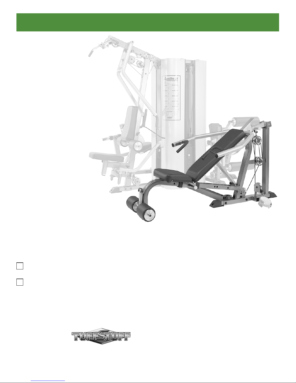
Multi-Press Station
Includes Assembly for:
AP-5MPS
Multi-Press W/Nylon Pulleys (Standard)
AP-5MPD
Multi-Press W/Aluminum Pulleys (Deluxe)
America’s Premium Exercise Equipment
Revision Date 06-28-05
AP-5MPS_AP-5MPD Rev0
Page 2
About the AP-5MPS_AP-5MPD Multi-Press Station
Congratulations on your new purchase of the AP-5MPS_AP-5MPD
Multi-Press Station. We hope you are completely satisfi ed with this
product and wish you many years of enjoyment.
Prior to the Assembly of the AP-5MPS_AP-5MPD
1. We advise you to consult your local Tuff Stuff retailer if you
should have a question or problem regarding the proper
assembly of this unit.
Tuff Stuff Equipment
This Tuffstuff product has been built to precise quality standards
and has been carefully packaged to ensure that damage will
not occur during shipment. The Limited Warranty and signature
indicating fi nal inspection has been conducted by our line foreman,
is an expression of our confi dence in the completeness, the
materials, and workmanship of this product.
Warranty
SEE A COPY OF WARRANTY ON BACK PAGE.
Registration Card
To avoid unnecessary delays in warranty service and to insure that
a permanent record of your purchase is on fi le with our factory,
be sure to complete the warranty registration card and send it to
TuffStuff Fitness Equipment today.
Specifi cations
1. Maximum Wt. Capacity - 200 lbs.
2. Total Machine Weight - 185 lbs.
2. Neatly organize and identify all parts according to the Parts List
and the Exploded View Diagram.
Tool Requirements
1. One 7/8” combination wrench
2. One 3/4” combination wrench
3. One 9/16” combination wrench
4. One 1/2” combination wrench
5. One ratchet
6. One 3/4” socket
7. One 9/16” socket
8. One rubber mallet
9. Windex or household glass cleaner
10. Measuring tape
11. Utility knife
Note: Due to continuing product improvements, specifi cations and designs are subject to change
without notice.
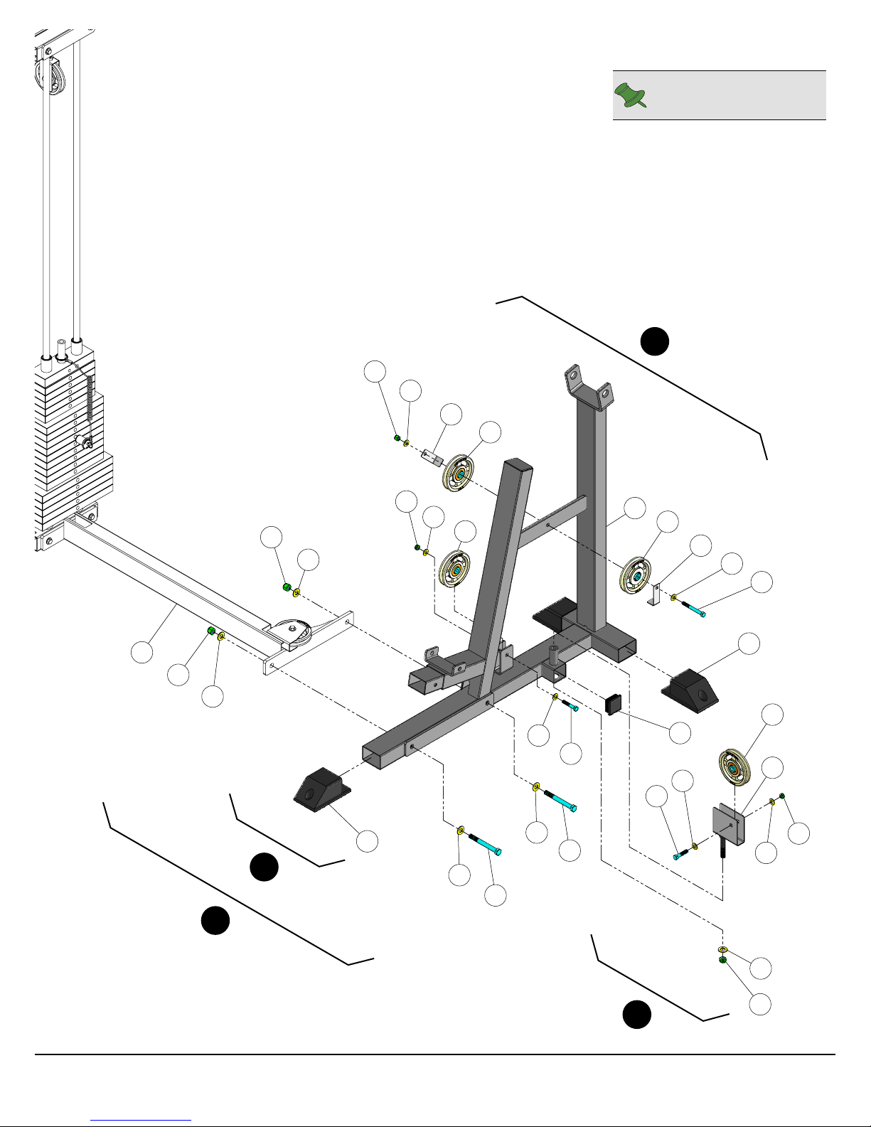
Step 1 Bottom Cross Brace Assembly
A
Assemble the Adjustable Pulley Bracket (#1) to the Weight Stack Frame using hardware shown.
Attach a Pulley 3/8 X 4 1/2 (#23) to the Weight Stack Frame using hardware shown.
B
Affi x the Bottom Cross Brace (#6) to the Weight Stack Frame using hardware shown.
C
Attach a Pulley 3/8 X 4 1/2 (#23) to the Bottom Cross Brace (#6) using hardware shown.
D
Assembly List
Item # Description Qty. Item # Description Qty.
1 ADJUSTABLE PULLEY BRACKET 1 44 HEX HEAD CAP SCREW GR-5 B/O 3/8-16 X 1 3/4 3
6 BOTTOM CROSS BRACE 1 46 HEX HEAD CAP SCREW GR-5 B/O 3/8-16 X 3 1/4 2
23 PULLEY 3/8” X 4 1/2” 2 56 NYLON INSERT JAM LOCK NUT B/O 3/8-16 3
34 FINISHED HEX NUT B/O 1/2-13 2 58 NYLON INSERT LOCK NUT B/O 3/8-16 2
37 FLAT WASHER SAE B/O 3/8” 10
80 SPLIT LOCK WASHER Z/P 1/2” 2
1
AP-5MPS_AP-5MPD Multi-Press Station
Page 3

44
B
37
23
37
56
44
Weight Stack
Frame
34
80
80
34
1
56
37
37
23
A
58
37
Weight Stack
C
Frame
37
46
58
37
D
37
46
6
Note: Some parts have
been cut away for clarity.
44
37
23
37
56
AP-5MPS_AP-5MPD Multi-Press Station
2
Page 4

Step 2 Main Frame Assembly
A
Using a rubber mallet, insert three Plastic End Caps 2 X 3 (#60) onto the tube-ends of the Main Frame (#10).
Attach the Main Frame (#10) to the Bottom Cross Brace (#6) using hardware shown.
B
Attach the Swivel Pulley Bracket (#19) to the Main Frame (#10) using hardware shown. Next, attach a Pulley
C
3/8 X 4 1/2 (#23) to the Swivel Pulley Bracket (#19) using hardware shown.
Attach three Pulleys 3/8 X 4 1/2 (#23) to the Main Frame (#10) using hardware shown.
D
Assembly List
Item # Description Qty. Item # Description Qty.
7 CABLE RETAINER BRACKET 2 45 HEX HEAD CAP SCREW GR-5 B/O 3/8-16 X 2 1
10 MAIN FRAME 1 46 HEX HEAD CAP SCREW GR-5 B/O 3/8-16 X 3 1/4 1
19 SWIVEL PULLEY BRACKET 1 55 NYLON INSERT JAM LOCK NUT B/O 1/2-13 1
23 PULLEY 3/8” X 4 1/2” 4 56 NYLON INSERT JAM LOCK NUT B/O 3/8-16 2
36 FLAT WASHER SAE B/O 1/2” 5 57 NYLON INSERT LOCK NUT B/O 1/2-13 2
37 FLAT WASHER SAE B/O 3/8” 6 58 NYLON INSERT LOCK NUT B/O 3/8-16 1
39 HEX HEAD CAP SCREW GR-5 B/O 1/2-13 X 4 1/2 2 60 PLASTIC END CAP 2 X 3 3
44 HEX HEAD CAP SCREW GR-5 B/O 3/8-16 X 1 3/4 1 62 PLASTIC INSERT CAP 2” SQ 10-14 GA 1
3
AP-5MPS_AP-5MPD Multi-Press Station
Page 5
58
Note: Some parts have
been cut away for clarity.
D
37
7
23
56
37
57
36
6
57
36
60
A
23
37
45
36
39
36
39
10
23
7
37
46
60
23
62
19
37
44
56
37
B
AP-5MPS_AP-5MPD Multi-Press Station
36
55
C
4
Page 6

Step 3 Bench Assembly
A
Insert the Slide Carriage (#16) onto the Bench Frame (#4), locking it into place with the Pull Pin 1/2 X 5 5/8 (#64).
Attach the Bench Frame (#4) to the Main Frame (#10) using hardware shown.
B
Attach one side of the Support Bar (#17) to the Main Frame (#10) using hardware shown.
C
Connect the Back Pad Frame (#3) to the Slide Carriage (#16) using hardware shown.
D
Mount the Back Pad Frame (#3) to the Support Bar (#17) and secure it into place using hardware shown.
E
Attach the Bench Seat Pad (#5) to the Slide Carriage (#16) and the Back Pad (#2) to the Back Pad Frame (#3) using
F
hardware shown.
Assemble the Foot Roll Holder (#9) to the Main Frame (#10) using hardware shown.
G
Assembly List
Item # Description Qty. Item # Description Qty.
2 BACK PAD 1 37 FLAT WASHER SAE B/O 3/8” 6
3 BACK PAD FRAME 1 38 HEX HEAD CAP SCREW GR-5 B/O 1/2-13 X 3 1/2 1
4 BENCH FRAME 1 40 HEX HEAD CAP SCREW GR-5 B/O 1/2-13 X 5 1/2 3
5 BENCH SEAT PAD 1 42 HEX HEAD CAP SCREW GR-5 B/O 3/8-16 X 1 1/2 1
8 FOAM ROLL 1 X 5 1/2 X 7 1/4 2 43 HEX HEAD CAP SCREW GR-5 B/O 3/8-16 X 1 1/4 4
9 FOOT ROLL HOLDER 1 47 HEX HEAD CAP SCREW GR-5 B/O 3/8-16 X 3 3/4 1
16 SLIDE CARRIAGE 1 55 NYLON INSERT JAM LOCK NUT B/O 1/2-13 2
17 SUPPORT BAR 1 57 NYLON INSERT LOCK NUT B/O 1/2-13 2
21 ALUMINUM COLLAR 1.0312 ID 2 58 NYLON INSERT LOCK NUT B/O 3/8-16 1
27 BUTTON HEAD SOCKET CAP SCREW B/O 3/8-16 X 1 2 68 RUBBER BUMPER W/WASHER 3/8 X 1 1/2 1
29 CHROME WASHER 3/8 X 1 1/2 2 76 SOCKET SET SCREW ALLOY 10-32 X 1/4 4
35 FLAT HEAD SOCKET CAP SCREW B/O 3/8-16 X 1 1/4 1 79 SPLIT LOCK WASHER B/O 3/8” 2
36 FLAT WASHER SAE B/O 1/2” 8
5
AP-5MPS_AP-5MPD Multi-Press Station
Page 7

2
F
3
A
76
16
57
36
D
5
64
37
43
43
37
55
36
37
36
58
4
38
57
37
36
36
36
35
17
40
55
36
37
47
B
68
42
E
40
10
36
40
C
27
79
29
8
76
21
9
21
76
G
AP-5MPS_AP-5MPD Multi-Press Station
76
8
29
79
27
Note: Some parts have
been cut away for clarity.
6
Page 8

Step 4 Press Bar Assembly
A
Connect the Pivot Arm (#12) to the Main Frame (#10) with the Pivot Axle 1 X 5 5/8 (#13) and secure the axle into place
using hardware shown.
Attach the Swivel Double Pulley Rod (#18) to the Pivot Arm (#12) with the Rod End 1/2-20 X 1 1/2 (#66) and secure
B
them into place using one Shoulder Bolt 1/2 X 1 1/4 (#72) and one Nylon Insert Lock Nut 3/8-16 (#58).
Attach two Pulleys 3/8 X 4 1/2 (#23) to the Swivel Double Pulley Rod (#18) using hardware shown. Next, affi x the
C
Rubber Bumper 3/8 X 2 1/2 (#67) to the Pivot Arm (#12) using hardware shown.
Connect the Press Bar (#15) to the Pivot Arm (#12) with the Pivot Axle 1 X 5 9/32 (#14) and secure the axle to the
D
Press Bar (#15) using two Soc Set Screws 1/4-20 X 3/8 (#75).
Attach the Rubber Bumper 3/8 X 1 1/2 (#68) to the Press Bar (#15) using hardware shown.
E
Assembly List
Item # Description Qty. Item # Description Qty.
7 CABLE RETAINER BRACKET 2 43 HEX HEAD CAP SCREW GR-5 B/O 3/8-16 X 1 1/4 1
12 PIVOT ARM 1 46 HEX HEAD CAP SCREW GR-5 B/O 3/8-16 X 3 1/4 1
13 PIVOT AXLE 1 X 5 5/8 1 56 NYLON INSERT JAM LOCK NUT B/O 3/8-16 2
14 PIVOT AXLE 1 X 5 9/32 1 58 NYLON INSERT LOCK NUT B/O 3/8-16 1
15 PRESS BAR 1 66 ROD END 1/2-20 X 1 1/2 MALE 1
18 SWIVEL DOUBLE PULLEY ROD 1 67 RUBBER BUMPER 3/8 X 2 1/2 1
23 ALUMINUM PULLEY 3/8” X 4 1/2” 2 68 RUBBER BUMPER W/WASHER 3/8 X 1 1/2 1
27 BUTTON HEAD SOCKET CAP SCREW B/O 3/8-16 X 1 2 72 SHOULDER BOLT ALLOY 1/2 X 1 1/4 1
29 CHROME WASHER 3/8 X 1 1/2 2 75 SOCKET SET SCREW ALLOY 1/4-20 X 3/8 2
33 FENDER WASHER B/O 3/8 X 2 1 79 SPLIT LOCK WASHER B/O 3/8” 2
37 FLAT WASHER SAE B/O 3/8” 3 81 STEEL BUMPER WASHER Z/P 3/8” 1
41 HEX HEAD CAP SCREW GR-5 B/O 3/8-16 X 1 1
7
AP-5MPS_AP-5MPD Multi-Press Station
Page 9

Note: It is recommended to use another
person in assisting with this assembly.
D
56
37
12
E
58
68
41
15
75
A
14
56
33
27
43
81
67
79
37
29
B
72
66
7
23
18
23
7
37
46
C
10
13
29
79
27
AP-5MPS_AP-5MPD Multi-Press Station
Note: Some parts have
been cut away for clarity.
8
Page 10

Step 5 Cable Routing
A. Begin routing the Multi-Press Cable (#11) under the Pulley 3/8 X 4 1/2 (#23-Labeled
Pulley 3/8 X 4 1/2 (#23-Labeled
H2
) and the Cable Retainer Bracket.
B. Next, route the Cable (#11) down passing between the Pulley 3/8 X 4 1/2 (#23-Labeled
then route it up passing between the Pulley 3/8 X 4 1/2 (#23-Labeled
H4
) and the Cable Retainer Bracket.
C. Continue routing the Cable (#11) down passing between the Pulley 3/8 X 4 1/2 (#23-Labeled
H1
) then up passing between the
H3
) and the Cable Retainer Bracket,
H5
) and the Cable Retainer
Bracket.
D. Next, route the Cable (#11) under the Pulley 3/8 X 4 1/2 (#23-Labeled
(#23-Labeled
H7
).
H6
) then to the Pulley 3/8 X 4 1/2
E. Route the Cable (#11) through the tube of the Bottom Cross Brace (#6) then under the Weight Stack and the Pulley
3/8 X 4 1/2 (#23-Labeled
F. Next, route the Cable (#11) up and over the Pulley 3/8 X 4 1/2 (#23-Labeled
H8
).
H9
).
G. Affi x the Cable (#11) to the Weight Stack using one Split Hex Tap Bolt 1/2-13 X 3 1/2 (#78), one Finished Hex Nut 1/2-13
(#34), and one Split Lock Washer 1/2” (#80). See FIG. A.
Assembly List
Item # Description Qty. Item # Description Qty.
11 MULTI-PRESS CABLE 1 78 SPLIT HEX TAP BOLT GR-5 B/O 1/2-13 X 3 1/2 1
34 FINISHED HEX NUT B/O 1/2-13 1 80 SPLIT LOCK WASHER Z/P 1/2” 1
9
AP-5MPS_AP-5MPD Multi-Press Station
Page 11

CHART
BOLD FONT = SUB-ASSEMBLY PARTS
REGULAR FONT = HARDWARE
ITEM NO. DESCRIPTION PART NO. QTY. ITEM NO. DESCRIPTION PART NO. QTY.
1 ADJUSTABLE PULLEY BRACKET UP0127 1 43 HEX HEAD CAP SCREW GR-5 B/O 3/8-16 X 1 1/4 BNH0273 5
2 BACK PAD UP4145 1 44 HEX HEAD CAP SCREW GR-5 B/O 3/8-16 X 1 3/4 BNH0274 4
3 BACK PAD FRAME UP4144 1 45 HEX HEAD CAP SCREW GR-5 B/O 3/8-16 X 2 BNH0279 1
4 BENCH FRAME UP4149 1 46 HEX HEAD CAP SCREW GR-5 B/O 3/8-16 X 3 1/4 BNH0312 4
5 BENCH SEAT PAD UP0444 1 47 HEX HEAD CAP SCREW GR-5 B/O 3/8-16 X 3 3/4 BNH0281 1
6 BOTTOM CROSS BRACE UP4150 1 48 HEX KEY ALLOY 3/16" BNH0371 1
7 CABLE RETAINER BRACKET UP0014 4 49 HEX KEY ALLOY 3/32" BNH0372 1
8 FOAM ROLL 1 X 5 1/2 X 7 1/4 UP0350 2 50 HEX KEY ALLOY 5/32" BNH0373 1
9 FOOT ROLL HOLDER UP4220 1 51 HEX KEY ALLOY 7/32" BNH0575 2
10 MAIN FRAME UP4152 1 52 LEATHER ANKLE STRAP BNH1231 1
11 MULTI-PRESS CABLE UP4151 1 53 LOW ROW BAR 20" BNH0294 1
12 PIVOT ARM UP4218 1 54 NYLON BALL 1 3/4 X 5/16 BNH0047 1
13 PIVOT AXLE 1 X 5 5/8 UP0916 1 55 NYLON INSERT JAM LOCK NUT B/O 1/2-13 BNH0366 3
14 PIVOT AXLE 1 X 5 9/32 UP4217 1 56 NYLON INSERT JAM LOCK NUT B/O 3/8-16 BNH0365 7
15 PRESS BAR UP4153 1 57 NYLON INSERT LOCK NUT B/O 1/2-13 BNH0212 4
16 SLIDE CARRIAGE UP4146 1 58 NYLON INSERT LOCK NUT B/O 3/8-16 BNH0214 5
17 SUPPORT BAR UP4147 1 59 NYLON INSERT LOCK NUT B/O 5/16-18 BNH0215 1
18 SWIVEL DOUBLE PULLEY ROD UP0795 1 60 PLASTIC END CAP 2 X 3 BNH0606 3
19 SWIVEL PULLEY BRACKET UP4154 1 61 PLASTIC INSERT CAP 1" RD 10-12 GA BNH0002 2
20 ALUMINUM CAP 1.020" RD (CAP-100) BNH0537 4 62 PLASTIC INSERT CAP 2" SQ 10-14 GA BNH0012 1
21 ALUMINUM COLLAR 1.03125 ID BNH1519 2 63 PLASTIC TUBE GUIDE W/LIP 2 1/2 X 3 1/2 BNH0057 2
22 ALUMINUM FOOT ROLL HOLDER 1 5/16 ID BNH1509 4 64 PULL PIN 1/2 X 5 5/8 BNH0701 2
23 ALUMINUM PULLEY 3/8" X 4 1/2" BNH0069 9 65 PVC 1 X 8 3/4 BNH1611 2
24 BALL BEARING #W 516 BNH0628 2 66 ROD END 1/2-20 X 1 1/2 MALE BNH0677 1
25 BRONZE BUSHING 1 X 1 1/4 X 3/4 X 1 1/2 X 1/8 BNH0527 2 67 RUBBER BUMPER 3/8 X 2 1/2 BNH0511 1
26 BRONZE BUSHING 1/2 X 5/8 X 1/2 X 7/8 X 1/8 BNH0528 8 68 RUBBER BUMPER W/WASHER 3/8 X 1 1/2 BNH0514 2
27 BUTTON HEAD SOCKET CAP SCREW B/O 3/8-16 X 1 BNH0115 4 69 RUBBER FOOT 3 X 4 1/2 BNH0699 1
28 CHROME CAP 2 RD BNH1137 2 70 RUBBER GRIP 1 ID X .125 X 14 BNH1607 2
29 CHROME WASHER 3/8 X 1 1/2 BNH1015 4 71 RUBBER GRIP 1 ID X .125 X 4 BNH0931 2
30 CLEVIS BRACKET 3/16" BNH0076 1 72 SHOULDER BOLT ALLOY 1/2 X 1 1/4 BNH0186 1
31 COIL CHAIN Z/P 3/16" BNH0017 1 73 SHOULDER BOLT ALLOY 3/8 X 3/4 BNH0718 1
32 DECAL-DANGER TIGHTEN THIS RET..., 3/4 X 1 1/2 BNH0142 2 74 SNAP LINK Z/P 8MM X 80MM BNH0065 2
33 FENDER WASHER B/O 3/8 X 2 BNH0196 1 75 SOCKET SET SCREW ALLOY 1/4-20 X 3/8 BNH0772 2
34 FINISHED HEX NUT B/O 1/2-13 BNH0201 3 76 SOCKET SET SCREW ALLOY 10-32 X 1/4 BNH1522 4
35 FLAT HEAD SOCKET CAP SCREW B/O 3/8-16 X 1 1/4 BNH0667 1 77 SOCKET SET SCREW ALLOY 10-32 X 1/8 BNH0473 16
36 FLAT WASHER SAE B/O 1/2" BNH0238 13 78 SPLIT HEX TAP BOLT GR-5 B/O 1/2-13 X 3 1/2 BNH1131 1
37 FLAT WASHER SAE B/O 3/8" BNH0239 26 79 SPLIT LOCK WASHER B/O 3/8" BNH0658 4
38 HEX HEAD CAP SCREW GR-5 B/O 1/2-13 X 3 1/2 BNH0263 1 80 SPLIT LOCK WASHER Z/P 1/2" BNH0572 3
39 HEX HEAD CAP SCREW GR-5 B/O 1/2-13 X 4 1/2 BNH0265 2 81 STEEL BUMPER WASHER Z/P 3/8" BNH0498 1
40 HEX HEAD CAP SCREW GR-5 B/O 1/2-13 X 5 1/2 BNH0267 3 82 URETHANE BUMPER 962 BNH0244 2
41 HEX HEAD CAP SCREW GR-5 B/O 3/8-16 X 1 BNH0275 1 83 RUBBER O-RING 1/8 X 1 1/2 BNH0722 4
42 HEX HEAD CAP SCREW GR-5 B/O 3/8-16 X 1 1/2 BNH0303 1
AP-5MPD
Parts List
All parts same as AP-5MPD, except for the part listed below
ITEM NO. DESCRIPTION PART NO. QTY.
23 NYLON PULLEY 4 1/2 RD. WHITE BNH0556 9
AP-5MPS_AP-5MPD Multi-Press Station
AP-5MPS
Parts List
12
Page 12

DO NOT DISCARD THIS MANUAL
LIMITED WARRANTY
TuffStuff warrants to the original purchaser only that TuffStuff equipment will be free from defects in
material and workmanship. The warranty and remedies set forth herein are conditioned upon proper
storage, installation, use, maintenance and conformance with any recommendations of TuffStuff. This
warranty does not cover products not manufactured by TuffStuff or products which are altered without
the express written consent of TuffStuff. This warranty as specified: a) Frame structure and welds —
Lifetime, b) Moving parts (e.g. pulleys, bearings, bushings) — 5 years; c) Cables upholstery, handgrips, finish and any miscellaneous parts not listed — 1 year; from the day of delivery to the original
purchaser. The obligation of TuffStuff under this warranty is limited to repairing or replacing warranted
defective parts, as TuffStuff may elect, at TuffStuff’s facility in Pomona, California, without charge to
purchaser for either parts or labor. Purchaser is responsible for installation of repaired or replaced
parts, and all transportation and insurance costs on returned or replaced equipment to and from
TuffStuff’s facility in Pomona.
THE FORGOING SHALL CONSTITUTE THE SOLE REMEDY OF THE PURCHASER AND THE
SOLE LIABILITY OF TUFFSTUFF WITH REGARD TO WARRANTY. NO IMPLIED STATUTORY
WARRANTY OF MERCHANTABILITY OR FITNESS FOR A PARTICULAR PURPOSE SHALL APPLY. IN NO EVENT, WHETHER AS A RESULT OF BREACH OF CONTRACT, WARRANTY, NEGLIGENCE OR OTHERWISE, SHALL TUFFSTUFF BE LIABLE FOR SPECIAL, INCIDENTAL OR
CONSEQUENTIAL DAMAGES INCLUDING, BUT NOT LIMITED TO, LOSS OF PROFITS OR
REVENUE, LOSS OF USE OF EQUIPMENT, COST OF CAPITAL, COST OF SUBSTITUTION
EQUIPMENT, DOWNTIME COST, OR CLAIMS OF CUSTOMERS OR PURCHASER FROM SUCH
DAMAGE.
This warranty is the final, complete and exclusive agreement of the parties with respect to the quality
or performance of the equipment and no action for breach of this written warranty or any implied warranty shall be commenced more than one (1) year after the accrual of the cause of action. No modification of this warranty or waiver of its terms shall be binding on either party unless approved in writing
by an authorized representative of the party. Contact TuffStuff at 1325 E. Franklin Avenue, Pomona,
California 91766, before returning any defective equipment.
Note: Retain your sales receipt and be sure to mail in the warranty registration card to insure that a
permanent record of your purchase is on file with the factory and to avoid unnecessary delays in
warranty service.
TuffStuff Fitness Equipment, Inc.
1325 E. Franklin Avenue
Pomona, CA 91766, USA
Ph: 909-629-1600 Fax: 909-629-4967
E-mail: service@tuffstuff.net Net: www.tuffstuff.net
Page 13

Page 14

 Loading...