

Page 1
ASSEMBLY INSTRUCTION MANUAL
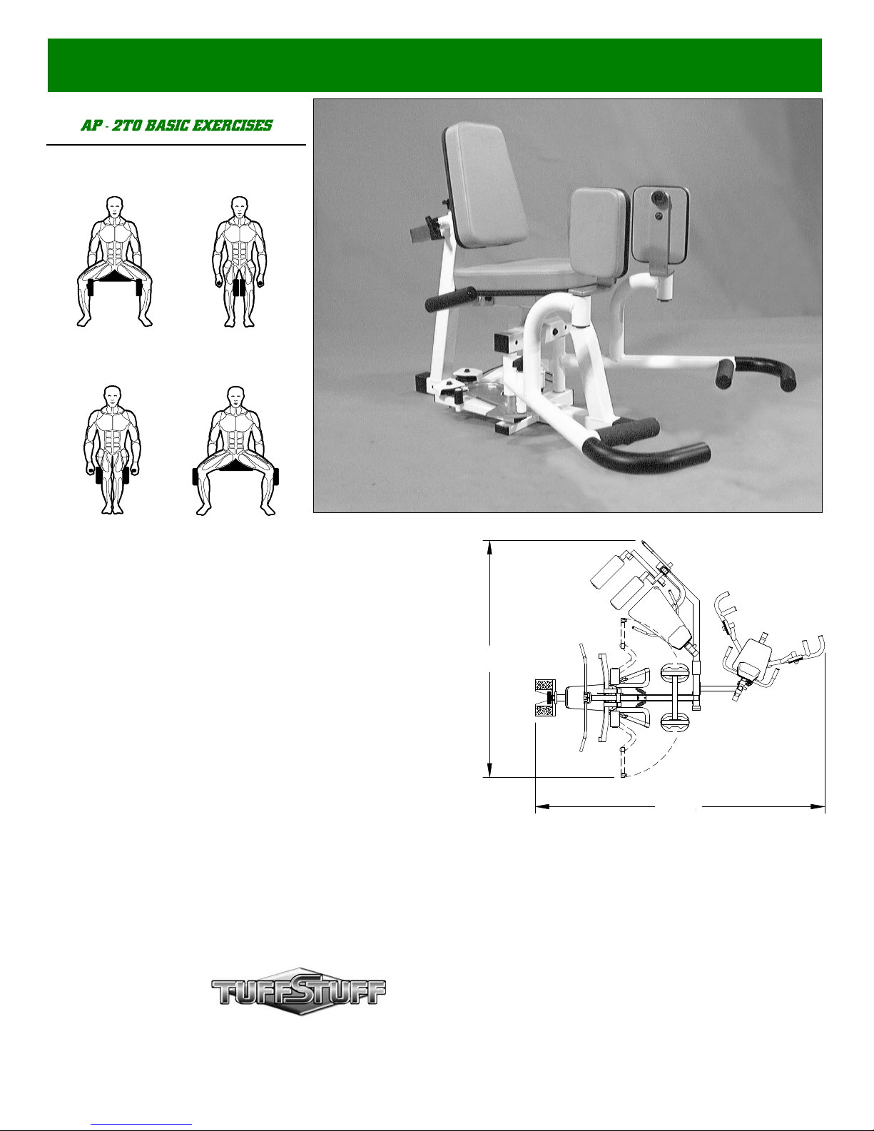
Start / End
Midpoint
INNER THIGH
OUTER THIGH
Revision Date 11-03-99
AP-2TO
Inner/ Outer Thigh (Option)
America’s Premium Exercise Equipment
100”
126”
L 126” W 100” H 83”
Page 2
Introduction
About the Inner / Outer (AP-2TO)
Congratulations on your new purchase of the Inner / Outer (AP2TO). We hope you are completely satisfied with this product and
wish you many years of enjoyment.
Tuff Stuff Equipment
Every Tuffstuff product has been built to precise quality
standards and has been carefully packaged to ensure that damage
will not occur during shipment.
signature indicating final inspection has been conducted by our line
foreman, is an expression of our confidence in the completeness,
the materials, and workmanship of this product.
The Home Lifetime Warranty and
Warranty
SEE WARRANTY REGISTRATION CARD
Registration Card
To avoid unnecessary delays in warranty service and to insure
that a permanent record of your purchase is on file with our factory,
be sure to complete the warranty registration card and send it to
Task Industries today.
Specifications
1. Maximum Wt. Capacity - 200 Lbs. Fixed on Apollo-250
2. Total Machine Weight - 60 Lbs.
3. Footprint (LWH) - See Front Cover
Maintenance Information
1. Lubrication of the Pivot Axles (#16) is essential to the longevity
and optimal performance of your Inner / Outer (AP-2TO). We
recommend multi-purpose grease for this application.
2. All cables and bushings should be checked regularly for signs of
wear.
3. Periodically check all moving parts, upholstery and grips for
wear. If replacement is necessary, please contact your local Tuff
Stuff retailer or call our Customer Service Department.
4. As needed, upholstery may be cleaned with a mild solution of
soap and water. Regular use of vinyl treatment will add to life
and appearance of your upholstery.
Tool Requirements
1.One 9/16” combination wrench
2.One 7/8” combination wrench
3.One 1/2” combination wrench
4.One ratchet
5.One 9/16” socket
6.One rubber mallet
7.External retaining-ring pliers
8.Multi-purpose grease
9.Measuring tape
10.Utility knife
Prior to the Assembly of the AP-2TO
1. We advise you to consult your local Tuff Stuff retailer if you
should have a question or problem regarding the proper
assembly of this Inner / Outer (AP-2TO).
2. Neatly organize and identify all parts according to the Parts List
on page 7 and the Exploded View Diagram on page 8.
S afety First
Regardless of how enthusiastic you may be about getting on your
equipment and exercising, take the time to ensure that your safety is
not jeopardized. A moment’s lack of attention can result in an accident,
as can failure to observe certain safety precautions.
1. Read, study and understand the Owner’s Manual and all the warning
labels on this product. Furthermore, it is recommended to familiarize
yourself and others with the proper operation and workout
recommendations for this Tuff Stuff product prior to use. Some of
this information can be obtained in this Owner’s Manual, as- well-as
from your local Tuff Stuff retailer.
2. It is imperative that you retain this Owner’s Manual and be sure all
warning labels are legible and intact. Replacement of Owner’s
Manual and labels are available from your local Tuff Stuff retailer.
3. Consult with your physician before beginning any exercise program.
4. Use proper discretion when children are present.
Safety Precautions
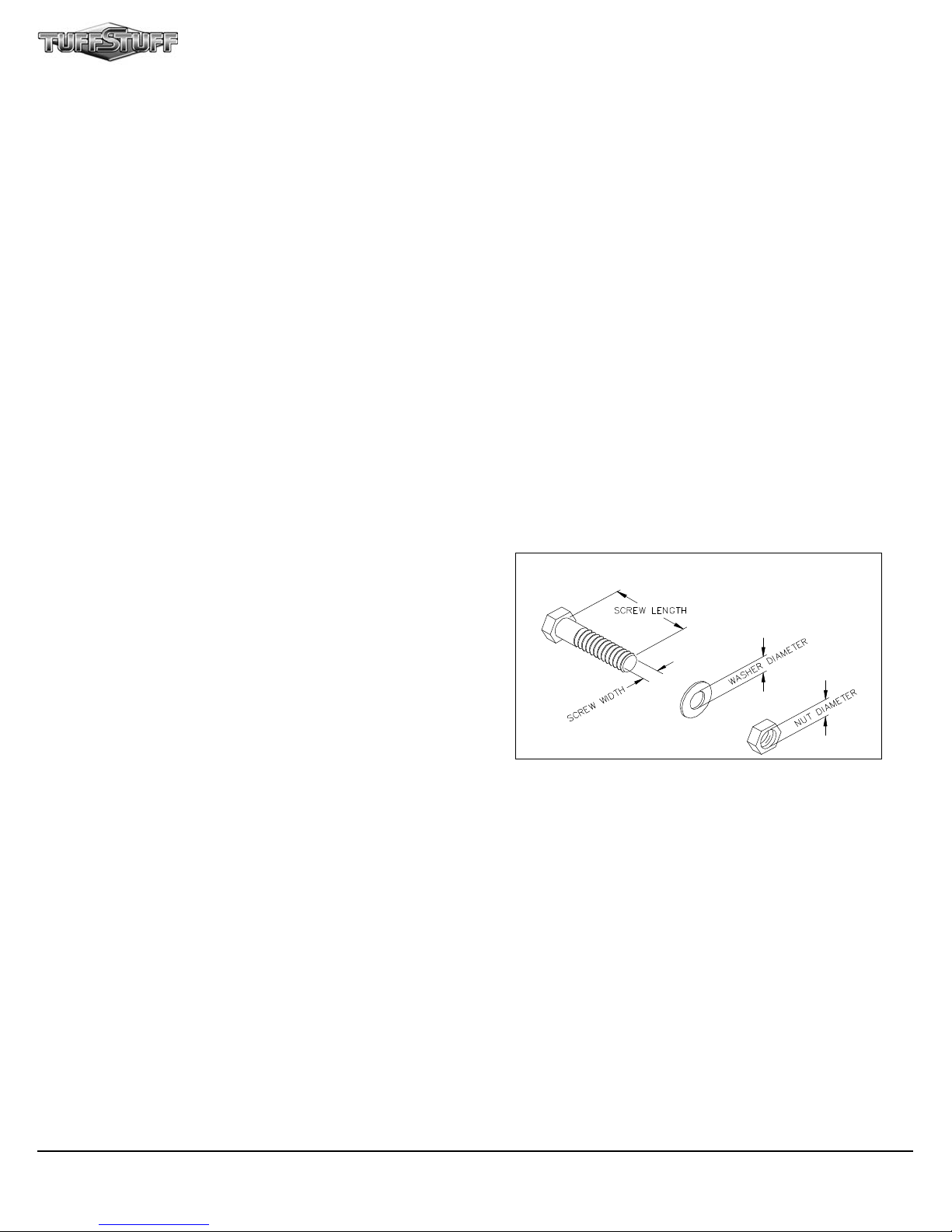
Hardware Measurement Diagram
5. Frayed or worn cables can be dangerous and may cause injury.
Periodically check these cables for any indication of wear.
6. Keep hands, limbs, loose clothing and long hair well out of the way
of moving parts.
7. Do not attempt to lift more weight than you can control safely.
8. Inspect the Inner / Outer (AP-2TO) for any sign of wear on parts,
hardware becoming loose or cracks on welds. If a problem is found,
do not use or allow the machine to be used until the defective part
is repaired or replaced.
9. Pay special attention to the Push Pull Pin 1/2 X 5 1/4 (#37) located
on the Right Leg Arm (#3). Be sure it is fully engaged into the
selectorized holes of the Adjustable Cam (#4).
Note: Due to continuing product improvements, specifications and designs are subject to change
without notice.
Even though we have prepared this manual with extreme care, neither the publisher nor the author
can accept responsibility for any errors in, or omission from, the information given.
1
AP-2TO Inner / Outer (Option)
Page 3
Owner’s Manual: Assembly Instructions
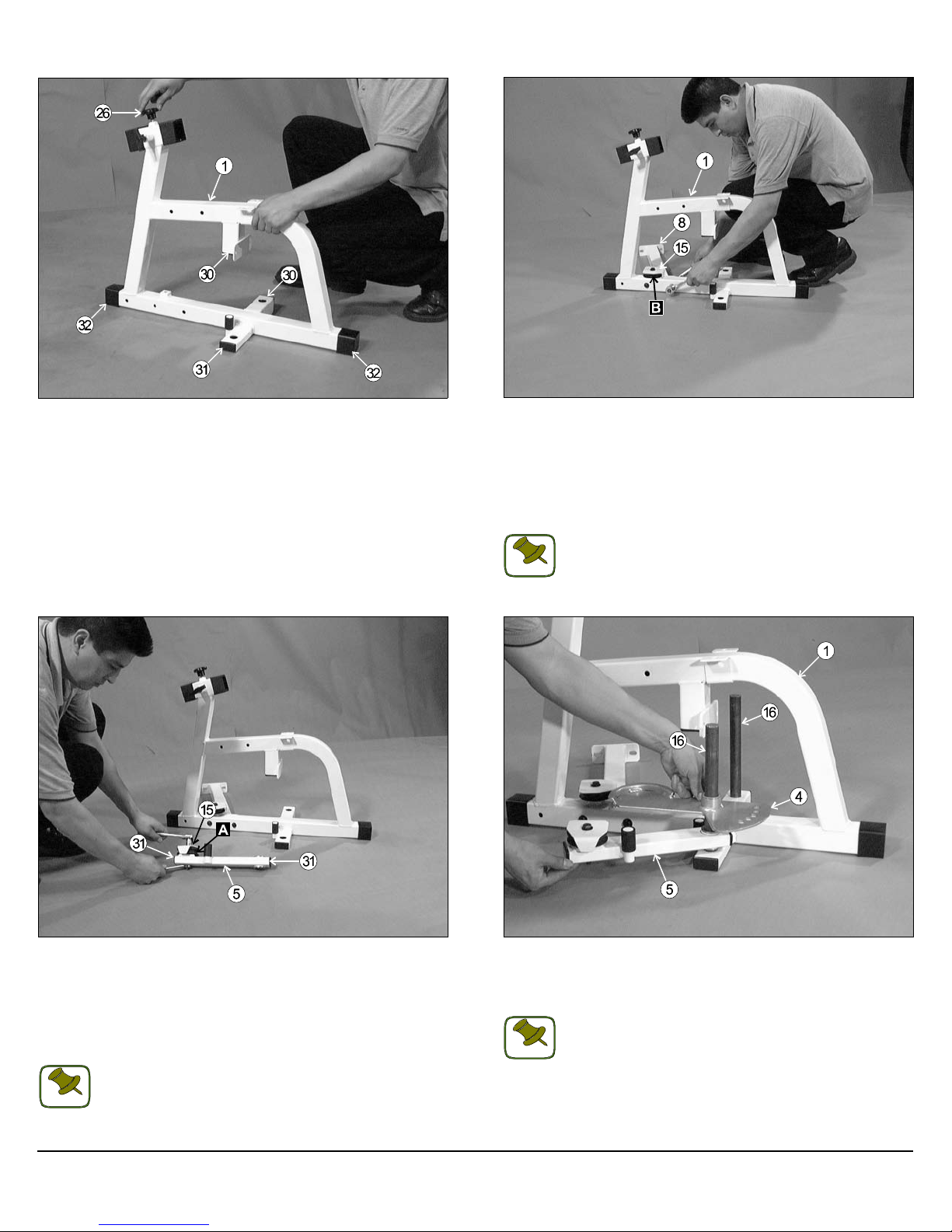
FIG. 1 Locate the Main Frame (#1) and, using a rubber mallet, insert
two Plastic Caps w/Groove 2 Sq. (#32) onto the tube-ends of the Main
Frame (#1), as labeled above. Next, insert two Plastic Insert Caps 2” Sq.
(#30) and one Plastic Insert Cap 1 X 2 (#31) into the tube-ends of the
Main Frame (#1), as labeled above. Then, thread a Plastic Knob 1/2 -13
X 1 (#26) into the thread socket located on the Main Frame (#1), as pictured above.
FIG. 2 Next, install one Nylon Pulley 3” Rd. (#14-Labeled B) and a
Small Cover Plate (#15), in the position shown above, to the Main
Frame (#1) and secure them into place using one Hex Head Cap Screw
3/8-16 X 1 1/2 (#40) and one Flat Washer SAE 3/8” (#46). Next, affix
the Connector Tube (#8) to the Main Frame (#1), as pictured above,
and secure it into place using two Hex Head Cap Screws 3/8-16 X 2 3/4
(#41), four Flat Washers SAE 3/8” (#46) and two Nylon Insert Jam Lock
Nuts 3/8-16 (#47).
Note: The black boxed letters pointing to the pulleys are used
throughout this manual as reference to the Cable Mapping
NOTE
Diagram on page 5. These black boxed letters will be primarily
used for locating certain pulleys during the assembly and the
cable routing process beginning with Fig. 16.
FIG. 3 Locate the Cam Support Tube (#5) and, using a rubber mallet,
insert two Plastic Insert Caps 1 x 2 (#31) into the tube-ends, as labeled
above. Next, install one Nylon Pulley 3” Rd. (#14-Labeled A) and a
Small Cover Plate (#15), in the position as shown above, to the Cam
Support Tube (#5) and secure them into place using one Hex Head
Cap Screws 3/8-16 X 2 3/4 (#41), two Flat Washers SAE 3/8” (#46) and
one Nylon Insert Jam Lock Nut 3/8-16 (#47).
Note: Be sure to position the Small Cover Plate (#15) as
shown in picture above.
NOTE
AP-2TO Inner / Outer (Option)
FIG. 4 Next, insert the two Pivot Axles (#16) into the receptacles on
the Main Frame (#1). Then, insert the Cam Support Tube (#5) and the
Adjustable Cam (#4), in the position as shown above, onto the left side
Pivot Axle (#16).
Note: It is recommended to grease the Pivot Axles (#16) with
multi-purpose grease prior to assembling. In addition, be sure
NOTE
to position the Cam Support Tube (#5) and the Adjustable
Cam (#4), as pictured above.
2
Page 4
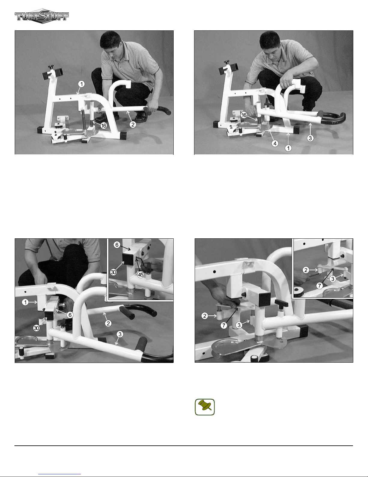
FIG. 5 Next, attach the Left Leg Arm (#2) onto the left side Pivot Axle
(#16), as pictured above.
FIG. 6 Next, attach the Right Leg Arm (#3) onto the right side Pivot
Axle (#16), as pictured above.
FIG. 7 Locate the Pivot Axle Support Tube (#6) and, using a rubber
mallet, insert two Plastic Insert Caps 2 Sq. (#30) into the tube-ends, as
labeled above. Next, maneuver the two Pivot Axles (#16) into the holes
on the bottom side of the Pivot Axle Support Tube (#6). Next, mount
the Pivot Axle Support Tube (#6) along with the two captive Pivot Ax-
les (#16) to the Main Frame (#1) and secure it into place using two Hex
Head Cap Screws 3/8-16 X 3 (#42), four Flat Washers SAE 3/8 (#46)
and two Nylon Insert Jam Lock Nuts 3/8-16 (#47). Then, secure the two
Pivot Axles (#16) to the Pivot Axle Support Tube (#6) using two Set
Screws 3/8-16 X 1/2 (#45). Use the supplied Hex Key 3/16” (#58) to secure the two Set Screws 3/8-16 X 1/2 (#45) into the threaded sockets on
the Pivot Axle Support Tube (#6), as shown in caption above.
3
FIG. 8 Connect the Left Leg Arm (#2) and the Right Leg Arm (#3) by
inserting the Pivot Actuator Plate (#7) into the receptacles on the Left
Leg Arm (#2) and the Right Leg Arm (#3), as shown above. Secure
this assembly using two Flat Washers SAE 3/8 (#46) and two Nylon Insert Lock Nuts 3/8-16 (#48), as shown in caption above.
Note: It is recommended to grease the axles on the Pivot
Actuator Plate (#7) with multi-purpose grease prior to
NOTE
assembling.
AP-2TO Inner / Outer (Option)
Page 5

FIG. 9 Next, attach the Right Handle (#9) and the Left Handle (#10)
to the Main Frame (#1) and secure them into place using two Hex Head
Cap Screws 3/8-16 X 3 (#42), four Flat Washers SAE 3/8 (#46) and two
Nylon Insert Jam Lock Nuts 3/8-16 (#47).
Owner’s Manual: Assembly Instructions
FIG. 10 Next, locate the Adjustable Back Pad Tube (#11) and insert
one Plastic Insert Cap 1 3/4 Sq. (#28) into the tube-end. Next, attach the
Adjustable Back Pad Tube (#11) to the Seat Pad (#12) and secure into
place using two Hex Head Cap Screws 3/8-16 X 1 1/4 (#38) and two Flat
Washers SAE 3/8 (#46). Next, insert the Adjustable Back Pad Tube
(#10) into the receptacle on the Main Frame (#1). Be sure to release
the Push-Pull Pin 1/2” (#25) as you begin to insert the assembled
Adjustable Back Pad Tube (#10) into the Main Frame (#1).
NOTE
Note: Be sure to position the Right Handle (#9) and the Left
Handle (#10), as pictured above.
Note: Be sure to attach the Adjustable Back Pad Tube (#11)
to the Seat Pad (#11) in the position as shown above.
NOTE
FIG. 11 Next, attach the Seat Pad (#13) to the Main Frame (#1) and
secure it into place using two Hex Head Cap Screws 3/8-16 X 1 1/4
(#38) and two Flat Washers SAE 3/8 (#46).
Note: Be sure to position the Seat Pad (#13) to the Main
Frame (#1) as pictured above. Refer to the Exploded View
NOTE
Diagram on page 7 for further clarification of this assembly.
AP-2TO Inner / Outer (Option)
FIG. 12 Insert the two Leg Pad Pivot Brackets (#17) to, both, the Left
Leg Arm (#2) and the Right Leg Arm (#3). Secure them both into place
using a Retaining Snap Ring (#19), as shown in caption above. Use a
external retaining-ring pliers for this job. If this tool is not available,
carefully work each Retaining Snap Ring (#19) into the groove, then
push-up alternately with a screw driver working the Retaining Snap Ring
(#34) into the groove of the Leg Pad Pivot Brackets (#17).
Note: Be careful not to distort the Retaining Snap Rings (#19)
or bend them.
NOTE
4
Page 6

FIG. 13 Next, attach the a Leg Pad (#18) to each of the Leg Pad
Pivot Brackets (#17). Secure the Leg Pad (#18), as shown in picture A
above, using two Button Head Screws 3/8-16 X 1 1/4 (#39) and two Flat
Washers SAE 3/8 (#46). Next, secure the other Leg Pad (#18), as
shown in picture B above, using one Button Head Screw 3/8-16 X 1 1/4
(#39) with one Flat Washer SAE 3/8 (#46) and, on top, one Hex Head
Cap Screw 3/8-16 X 1 1/2 (#40) and one Rubber Bumper 3/8 X 1 1/2
(#34). Refer to the Exploded View Diagram on page 9 for further clarification on this assembly.
Note: Position the Leg Pads (#18) to the Leg Pad Pivot
Brackets (#17), as shown above.
NOTE
Fig. 14 To attach the Inner / Outer Thigh to the Apollo-250 you must
first remove the bolt from the Apollo-250 (pointed with an arrow) and
also remove the Weight Shrouds from the Apollo-250 to allow the
attachment of the Inner / Outer Thigh and the routing of its cable.
Fig. 15 Next, attach the Inner / Outer Thigh to the Apollo-250 Rear
Upright and Base Frame, as pictured above, and secure it into place
using one Hex Head Cap Screws 3/8-16 X 4 1/4 (#43), one Hex Head
Cap Screws 3/8-16 X 4 (#44), four Flat Washers SAE 3/8 (#46) and two
Nylon Insert Lock Nuts 3/8-16 (#48).
5
FIG. 16 Next, insert and secure the AP-2TO Cable (#50) to the
bracket located on the Adjustable Cam (#4).
Note: Refer to Fig. B on page 9 for further illustration of this
Cable Routing.
NOTE
AP-2TO Inner / Outer (Option)
Page 7

Owner’s Manual: Assembly Instructions
FIG. 17 Next, route the AP-2TO Cable (#50) around the two Pulleys
3” Rd. (#14-Labeled A, B) as pictured above.
Note: Refer to the Cable Mapping Diagram on page 9 for further illustration of this Cable Routing.
NOTE
FIG. 18 Next, Remove the Leg Extension Tension Cable from the
pulley bracket on the Apollo-250 Base Frame, as illustrated on picture
above.
NOTE
Note: Refer to Cable Mapping Diagram on page 9 for further
clarification of this cable routing.
Fig. 19 Next, route the AP-2TO Cable (#50) in the Pulley Bracket,
Then, install a Nylon Pulley 4 1/2 Rd. (#51-Labeled C) on the pulley
bracket of the Apollo-250 Base Frame and secure it into place using
one Hex Head Cap Screw 3/8-16 X 1 3/4 (#49), two Flat Washers SAE
3/8 (#46) and one Nylon Insert Jam Lock Nut 3/8-16 (#47). Then, route
the AP-2TO Cable (#50) to the Apollo-250 Adjustable Double Pulley
Plates. Then, remove the existing pulley and attach the AP-2TO Cable
(#50) using the hardware illustrated in Fig. A on the back page.
Fully Fasten: It is highly recommended that you double check
and fully fasten all hardware assemblies and inspect the cable
routing.
AP-2TO Inner / Outer (Option)
6
Page 8

AP-2TO PARTS LIST
COLOR CHART
COLOR CHART
GRAY= SUB-ASSEMBLY PARTS
GRAY= SUB-ASSEMBLY PARTS
BLACK= HARDWARE
BLACK= HARDWARE
Item Description Part No. Qty Item Description Part No. Qty
1 MAIN FRAME UP351 1 30 PLASTIC INSERT CAP 2" SQ BNH0012 4
2 LEFT LEG ARM UP352 1 31 PLASTIC INSERT CAP 1 X 2 BNH0005 3
3 RIGHT LEG ARM UP353 1 32 PLASTIC END CAP W/GROOVE 2" SQ. BNH0051 2
4 ADJUSTABLE CAM UP354 1
5 CAM SUPPORT TUBE UP355 1
6 PIVOT AXLE SUPPORT TUBE UP356 1
7 PIVOT ACTUATOR PLATE UP357 1
8 CONNECTOR TUBE UP358 1 37 PUSH-PULL PIN 1/2" X 5 1/4" BNH0586 1
9 RIGHT HANDLE UP359 1 38 HEX HEAD CAP SCREW 3/8-16 X 1 1/4 BNH0273 4
10 LEFT HANDLE UP360 1 39 BTTN HEAD CAP SCREW 3/8-16 X 1 1/4 BNH0879 3
11 ADJUSTABLE BACK PAD TUBE UP361 1
12 BACK PAD UP158 1
13 SEAT PAD UP188 1
14
NYLON PULLEY 3" RD BNH0553 2 43 HEX HEAD CAP SCREW 3/8-16 X 4 1/4 BNH0317 1
15 SMALL COVER PLATE UP362 2 44 HEX HEAD CAP SCREW 3/8-16 X 4 BNH0285 1
16 PIVOT AXLE 1 X 10 13/16 UP363 2 45 SET SCREW 3/8-16 X 1/2 BNH0474 4
17 LEG PAD PIVOT BRACKET UP364 2 46 FLAT WASHER SAE 3/8" BNH0239 30
LEG PAD UP365 2
18
19 RETAINING SNAP RING BNH0419 2 48 NYLON INSERT LOCK NUT 3/8-16 BNH0214 4
20 NYLON BUSHING 1 X 1 1/2 BNH0531 4 49 HEX HEAD CAP SCREW 3/8-16 X 1 3/4 BNH0274 1
21 BRONZE BUSHING 1 X 1 1/4 BNH0527 8 50
22 BRONZE BUSHING 1/2 X 5/8 BNH0528 4 51 NYLON PULLEY 4 1/2 RD BNH0556 1
23 RUBBER GRIP 1 1/4 X 6 BNH0937 2 52 NYLON SPACER 3/8 X 3/8 BNH0392 2
24 PLASTIC INSERT CAP 1 1/4" RD BNH0573 2 53 BTTN HEAD CAP SCREW 3/8-16 X 1 1/2 BNH0109 1
25 TURN/PULL PIN W/KNOB BNH0929 1 54 HEX KEY 7/32" BNH0575 1
27 PLASTIC TUBE GUIDE W/LIP 2 1/4" SQ. BNH0059 2 55 HEX KEY 3/16" BNH0371 1
28 PLASTIC INSERT CAP 13/4" SQ BNH0053 1 56 DECAL-EXERCUISE INNER/OUTER THIGHT BNH0230 1
29 PLASTIC INSERT CAP 1 3/4 RD. BNH0011 4
33 UHMW STOPPER 1/2 X 1 X 1 3/8 BNH0198 2
34 RUBBER BUMPER 3/8 X 1 1/2 BNH0514 1
35 RUBBER TUBE 1 7/8 X 6 BNH0978 2
36 RUBBER TUBE 1 7/8 X 13 BNH0980 2
40 HEX HEAD CAP SCREW 3/8-16 X 1 1/2 BNH0303 1
41 HEX HEAD CAP SCREW 3/8-16 X 2 3/4 BNH0278 3
42 HEX HEAD CAP SCREW 3/8-16 X 3 BNH0282 4
47 NYLON INSERT JAM LOCK NUT 3/8-16 BNH0365 9
AP-2TO CABLE AP2TO-50-00 1
7
AP-2TO Inner / Outer (Option)
Page 9

AP-2TO EXPLODED VIEW DIAGRAM
AP-2TO Inner / Outer (Option)
8
Page 10

AP-2TO CABLE MAPPING DIAGRAM
9
AP-2TO Inner / Outer (Option)
Page 11

NOTES
AP-2TO Inner / Outer (Option)
10
Page 12

DO NOT DISCARD THIS MANUAL
HOME LIFETIME WARRANTY
TuffStuff products are warranted to the retail purchaser to be free from defects in materials and workmanship.
TuffStuff exclusive Home Lifetime Warranty coverage extends for the life of the product while owned by the
original retail purchaser, and used only in a home or residential setting unless otherwise noted in the owner’s
manual.
This warranty does not cover:
1. TuffStuff products sold for and used in a commercial or institutional setting.
2. Any damage, failure or loss caused by accident, misuse, neglect, abuse, improper assembly, improper
maintenance, or failure to follow instructions or warnings in the owner’s manual and warning labels
posted on the machine.
3. Use of products in a manner for which they were not designed.
4. Original product that is altered, or the use of replacement parts and components of another manufacturer other than TuffStuff.
Limitations:
The foregoing shall constitute the sole remedy of the purchaser and the sole liability of TuffStuff with regard to
warranty, whether express or implied by operation of law or otherwise, including but not limited to any implied
warranties of merchantability or fitness. TuffStuff shall in no event be liable for incidental or consequential
losses, damages or expenses in connection with exercise products. TuffStuff’s liability hereunder is expressly
limited to the repairs or replacements of warranted defective parts.
Procedures:
Warranty service will be performed at TuffStuff’s facility in Pomona, California. TuffStuff will have the option of
either repair or replacement at no charge for any defective product. Purchaser is responsible for installation of
repaired or replaced parts and all transportation and insurance costs on returned or replaced equipment to and
from TuffStuff’s facility in Pomona.
This warranty gives you specific legal rights and you may also have other rights, which may vary from state to
state. Effective July 1, 2004.
This warranty is the final, complete and exclusive agreement of the parties with respect to the quality or performance of the equipment
and no action for breach of this written warranty or any implied warranty shall be commenced more than one (1) year after the accrual
of the cause of action. No modification of this warranty or waiver of its terms shall be binding on either party unless approved in
writing by an authorized representative of the party. Contact TuffStuff at 1325 E. Franklin Avenue, Pomona, California 91766, before
returning any defective equipment.
Note: Retain your sales receipt and be sure to mail in the warranty registration card to insure that a
permanent record of your purchase is on file with the factory and to avoid unnecessary delays in
warranty service.
TASK INDUSTRIES, INC.
1325 E. Franklin Ave., Pomona, CA 91766
Ph: 909-629-1600 Fax: 909-629-4967
E-mail: service@tuffstuff.net Net: www.tuffstuff.net
 Loading...