

Page 1
ASSEMBLY INSTRUCTIONS
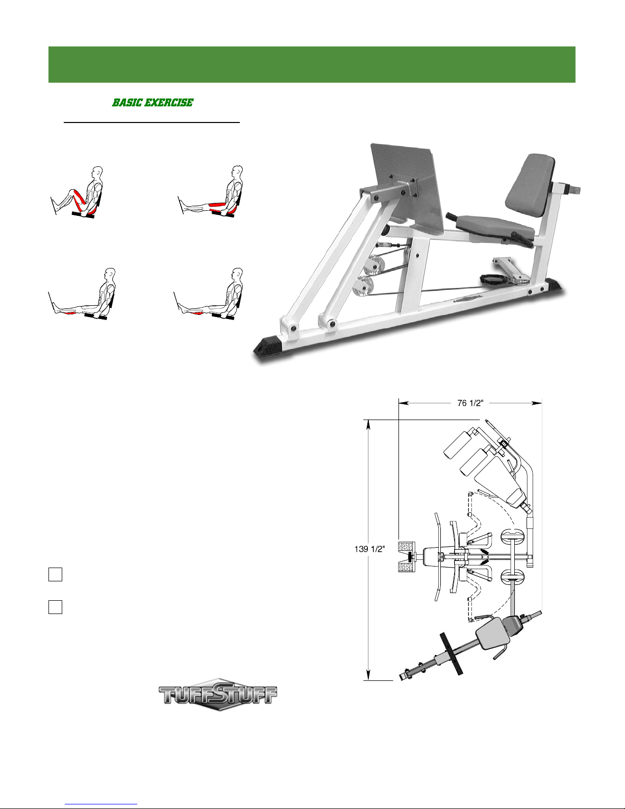
Start / End
Midpoint
LEG PRESS
CALF RAISE
Revision Date 04-21-03
Leg Press Option,
Double Fulcrum
Includes Assembly for:
AP-2LPS
Standard
AP-2LPD
Deluxe
America’s Premium Exercise Equipment
© 2003 TASK INDUSTRIES, INC.
L 76 1/2” W 139 1/2” H 83”
AP-2LPS_AP-2LPD Rev0
Page 2
About the Leg Press Option
Congratulations on your new purchase of the Leg Press Option.
We hope you are completely satisfi ed with this product and wish
you many years of enjoyment.
Prior to the Assembly of the Leg Press Option
1. We advise you to consult your local Tuff Stuff retailer if you
should have a question or problem regarding the proper
assembly of this unit.
Tuff Stuff Equipment
This Tuffstuff product has been built to precise quality standards
and has been carefully packaged to ensure that damage will
not occur during shipment. The Home Lifetime Warranty and
signature indicating fi nal inspection has been conducted by our line
foreman, is an expression of our confi dence in the completeness,
the materials, and workmanship of this product.
Warranty
SEE A COPY OF WARRANTY ON BACK PAGE.
Registration Card
To avoid unnecessary delays in warranty service and to insure that
a permanent record of your purchase is on fi le with our factory, be
sure to complete the warranty registration card and send it to Task
Industries today.
Specifi cations
1. Maximum Wt. Capacity - 200 Lbs. Fixed
2. Total Machine Weight - 150 Lbs.
3. Footprint (LWH) - See Front Cover.
Note: Due to continuing product improvements, specifi cations and designs are subject to change
without notice.
2. Neatly organize and identify all parts according to the Parts List
on page 7 and the Exploded View Diagram on page 8.
Tool Requirements
1. One 9/16” combination wrench
2. One 1/2” combination wrench
3. One ratchet
4. One 9/16” socket
5. One 1/2” socket
6. One rubber mallet
7. Windex or household glass cleaner
8. Measuring tape
9. Utility knife
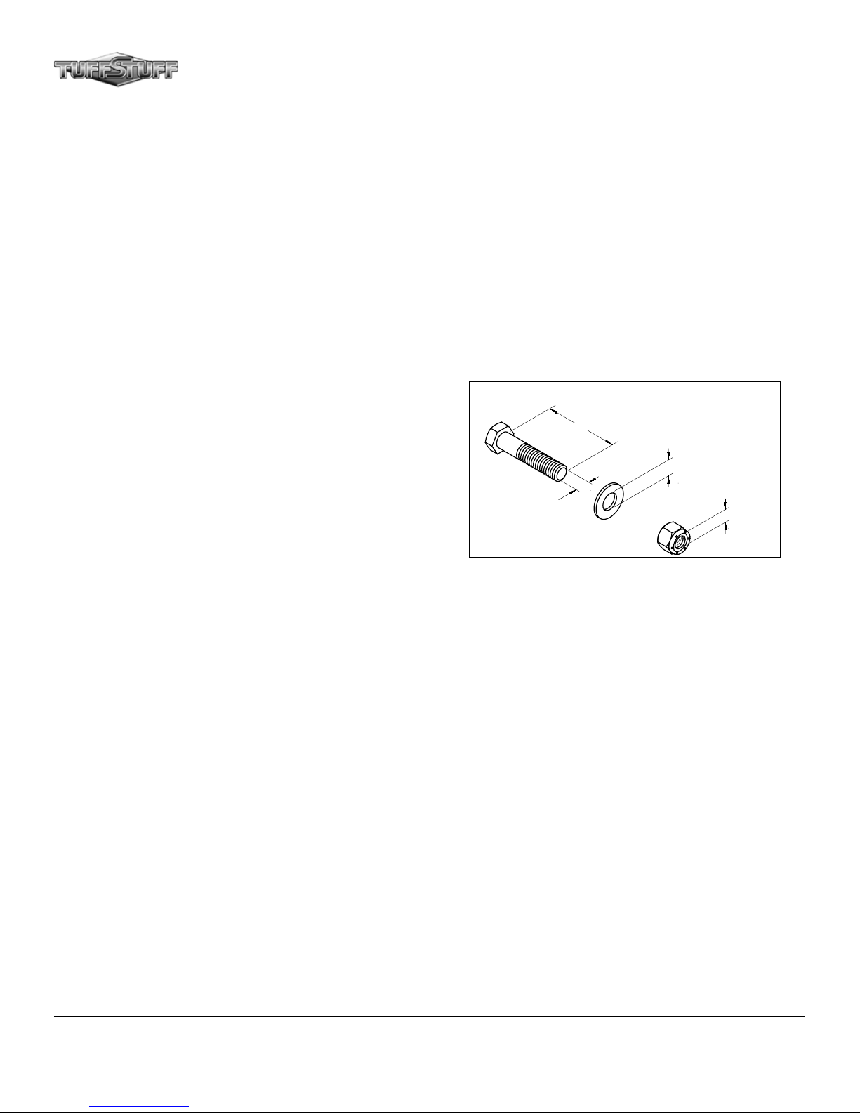
Hardware Measurement Diagram
SCREWfiLENGHT
WASHERfiDIAMETER
SCREWfiWIDTH
NUTfiDIAMETER
Safety Precautions
Safety First
Regardless of how enthusiastic you may be about getting on
your equipment and exercising, take the time to ensure that your
safety is not jeopardized. A moment’s lack of attention can result
in an accident, as can failure to observe certain simple safety
precautions.
1. Read, study and understand the Assembly Instructions and all the
warning labels on this product. Furthermore, it is recommended
to familiarize yourself and others with the proper operation and
workout recommendations for this Tuff Stuff product prior to
use. Some of this information can be obtained in this Assembly
Instructions, as-well-as from your local Tuff Stuff retailer.
2. It is imperative that you retain this Assembly Instructions and
be sure all warning labels are legible and intact. Replacement
Assembly Instructions and labels are available from your local
Tuff Stuff retailer.
3. Consult with your physician before beginning any exercise
program.
4. Use proper discretion when children are present.
5. Frayed or worn cables can be dangerous and may cause injury.
Periodically check these cables for any indication of wear.
6. Keep hands, limbs, loose clothing and long hair well out of the
way of moving parts.
7. Do not attempt to lift more weight than you can control safely.
8. Inspect the Unit for any sign of wear on parts, hardware
becoming loose or cracks on welds. If a problem is found do
not use or allow the machine to be used until the defective
part is repaired or replaced.
1
AP-2LPS_AP-2LPD Leg Press Option
Page 3
Assembly Instructions
44
2
40
1
40
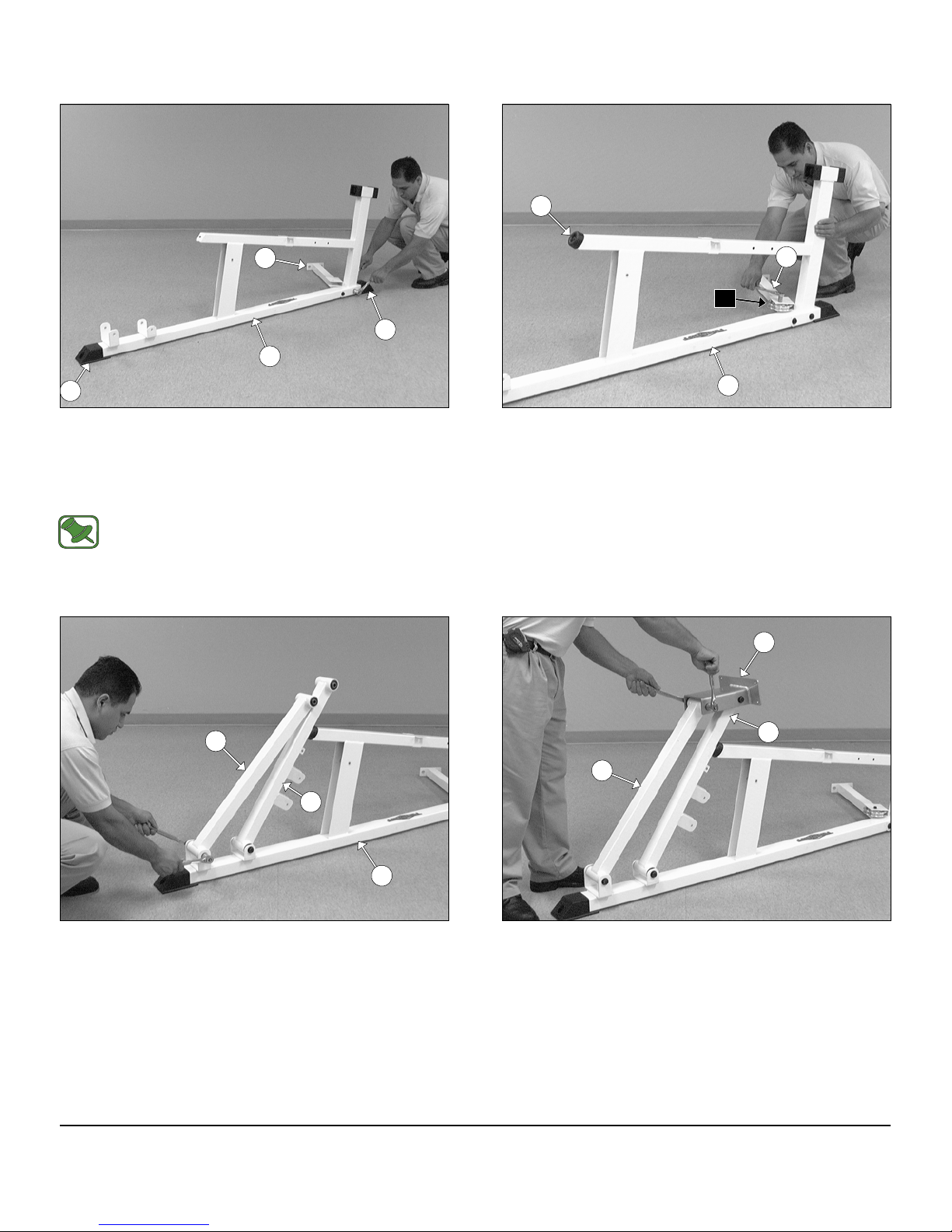
FIG. 1 Using a rubber mallet, insert two Plastic End Caps 2 X 3
(#40) onto the tube-ends of the Main Frame (#1). Next, attach the
Stabilizer Support (#2) to the Main Frame (#1), in the position shown
above, and secure it into place using two Hex Head Cap Screws 1/213 X 4 1/4 (#31), four Flat Washers SAE 1/2” (#24) and two Nylon
Insert Jam Lock Nuts 1/2-13 (#37).
Note: Refer to the Exploded View Diagram on page 8 for
further clarifi cation of this assembly.
2
G5
1
FIG. 2 Insert a Pulley 3/8 X 4 1/2 (#15-Labeled G5) into the pulley
bracket of the Stabilizer Support (#2) and secure it into place using
one Hex Head Cap Screw 3/8-16 X 1 3/4 (#28) and one Split Lock
Washer 3/8” (#46). Next attach a Rubber Bumper 3/8 X 2 1/2 (#44) to
the Main Frame (#1) and secure it into place using one Hex Head Cap
Screw 3/8-16 X 1 1/2 (#26) and one Steel Bumper Washer 3/8” (#48).
5
3
4
1
FIG. 3 Next, affi x the Fulcrum (#3) to the bracket of the Main
Frame (#1) and secure it into place using one Hex Head Cap Screw
1/2-13 X 5 1/2 (#32), two Flat Washers SAE 1/2” (#24) and one Nylon
Insert Jam Lock Nut 1/2-13 (#39). Next, affi x the Fulcrum w/Brackets
(#4) to the bracket of the Main Frame (#1), in the position as shown
above, and secure it into place using one Hex Head Cap Screw 1/2-13
X 5 1/2 (#32), two Flat Washers SAE 1/2” (#24) and one Nylon Insert
Jam Lock Nut 1/2-13 (#39).
AP-2LPS_AP-2LPD Leg Press Option
4
3
FIG. 4 Attach the Foot Plate Bracket (#5) to, both, the Fulcrum
(#3) and the Fulcrum w/Brackets (#4) in the position shown above,
and secure it into place using two Hex Head Cap Screws 1/2-13 X 5
1/2 (#32), four Flat Washers SAE 1/2” (#24) and two Nylon Insert Jam
Lock Nuts 1/2-13 (#39).
2
Page 4

4
G1
G3
1
G2
G4
FIG. 5 Attach two Pulleys 3/8 X 4 1/2 (#15-Labeled G4, G2) to the
pulley brackets of the Fulcrum w/Brackets (#4) and secure them into
place using two Hex Head Cap Screws 3/8-16 X 1 3/4 (#28), four Flat
Washers SAE 3/8” (#25) and two Nylon Insert Jam Lock Nuts 3/8-16
(#37). Next, attach two Pulleys 3/8 X 4 1/2 (#15-Labeled G1, G3) inside the channel of the Main Frame (#1) and secure them into place
using one Hex Head Cap Screw 3/8-16 X 2 3/4 (#29), two Flat Washers SAE 3/8” (#25) and one Nylon Insert Jam Lock Nut 3/8-16 (#37).
1
9
10
FIG. 6 Next, attach the Handle RT (#9) and the Handle LT (#10)
to the Main Frame (#1), in the position as shown above, and secure
them into place using two Hex Head Cap Screws 3/8-16 X 3 1/4 (#30),
two Flat Washers SAE 3/8” (#25) and two Nylon Insert Lock Nuts 3/816 (#38).
41
11
1
FIG. 7 Affi x the Seat Pad (#11) to the bracket of the Main Frame
(#1), in the position shown above, and secure it using two Hex Head
Cap Screws 3/8-16 X 1 1/4 (#27) and two Flat Washers SAE 3/8”
(#25). Next, secure the other end of the Seat Pad (#11), as Illustrated
with arrow above, to the Main Frame (#1) using one Hex Head Cap
Screw 3/8-16 X 3 (#33) and one Flat Washer SAE 3/8” (#25).
3
7
12
FIG. 8 Locate the Adjustable Back Pad Tube (#7) and, using a
rubber mallet, insert one Plastic Insert Cap 1 3/4 Sq. (#41) into the
tube-end. Next, attach the Adjustable Back Pad Tube (#7) to the
Back Pad (#12), in the position shown above, and secure it into place
using two Hex Head Cap Screws 3/8-16 X 1 1/4 (#27) and two Flat
Washers SAE 3/8” (#25).
AP-2LPS_AP-2LPD Leg Press Option
Page 5

Assembly Instructions
12
207
1
FIG. 9 Disengage the Turn/Pull Pin w/Knob (#20). Then, insert
the Adjustable Back Pad Tube (#7) into the receptacle of the Main
Frame (#1).
8
47
21
36
13
FIG. 10 Locate the Leg Press Cable (#13) and thread one Finished
Hex Nut 1/2-13 (#21) onto the Cable Hex Tap Bolt 1/2-13 X 3 (#36),
as shown above. Next, insert one Split Lock Washer 1/2” (#47) and
thread the Swivel Cable End (#8) onto the Cable Hex Tap Bolt 1/2-13
X 3 (#36).
4
8
13
FIG. 11 Affi x the Swivel Cable End (#8) to the Fulcrum w/Brackets
(#4) and secure it into place using one Hex Head Cap Screw 3/8-16
X 1 3/4 (#28), two Flat Washers SAE 3/8” (#25) and one Nylon Insert
Jam Lock Nut 3/8-16 (#37).
Note: Refer to Fig. A of the Cable Mapping Diagram on page
6 for further clarifi cation of this assembly.
AP-2LPS_AP-2LPD Leg Press Option
G1
4
G3
G2
1
13
FIG. 12 Route the Leg Press Cable (#13) across and over the
Pulley 3/8 X 4 1/2 (#15-Labeled G1) on the Main Frame (#1), then
across and over the Pulley 3/8 X 4 1/2 (#15-Labeled G2) on the
Fulcrum w/Brackets (#4).
Note: Refer to the Cable Mapping Diagram on page 6 for
further detailed illustration of the Leg Press Cable (#13)
Routing.
4
Page 6

4
G3
G4
1
13
G4
2
G5
1
FIG. 13 Continue routing the Leg Press Cable (#13) across and
over the Pulley 3/8 X 4 1/2 (#15-Labeled G3) on the Main Frame (#1),
then around the Pulley 3/8 X 4 1/2 (#15-Labeled G4) on the Fulcrum
w/Brackets (#4).
Note: Refer to the Cable Mapping Diagram on page 6 for
further detailed illustration of the Leg Press Cable (#13)
Routing.
5
6
FIG. 14 Continue routing the Leg Press Cable (#13) through the
channel of the Main Frame (#1), then around the Pulley 3/8 X 4 1/2
(#15-Labeled G5) on the Main Frame (#1).
Note: Refer to the Cable Mapping Diagram on page 6 for
further detailed illustration of the Leg Press Cable (#13)
Routing.
33
25
38
25
2
33
AP-250S/AP-250D
Base Frame
25
FIG. 15 Attach the Foot Plate (#6), in the position shown above, to
the Foot Plate Bracket (#5) and secure it into place using four Flat
Head Socket Cap Screws 3/8-16 X 1 1/4 (#22), four Flat Washers SAE
3/8” (25) and four Nylon Insert Lock Nuts 3/8-16 (#38).
5
FIG. 16 Attach the Stabilizer Support (#2) to the AP-250S/AP250D Base Frame using two Hex Head Cap Screws 3/8-16 X 3 (#33),
four Flat Washers SAE 3/8” (#25) and two Nylon Insert Lock Nuts 3/816 (#38).
Next, continue routing the Leg Press Cable (#13) to the AP-250S or
AP-250D using the Cable Mapping Diagram on page 6 and secure into
place using the hardware as illustrated in Fig. B.
Note: The item numbers corresponding to the hardware
illustrated in Fig B on page 6 should be referenced on your
AP-250S or AP-250D Parts List.
AP-2LPS_AP-2LPD Leg Press Option
Page 7

G1
Assembly Instructions
13
G3
36
Some parts have
8
G2
G4
FIG. C
been cut away for clarity.
Note:
G7
13
G9
102
13
117
118
AP-2LPS_AP-2LPD CABLE MAPPING DIAGRAM
to the hardware illustrated in Fig. B
below should be referenced on your AP-
250S or AP-250D Parts List.
Note: The item numbers corresponding
G6
FIG. B
G8
G1
G5
G3
G2
G4
13
36
21
47
8
FIG. A
AP-2LPS_AP-2LPD Leg Press Option
6
Page 8

A
P-2LPS
A
Parts List
1 MAIN FRAME UP2247 125FLAT WASHER SAE 3/8" BNH0239 27
2 STABILIZER SUPPORT UP2248 126HEX HEAD CAP SCREW GR-5 B/O 3/8-16 X 1 1/2 BNH0303 1
3 FULCRUM UP2019 127HEX HEAD CAP SCREW GR-5 B/O 3/8-16 X 1 1/4 BNH0273 4
4 FULCRUM WITH BRACKETS UP2020 128HEX HEAD CAP SCREW GR-5 B/O 3/8-16 X 1 3/4 BNH0274 5
COLOR CHART
GRAY= SUB-ASSEMBLY PARTS
Item No. Description Part No. Qty Item No. Description Part No. Qty
BLACK= HARDWARE
P-2LPD
Parts List
All parts same as AP-2LPS, except for the part listed below
Description Part No. Qty
8 SWIVEL CABLE END UP2032 132HEX HEAD CAP SCREW GR-5 B/O 1/2-13 X 5 1/2 BNH0267 4
5 FOOT PLATE BRACKET UP2018 129HEX HEAD CAP SCREW GR-5 B/O 3/8-16 X 2 3/4 BNH0278 1
6 FOOT PLATE UP2251 130HEX HEAD CAP SCREW GR-5 B/O 3/8-16 X 3 1/4 BNH0312 2
9 HANDLE (RT) UP0270 133HEX HEAD CAP SCREW GR-5 B/O 3/8-16 X 3 BNH0282 3
7 ADJUSTABLE BACK PAD TUBE UP2015 131HEX HEAD CAP SCREW GR-5 B/O 1/2-13 X 4 1/4 BNH0291 2
10 HANDLE (LT) UP0271 134HEX KEY 7/32 BNH0575 1
11 SEAT PAD UP0146 135HEX KEY 3/32" BNH0372 1
12 BACK PAD UP0145 136CABLE HEX TAP BOLT Z/P 1/2-13 X 3 BNH1048 1
13 LEG PRESS CABLE UP2250 137NYLON INSERT JAM LOCK NUT 3/8-16 BNH0365 5
14 BEARING SPACER UP2308 438NYLON INSERT LOCK NUT 3/8-16 BNH0214 8
15 NYLON PULLEY 4 1/2 RD. BNH0556 6 39 NYLON INSERT JAM LOCK NUT B/O 1/2-13 BNH0366 6
16 BEARING 6203 W/1/2 BUSHINGS BNH0835 8 40 PLASTIC END CAP 2 X 3 BNH0606 2
17 BRONZE BUSHING 3/8 X 1/2 X 5/16 BNH0737 2 41 PLASTIC INSERT CAP 1 3/4" SQ. BNH0053 1
18 DECAL-ADJUST CABLE HERE BNH0789 1 42 PLASTIC INSERT CAP 1" RD. 10-12 GA. BNH0002 2
19 DECAL-LARGE TUFFSTUFF BNH0360 1 43 PLASTIC TUBE GUIDE W/LIP-TEETH 2 1/4" SQ. BNH0059 2
20 TURN/PULL PIN W/KNOB AND LOCK BNH0989 1 44 RUBBER BUMPER 3/8 X 2 1/2 BNH0511 1
21 FINISHED HEX NUT B/O 1/2-13 BNH0201 1 45 RUBBER GRIP 1 ID X .125 X 7 1/2 BNH0965 2
22 FLAT HEAD SOCKET CAP SCREW B/O 3/8-16 X 1 1/4 BNH0667 4 46 SPLIT LOCK WASHER B/O 3/8" BNH0658 1
23 FLAT PHILLIPS MACHINE SCREW 8-32 X 1/4 BNH0408 1 47 SPLIT LOCK WASHER Z/P 1/2" BNH0572 1
24 FLAT WASHER SAE 1/2" BNH0238 12 48 STEEL BUMPER WASHER Z/P 3/8" BNH0498 1
15 ALUMINUM PULLEY 3/8" X 4 1/2" BNH0069 6
Item No.
7
AP-2LPS_AP-2LPD Leg Press Option
Page 9

43
41
7
27
25
27
25
43
23
20
40
10
25
31
24
Assembly Instructions
25 30
4542
9
12
11
24
39
46
28
33
25
28
25
15
25
AP-2LPS_AP-2LPD EXPLODED VIEW
37
38
2
33
22
22
25
39
38
25
24
38
6
15
25
1
16
14
4
25
25
16
26
33
25
44
27
48
32
17
8
17
25
37
25
25
15
28
25
15
39
29
39
28
25
24
24
25
32
24
40
15
16
BASE FRAME
AP-250S/AP-250D
AP-2LPS_AP-2LPD Leg Press Option
25
38
39
5
24
38
24
37
16
16
25
37
16
14
16
14
3
14
16
8
Page 10

DO NOT DISCARD THIS MANUAL
HOME LIFETIME WARRANTY
TuffStuff products are warranted to the retail purchaser to be free from defects in materials and workmanship.
TuffStuff exclusive Home Lifetime Warranty coverage extends for the life of the product while owned by the
original retail purchaser, and used only in a home or residential setting unless otherwise noted in the owner’s
manual.
This warranty does not cover:
1. TuffStuff products sold for and used in a commercial or institutional setting.
2. Any damage, failure or loss caused by accident, misuse, neglect, abuse, improper assembly, improper
maintenance, or failure to follow instructions or warnings in the owner’s manual and warning labels
posted on the machine.
3. Use of products in a manner for which they were not designed.
4. Original product that is altered, or the use of replacement parts and components of another manufacturer other than TuffStuff.
Limitations:
The foregoing shall constitute the sole remedy of the purchaser and the sole liability of TuffStuff with regard to
warranty, whether express or implied by operation of law or otherwise, including but not limited to any implied
warranties of merchantability or fitness. TuffStuff shall in no event be liable for incidental or consequential
losses, damages or expenses in connection with exercise products. TuffStuff’s liability hereunder is expressly
limited to the repairs or replacements of warranted defective parts.
Procedures:
Warranty service will be performed at TuffStuff’s facility in Pomona, California. TuffStuff will have the option of
either repair or replacement at no charge for any defective product. Purchaser is responsible for installation of
repaired or replaced parts and all transportation and insurance costs on returned or replaced equipment to and
from TuffStuff’s facility in Pomona.
This warranty gives you specific legal rights and you may also have other rights, which may vary from state to
state. Effective July 1, 2004.
This warranty is the final, complete and exclusive agreement of the parties with respect to the quality or performance of the equipment
and no action for breach of this written warranty or any implied warranty shall be commenced more than one (1) year after the accrual
of the cause of action. No modification of this warranty or waiver of its terms shall be binding on either party unless approved in
writing by an authorized representative of the party. Contact TuffStuff at 1325 E. Franklin Avenue, Pomona, California 91766, before
returning any defective equipment.
Note: Retain your sales receipt and be sure to mail in the warranty registration card to insure that a
permanent record of your purchase is on file with the factory and to avoid unnecessary delays in
warranty service.
TASK INDUSTRIES, INC.
1325 E. Franklin Ave., Pomona, CA 91766
Ph: 909-629-1600 Fax: 909-629-4967
E-mail: service@tuffstuff.net Net: www.tuffstuff.net
 Loading...