

Page 1
OWNER’S MANUAL
TABLE OF CONTENTS:
Introduction - Pg. 1
Safety Precautions - Pg. 2
Assembly for AP-250S_AP-250D
Pg. 3 - Pg.23
Cable Adjustments - Pg. 22
Cable Mapping Diagrams
Pg. 24 - Pg. 29
Parts List - Pg. 31
Exploded View Diagram
Fold-Out Pg. 32
Adjustment Features
Pg. 33 - Pg. 36
Maintenance - Pg. 37
Optional Stations - Pg. 38 - Pg. 39
Warranty - Back Page
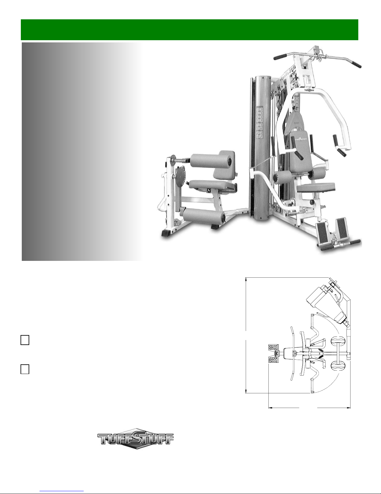
Apollo 2-Stack Gym System
Includes Assembly for:
AP-250S
Apollo 2-Stack Gym System (Standard)
AP-250D
Apollo 2-Stack Gym System (Deluxe)
Revision Date 06-12-03
100”
America’s Premium Exercise Equipment
72”
L 72” W 100” H 83”
Page 2
Int
roduction
i
e
v
e
n
i
e
o
g
o
y
-
r
t
y
y
t
y
m
bout the AP-250S_AP-250D
ongratulations on your new purchase of the AP-250S_AP-250D.
his gym is capable of a variety of different exercises, as well as,
mooth and user-friendly adjustment features. In addition, this gym
as been designed to meet the needs and performance
quirements for a suitable home exercise machine. We hope you
re completely satisfied with this product and wish you many years
f enjoyment.
uff Stuff Equipment
his Tuffstuff product has been built to precise quality standards
nd has been carefully packaged to ensure that damage will not
ccur during shipment.
ignature indicating final inspection has been conducted by our line
reman, is an expression of our confidence in the completeness,
e materials, and workmanship of this product.
arranty
EE A COPY OF WARRANTY ON BACK PAGE.
pecifications
Maximum Wt. Capacity - 200 Lbs. Each Weight Stack
Total Machine Weight - 990 Lbs.
Footprint (LWH) - See Front Cover
The Home Lifetime Warranty and
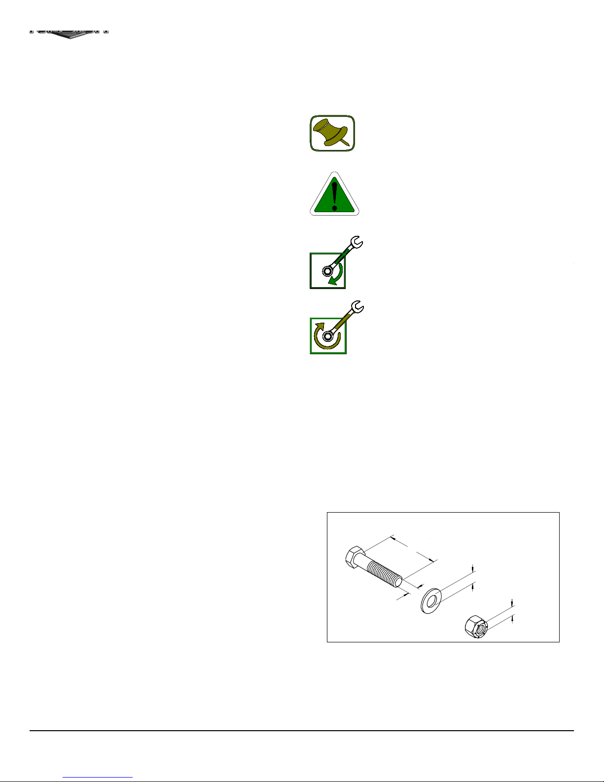
About the Icons
The icons displayed in this Owner’s Manual are used to facilitat
the correct assembly and safe use of this Product, as-well-as t
prevent injury to yourself or anyone else.
Note provides information necessary to properl
complete a procedure or information which wil
make the procedure easier to understand.
Caution indicates a potentially hazardous situa
tion, which, if not avoided, may result in minor o
moderate injury. It may also be used to aler
against unsafe practices.
Loosely Fasten provides a instruction to loosel
fasten (ex: hand tighten) a hardware assembl
only. This instruction is intended for the alignmen
of hardware components during the assembl
process.
Fully Fasten provides a instruction to fully fasten
(ex: completely tighten) a hardware assembly.
rior to the Assembly of the AP-250S_AP-250D
. We advise you to consult your local Tuff Stuff retailer if you
should have a question or problem regarding the proper
assembly of this Unit.
. Consider the complete surface area of the AP-250S_AP-250D.
Use the overhead view on the front page for designing your
layout before assembling. Once the AP-250S_AP-250D has
been fully assembled it will be heavy and difficult to move,
therefore you should assemble the unit in the area where it is to
be used upon completion.
. It is recommended that another person assist you with the
assembly this unit.
. Neatly organize and identify all parts according to the Parts List
on page 31 and the Exploded View Diagram on fold-out page 32.
Tool Requirements
1.One 9/16” combination wrench
2.One 3/4” combination wrench
3.One 7/8” combination wrench
4.One 7/16” combination wrench
5.One 1/2” combination wrench
6.One ratchet
7.One 9/16” socket
8.One 3/4” socket
9.One rubber mallet
0.One flat head steel hammer
1.External retaining-ring pliers
2.Windex or household glass cleaner
3. One can silicone spray/ teflon spray lubricant
4.Multi-purpose grease
5.Measuring tape
6.Masking tape
7.Utility knife
Assembly Notes
1. Read and follow each step of this Assembly Instruction Manual
sequence. Do not skip ahead, as it will result in an improp
assembly or in having to disassemble parts later.
2. During the assembly of this unit you will be instructed to lea
some Hex Head Cap Screws loosely fastened. Naturally, th
will be fully fastened later in the assembly process. This is do
to prevent any difficulty with alignment of some parts during th
assembly.
Hardware Measurement Diagram
SCREW LENGHT
WASHER DIAMETER
SCREW WIDTH
Note: Due to continuing product improvements, specifications and designs are subject to chan
without notice.
Even though we have prepared this manual with extreme care, neither the publisher nor the auth
can accept responsibility for any errors in, or omission from, the information given.
NUT DIAMETER
1
AP-250S_AP-250D Apollo 2-Stack Gym Syste
Page 3
afety First
e
s
e
Safety Precautions
egardless of how enthusiastic you may be about getting on
our equipment and exercising, take the time to ensure that
our safety is not jeopardized. A moment’s lack of attention
an result in an accident, as can failure to observe certain
imple safety precautions.
. Read, study and understand the Owner’s Manual and all the
warning labels on this product. Furthermore, it is
recommended to familiarize yourself and others with the
proper operation and workout recommendations for this Tuff
Stuff product prior to use. Some of this information can be
obtained in this Owner’s Manual, as well as from your local
Tuff Stuff retailer.
. It is imperative that you retain this Owner’s Manual and be
sure all warning labels are legible and intact. Replacement
Owner’s Manuals and labels are available from your local
Tuff Stuff retailer.
. Consult with your physician before beginning any exercise
program.
4. Use proper discretion when children are present.
5. Frayed or worn cables can be dangerous and may caus
injury. Periodically check these cables for any indication o
wear.
6. Keep hands, limbs, loose clothing and long hair well out o
the way of moving parts.
7. Do not attempt to lift more weight than you can control safely
8. Inspect the AP-250S_AP-250D for any sign of wear on parts
hardware becoming loose or cracks on welds. If a problem i
found do not use or allow the machine to be used unti
defective part is repaired or replaced.
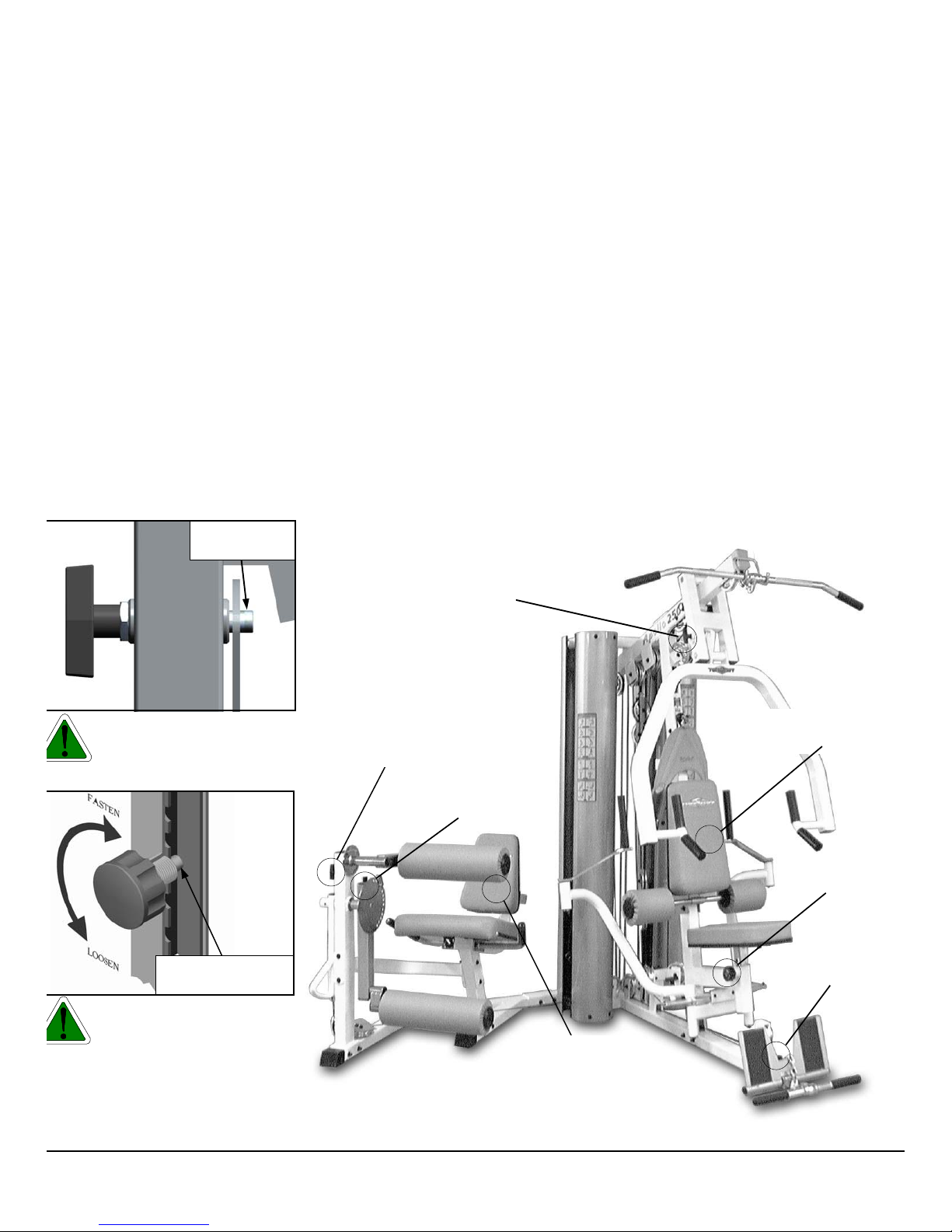
9. Pay special attention to the Push Pull Pins (#73, # 74, #136
#137) and the Turn/Pull Pin w/Knob (#138). Be sure they ar
fully engaged into their corresponding holes. Refer to Fig. 1
and Fig. 2 for further illustration..
Push Pull Pin
Fully Engaged
Fig. 1 Caution: Check the
Push Pull Pins (#73, # 74, #136,
#137) to be fully engaged into their
corresponding holes.
Turn/Pull Pin w/Knob
Fully Engaged
Fig. 2 Caution: Check the
Turn/Pull Pins w/Knob (#138) to
be fully engaged into their corresponding holes
Push-Pull Pin
1/4” X 3 1/2” (#136)
Push-Pull Pin
1/2” X 2 3/4” (#137)
Push-Pull Pin
1/2” X 3 1/2” (#73)
Push-Pull Pin
1/2” X 3 1/2” (#73)
Turn/Pull Pin
W/Knob (#138)
Push-Pull Pin
1/2” X 2 7/8” (#74)
Turn/Pull Pin
W/Knob (#138)
Fig. 3 Picture above depicts the location of the Push Pull Pins
(#73, # 74, #136, #137) and the Turn/Pull Pin w/Knob (#138) on the
unit.
P-250S_AP-250D Apollo 2-Stack Gym System
2
Page 4
q
e
/
m
d
n
e
e
85
m
A3
E3
D2
D1
2
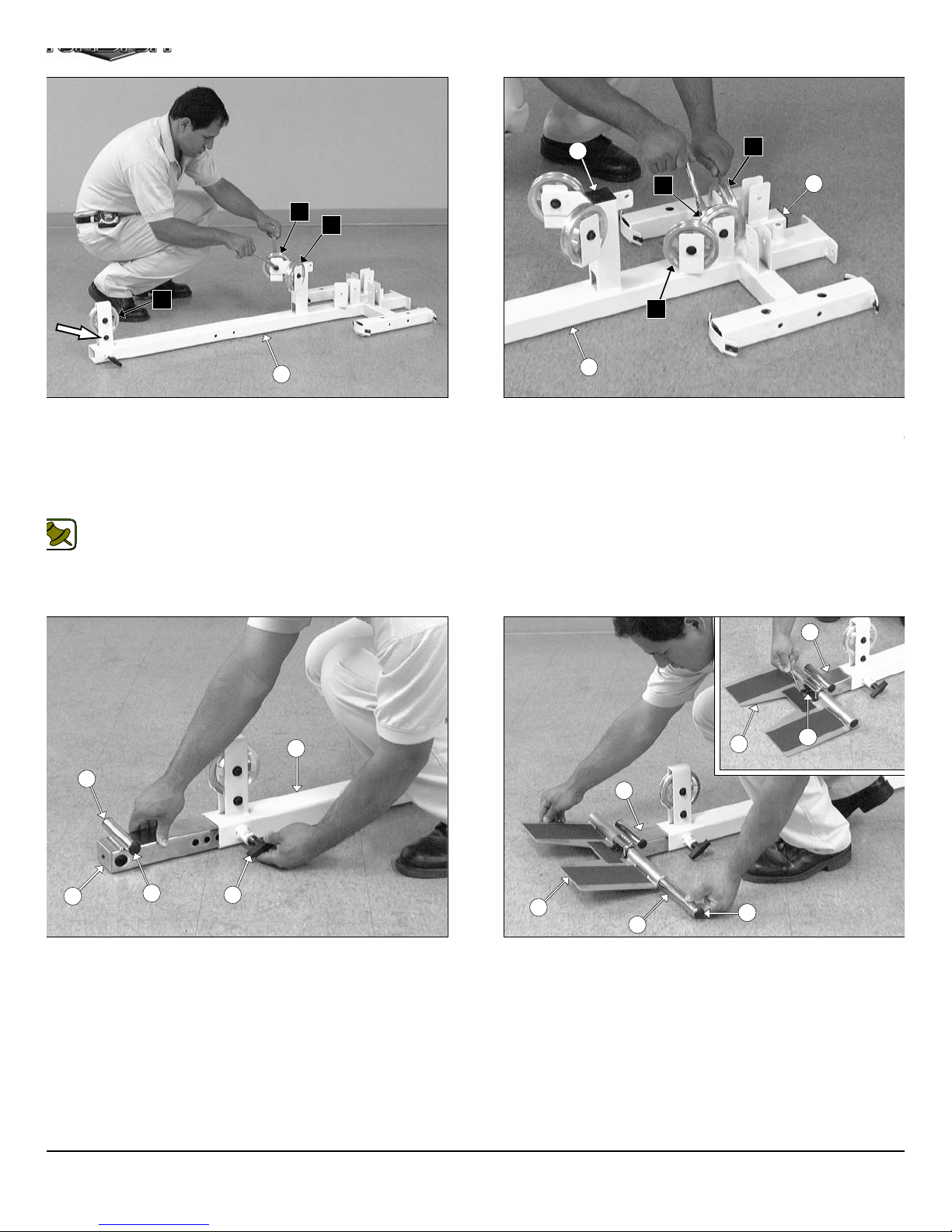
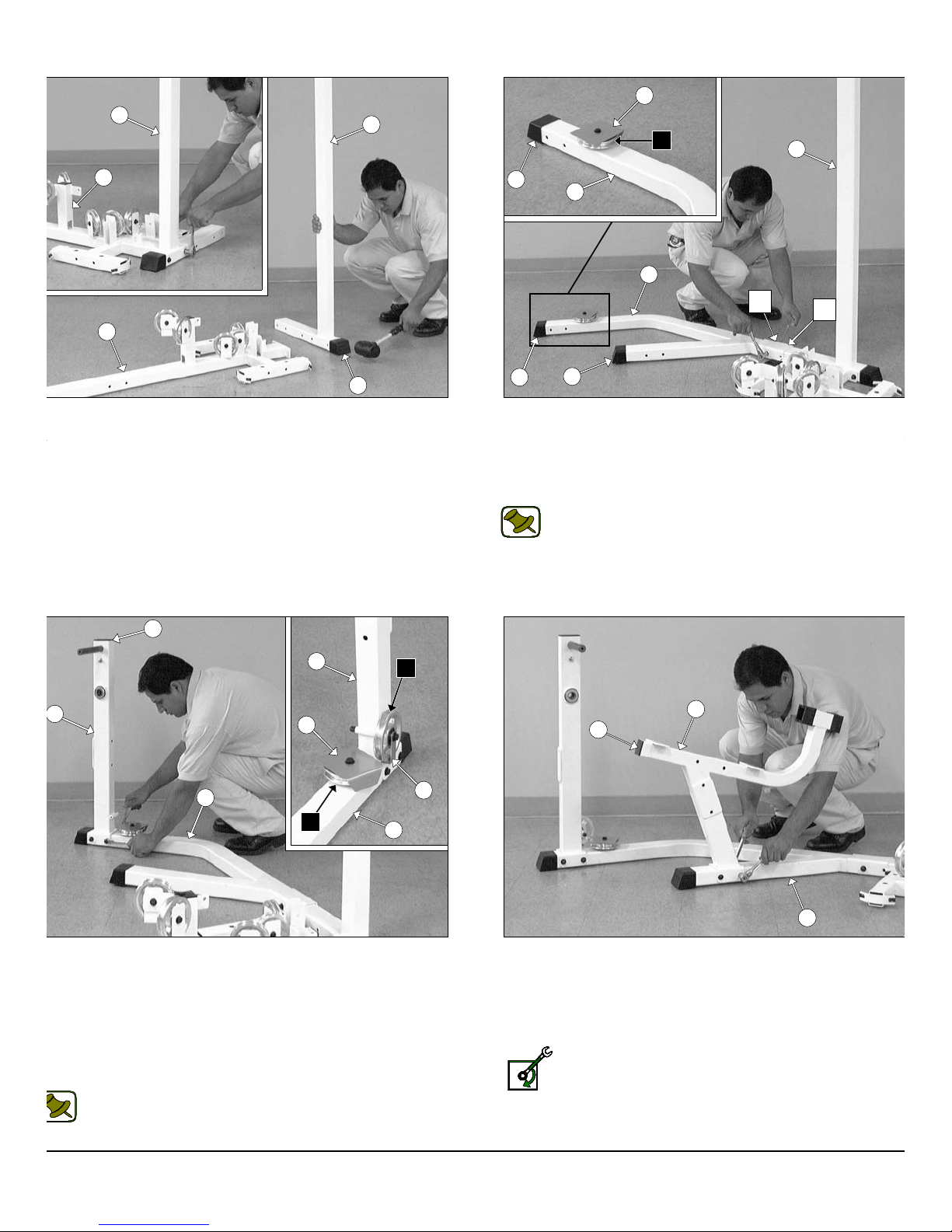
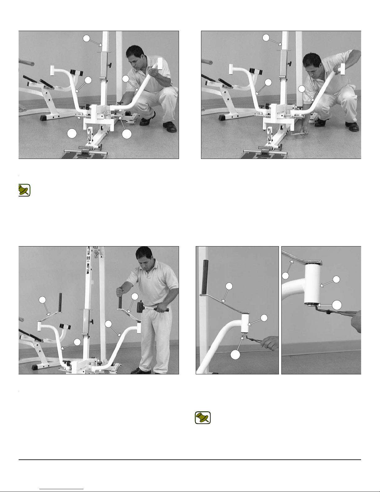
IG. 4 On a flat surface, lay the Base Frame (#2) down and attach
ree Pulleys 4 1/2 Rd (#68-Labeled D1,E1,E3) to the Base Frame (#2)
ing three Hex Head Cap Screws 3/8-16 X 2 (#109), six Flat Washers
AE 3/8” (#91), and three Nylon Insert Jam Lock Nuts 3/8-16 (#101).
ext, affix one Hex Head Cap Screw 3/8-16 X 2 (#109), two Flat
ashers SAE 3/8” (#91), and one Nylon Insert Jam Lock Nut 3/8-16
101) to the bracket in front of the Base Frame (#2).
Note: The black boxed letters pointing to the pulleys are used
throughout this manual as reference to the Cable Mapping
Diagrams on pages 24 - 39. These black boxed letters will be
primarily used for locating certain pulleys during the cable
routing process.
D2
F2
85
2
FIG. 5 Using a rubber mallet, insert two Plastic Insert Caps 2” S
(#85) into the tube-ends of the Base Frame (#2). Next, attach thre
Pulleys 4 1/2 Rd (#68-Labeled A3,D2,F2) to the pulley brackets of th
Base Frame (#2) using three Hex Head Cap Screws 3/8-16 X 1 3
(#110), six Flat Washers SAE 3/8” (#91), and three Nylon Insert Ja
Lock Nuts 3/8-16 (#101).
14
2
89
14
IG. 6 Insert the Low Row Stabilizer (#14) into the receptacle of
e Base Frame (#2). Next, using a rubber mallet, insert two Plastic
sert Caps 1” Rd. (#89) into the tube-ends of the Low Row Stabilizer
14).
89
74
3
15
69
14
15
31
FIG. 7 Using a rubber mallet, insert two Plastic Insert Caps 1” R
(#89) into the tube-ends of the Foot Roll Tube 1X16 (#31). Next, co
nect the Low Row Foot Support (#15) to the Low Row Stabiliz
(#14) using the Foot Roll Tube 1 X 16 (#31). Secure the Foot Ro
Tube 1X16 (#31) to the Low Row Stabilizer (#14) using one S
Screw 3/8-16 X 1/2 (#69), as shown in caption above.
89
AP-250S_AP-250D Apollo 2-Stack Gym Syste
Page 5
q
x
/
c
r
n
O
wner’s Manual: Assembly Instruction
s
w
d
9
)
)
a
a
1
i
v
o
4
4
2
2
57
IG. 8 Using a rubber mallet, insert one Plastic Insert Cap w/ Groove
X 3 (#57) onto the tube-end of Rear Upright (#4). Next, attach the
ear Upright (#4) to the Base Frame (#2) using two Hex Head Cap
crews 3/8-16 X 4 (#105), four Flat Washers SAE 3/8” (#91), and two
ylon Insert Lock Nuts 3/8-16 (#100).
84
11
A1
50
A2
4
57
9
9
st
1
57
FIG. 9 Using a rubber mallet, insert two Plastic Insert Caps
Groove 2 X 3 (#57) onto the tube-ends of the Leg Extension Mai
Frame (#9). Next, attach one Pulley 4 1/2 Rd. (#68-Labeled A2) an
one Pulley Cover Plate (#50) to the Leg Extension Main Frame (#
threaded socket using one Hex Head Cap Screw 3/8-16 X 1 3/4 (#110
one Split Lock Washer 3/8” (#95), and one Flat Washer SAE 3/8” (#91
57
Note: Attach the Leg Extension Main Frame (#9) to the Re
Upright (#4) using ONLY the 1st hole with one Hex Head C
Screw 3/8-16 X 4 1/4 (#104), two Flat Washers SAE 3/8” (#9
and one Nylon Insert Lock Nut 3/8-16 (#100). The other Bolt w
be installed in the 2nd hole once the Weight Shrouds (#22) ha
been assembled onto the unit. Refer to Fig. 82 on page 23 f
further clarification of this assembly.
nd
2
11
9
IG. 10 Next, attach the Leg Extension Front Frame (#11) to the
g Extension Main Frame (#9) using two Hex Head Cap Screws 3/8-
X 4 1/4 (#104), four Flat Washers SAE 3/8” (#91), and two Nylon
sert Lock Nuts 3/8-16 (#100). Next, attach one Pulley 4 1/2 Rd. (#68-
beled A1) and one Cable Retainer L-Shaped Bracket (#28) to the
g Extension Front Frame (#11) using one Hex Head Cap Screw
8-16 X 4 1/4 (#105), one Flat Washer SAE 3/8” (#91), and one Nylon
sert Lock Nut 3/8-16 (#100). Refer to Fig. 86 on page 30 for further
ustration of this hardware assembly.
Note: Be sure the Cable Retainer L-Shaped Bracket (#28) is
positioned as shown in caption above.
50
A2
28
9
12
85
9
FIG. 11 Using a rubber mallet, insert one Plastic Insert Cap 2” S
(#85) into the tube-end of the Leg Extension Seat Frame (#12).Ne
attach the Leg Extension Seat Frame (#12) to the Leg Extensio
Main Frame (#9) using two Hex Head Cap Screws 3/8-16 X 4 1
(#104), four Flat Washers SAE 3/8” (#91) and two Nylon Insert Lo
Nuts 3/8-16 (#100).
Loosely Fasten: Do not completely fasten this hardwa
assembly at this time, as it will be completely fastened later i
the assembly process.
P-250S_AP-250D Apollo 2-Stack Gym System
4
Page 6
8
o
a
a
t
11
m
13
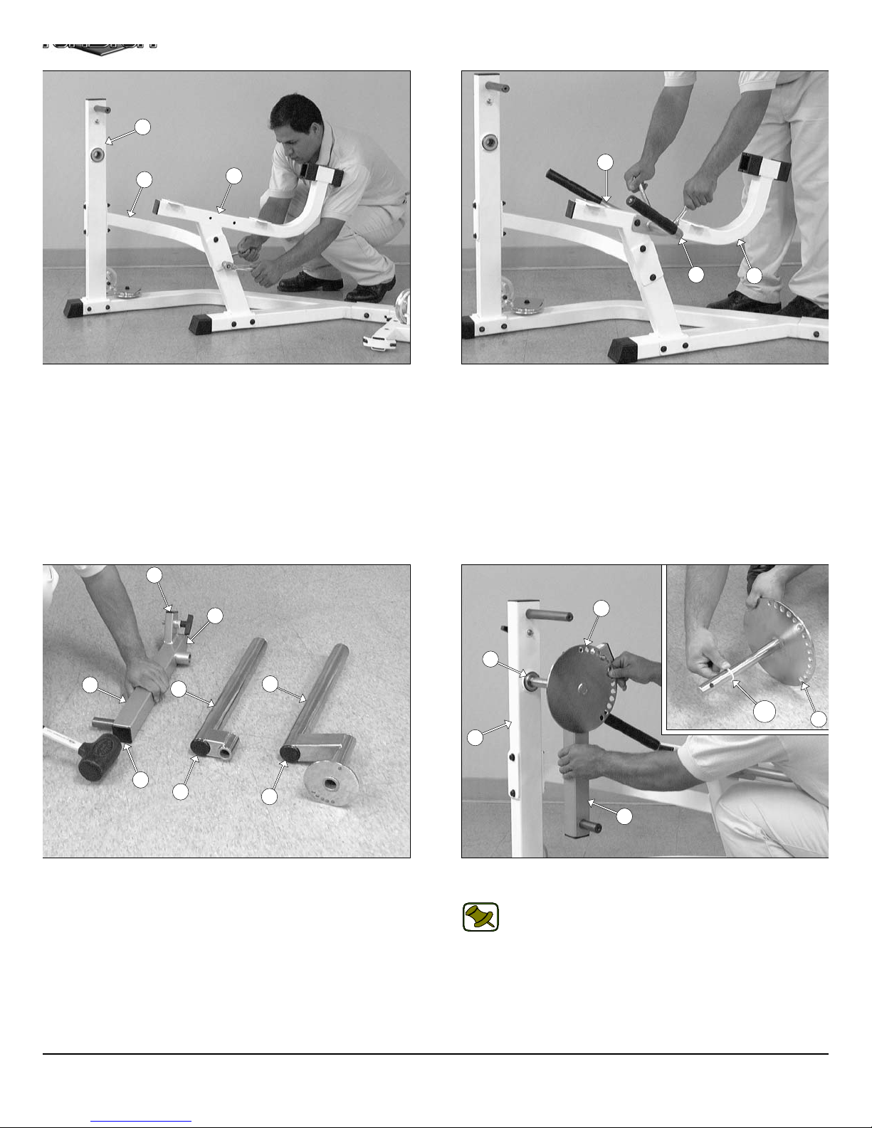
IG. 12 Next, attach the Leg Extension Arm Support (#13) to the
g Extension Front Frame (#11) using two Hex Head Cap Screws
8-16 X 4 1/4 (#104), four Flat Washers SAE 3/8” (#91), and two Nylon
sert Lock Nuts 3/8-16 (#100). Next, attach the other end of the Leg
xtension Arm Support (#13) to the Leg Extension Seat Frame
12) using two Hex Head Cap Screws 3/8-16 X 3 1/4 (#106), four Flat
ashers SAE 3/8” (#91), and two Nylon Insert Lock Nuts 3/8-16
100).
12
87
45
46
FIG. 13 Attach the Leg Extension Right Handle (#45) and the Le
Extension Left Handle (#46) to the Leg Extension Seat Frame (#12
in the position as shown above, using two Hex Head Cap Screws 3/
16 X 3 1/4 (#106), four Flat Washers SAE 3/8” (#91), and two Nyl
Insert Lock Nuts 3/8-16 (#100).
12
85
25
29
32
85
88
IG. 14 Using a rubber mallet, insert two Plastic Insert Caps 2” Sq.
85), and one Plastic Insert Cap 1 X 2 (#87) into the tube-ends of the
ivot-Arm (#25). Next, insert one Plastic Insert Cap 2” Rd. (#88) into
e tube-end of the Swivel Foam Roll Tube (#29), and the Top Adj.
g Hold-Down Tube (#32).
88
16
61
122
16
11
25
FIG. 15 Insert a Nylon Washer 1 X 1 1/4 (#122) to the Circul
Plate w/ Axle (#16) as shown in caption above.
Note: It is recommended to lubricate the axle on the Circul
Plate w/ Axle (#16) with multi-purpose grease prior
assembling.
Next, attach the Pivot-Arm (#25) to the Circular Plate w/ Axle (#16)
Then, insert the Circular Plate w/ Axle (#16) into the Ball Bearin
housing of the Leg Extension Front Frame (#11).
5
AP-250S_AP-250D Apollo 2-Stack Gym Syste
Page 7
t
w
e
X
w
y
n
)
t
O
wner’s Manual: Assembly Instruction
s
87
123
16
43
25
IG. 16 Attach the Actuator Arm (#43) to the axle of the Circular
late (#16). Next, align the hole of the Actuator Arm (#43) with the
le of the axle of the Circular Plate (#16) and, using a hammer, insert
e Roll Pin 3/8 X 1 1/2 (#123). Be sure that the Roll Pin 3/8 X 1 1/2
123) is aligned with the holes before hammering into place. In
dition, make sure the Roll Pin 3/8 X 1 1/2 (#123), after hammered in,
comes flush on both sides of the Actuator Arm (#43). Next, using a
bber mallet, insert one Plastic Insert Cap 1 X 2 (#87) into the tube-
dof the Actuator Arm (#43).
32
11
25
29
FIG. 17 Next, attach the Top Adjustable Leg Holder Tube (#32)
the Leg Extension Front Frame (#11) using one Hex Head Cap Scre
3/8-16 X 1 (#113), one Split Lock Washer 3/8” (#95), and one Fend
Washer 3/8 X 1 1/2 (#92). Next, attach the Swivel Foam Roll Tub
(#29) to the Pivot- Arm (#25) using one Hex Head Cap Screw 3/8-16
1 (#113), one Split Washer 3/8” (#95), and one Fender W asher 3/8 X
1/2 (#92).
3
85
2
IG. 18 Caution: It is strongly recommended to use another
ttach the Front Frame (#3) to the Base Frame (#2) using two Hex
ead Cap Screws 3/8-16 X 4 1/4 (#104), four Flat Washers SAE
8” (#91) and two Nylon Insert Lock Nuts 3/8-16 (#100). Next, using a
bber mallet, insert one Plastic Insert Cap 2” Sq. (#85) into the tube-
d of the Front Frame (#3).
person in assisting with this assembly.
28
C4
C6
D7
FIG. 19 Next, attach one Pulley 4 1/2” Rd. (#68-Labeled C4), an
one Cable Retainer L-Shaped Bracket (#28), in the position as sho
above, to the plate of the Front Upright (#3) using one Hex Head Ca
Screw 3/8-16 X 1 3/4 (#110), two Flat Washers SAE 3/8” (#91), an
one Nylon Insert Jam Lock Nut 3/8-16 (#101). Next, attach two Pulle
4 1/2” Rd. (#68-Labeled C6,D7) to the pulley brackets of the Fro
Upright (#3) using two Hex Head Cap Screws 3/8-16 X 2 1/2 (#108
four Flat Washers SAE 3/8” (#91), and two Nylon Insert Jam Lock Nu
3/8-16 (#101).
3
P-250S_AP-250D Apollo 2-Stack Gym System
6
Page 8
a
)
8
r
e
m
L
5
m
5
3
IG. 20 Caution: It is strongly recommended to use another
ttach the Top Pulley Assembly (#5) to the Front Upight (#3) using
o Hex Head Cap Screws 3/8-16 X 4 1/4 (#104), four Flat Washers
AE 3/8” (#91), and two Nylon Insert Lock Nuts 3/8-16 (#100).
person in assisting with this assembly.
Loosely Fasten: Do not completely fasten this hardware
assembly at this time, as it will be completely fastened later in
the assembly process.
19
C1
5
3
FIG. 21 Next, attach the Top Pulley Assembly (#5) to the Re
Upright (#4) using two Hex Head Cap Screws 3/8-16 X 3 1/4 (#106
four Flat Washers SAE 3/8” (#91) and two Nylon Insert Lock Nuts 3/
16 (#100).
Fully Fasten: Proceed to align and fully fasten this hardwa
assembly and all the previous assemblies that were l
loosely fastened.
4
5
28
D5
C7
D3
IG. 22 Attach four Pulleys 4 1/2 Rd. (#68-Labeled D5, C7, D3, C8)
the pulley brackets of the Top Pulley Assembly (#5) using two Hex
ead Cap Screws 3/8-16 X 2 3/4 (#107), four Flat Washers SAE
8” (#91), and two Nylon Insert Jam Lock Nuts 3/8-16 (#101). Next,
tach another Pulley 4 1/2 Rd (#68-Labeled C1) to the Top Pulley As-
mbly (#5) using one Hex Head Cap Screw 3/8-16 X 2 1/2 (#108),
o Flat Washers SAE 3/8” (#91), and one Nylon Insert Jam Lock Nut
8-16 (#101). Next, attach the Lat Bar Holder 2 X 3 (#19) to the Top
ulley Assembly (#5) using one Hex Head Cap Screw 3/8-16 X 2 3/4
107), two Flat Washers SAE 3/8” (#91), and one Nylon Insert Jam
ck Nut 3/8-16 (#101).
7
C8
A4
FIG. 23 Next, attach one Pulley 4 1/2 Rd. (#68- Labeled A4), an
one Cable Retainer L-Shaped Bracket (#28) to the pulley plate of th
Top Pulley Assembly (#5) using one Hex Head Cap Screw 3/8-16 X
3/4 (#110), two Flat Washers SAE 3/8” (#91), and one Nylon Insert Ja
Lock Nut 3/8-16 (#101). Be sure to position the Cable Retainer
Shaped Bracket (#28) as shown above.
AP-250S_AP-250D Apollo 2-Stack Gym Syste
Page 9
e
b
w
o
e
O
wner’s Manual: Assembly Instruction
s
3
6
144
IG. 24 Insert the Left Pec Dec Arm (#7) along with the Aluminum
am Plate (#144) into the receptacle of the Front Upright (#3).
epeat the same procedure for the Right Pec Dec Arm (#6).
Note: It is recommended to grease both axles of the Left and
Right Pec Dec Arms (#7,#6) with multi-purpose grease prior to
assembling.
7
144
3
6
7
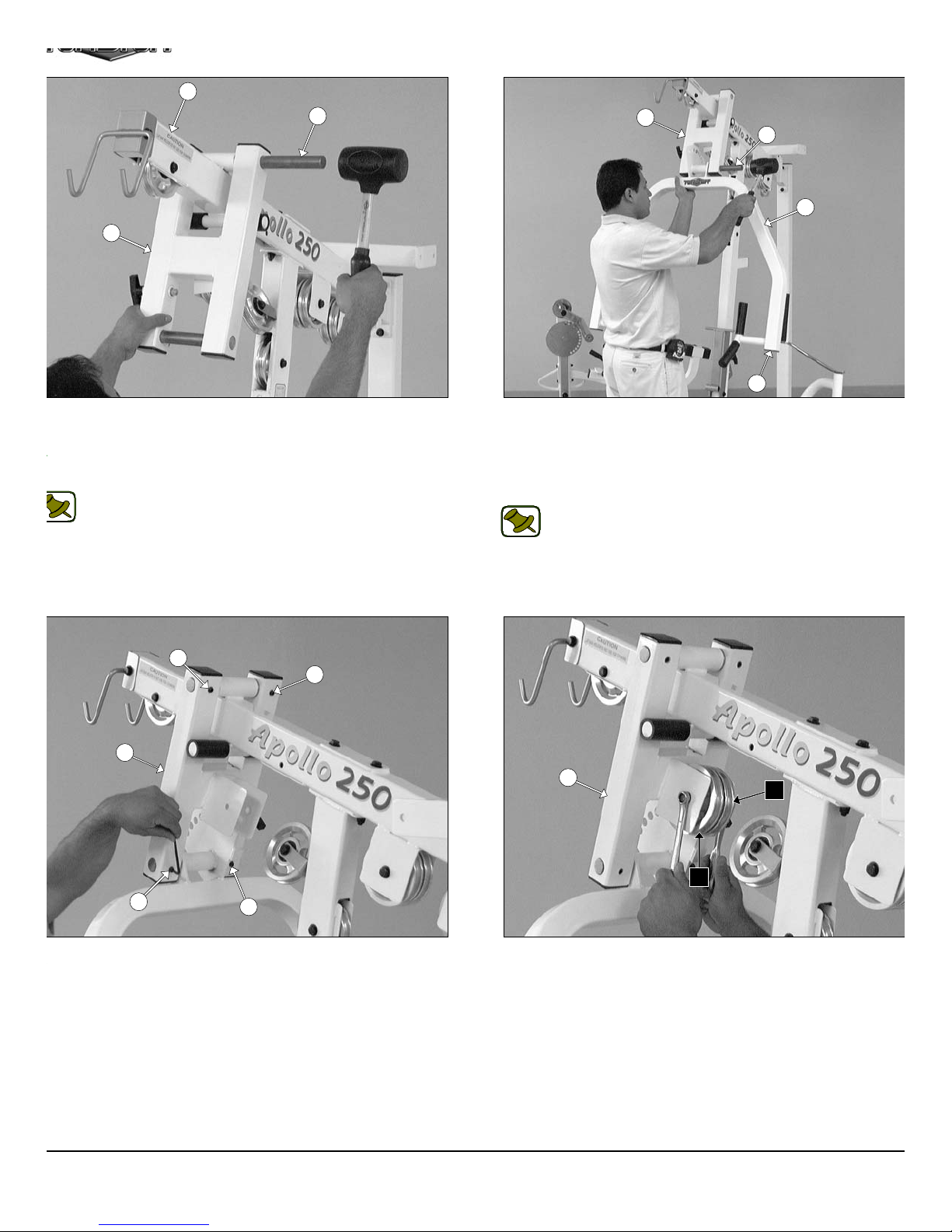
FIG. 25 Secure the Left Pec Dec Arm (#7) into place using on
Hex Head Cap Screw 3/8-16 X 1 (#113), one Split Lock Wash
3/8” (#95), and one Fender Washer 3/8 X 1 1/2 (#92). Repeat th
same procedure for the Right Pec Dec Arm (#6).
8
8
7
6
IG. 26 Using a rubber mallet, insert a Pec Dec Swivel Handle
8), in the position as shown above, into the Left Pec Dec Arm (#7).
epeat the same procedure for the Right Pec Dec Arm (#6).
8
7
8
115
7
115
FIG. 27 Next, secure the Pec Dec Swivel Handles (#8) using two R
taining Snap Rings (#115). If possible, use Snap Ring Pliers for this jo
as shown above. If the tool is not available, carefully work each Retainin
Snap Ring (#115) into the groove, then push up alternately with a scre
driver working the Retaining Snap Ring (#115) into the groove.
Note: Be careful not to distort the Retaining Snap Rings (#115)
bend them.
P-250S_AP-250D Apollo 2-Stack Gym System
8
Page 10
q
a
i
a
5
m
18
17
IG. 28 Using a rubber mallet, insert one Pivot Axle 1 X 8 1/8 (#18)
rough the holes of the Press Bar Selector Housing (#17) and
rough the receptacle of the Top Pulley Housing (#5) until the Pivot
xle 1 X 8 1/8 (#18) is flush with both sides of the Press Bar Selector
ousing (#17).
Note: It is recommended to grease the Pivot Axles 1 X 8 1/8
(#18) with multi-purpose grease prior to assembling.
17
18
1
85
FIG. 29 Using a rubber mallet, insert two Plastic Insert Caps 2” S
(#86) into the tube-ends of the Press Bar (#1). Next, insert the Pres
Bar (#1) up into the Press Bar Selector Housing (#17) and support i
into place using the push-pull pin 1/2 X 3 1/2 (#73). Next, using
rubber mallet, insert the Pivot Axle 1 X 8 1/8 (#18) into the Press B
Selector Housing (#17) and through the Press Bar (#1).
Note: Refer to Fig. 83 on page 30 for further clarification of th
assembly.
69
69
17
69
IG. 30 Secure the two Pivot Axles 1 X 8 1/8 (#18) to the Press
ar Selector Housing (#17) using four Set Screws 3/8-16 X 1/2 (#69).
se the Supplied Hex Key 3/16 (#126) for securing these Set Screws
8-16 X 1/2 (#69) into the threaded sockets on the Press Bar Selector
ousing (#17). Next, clean the ends of the Pivot Axles 1 X 8 1/8
18) and apply four 1” Rd. Silver Mylar Decals (#131–Not shown).
hese decals are used to hide and protect the ends of the axles.
69
17
C3
FIG. 31 Next, attach two Pulleys 4 1/2 Rd. (#68-Labeled C3, C5) t
the Press Bar Selector Housing (#17) using one Hex Head C
Screw 3/8-16 X 2 3/4 (#107), two Flat Washers SAE 3/8” (#91), an
one Nylon Insert Jam Lock Nut 3/8-16 (#101).
C5
9
AP-250S_AP-250D Apollo 2-Stack Gym Syste
Page 11
v
s
e
r
v
e
E
a
r
i
O
wner’s Manual: Assembly Instruction
s
21
21
81
81
2
81
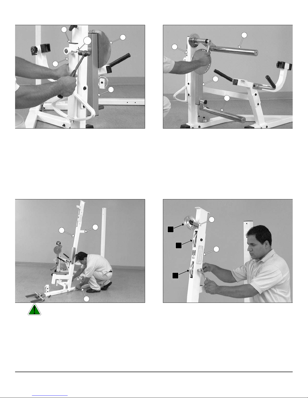
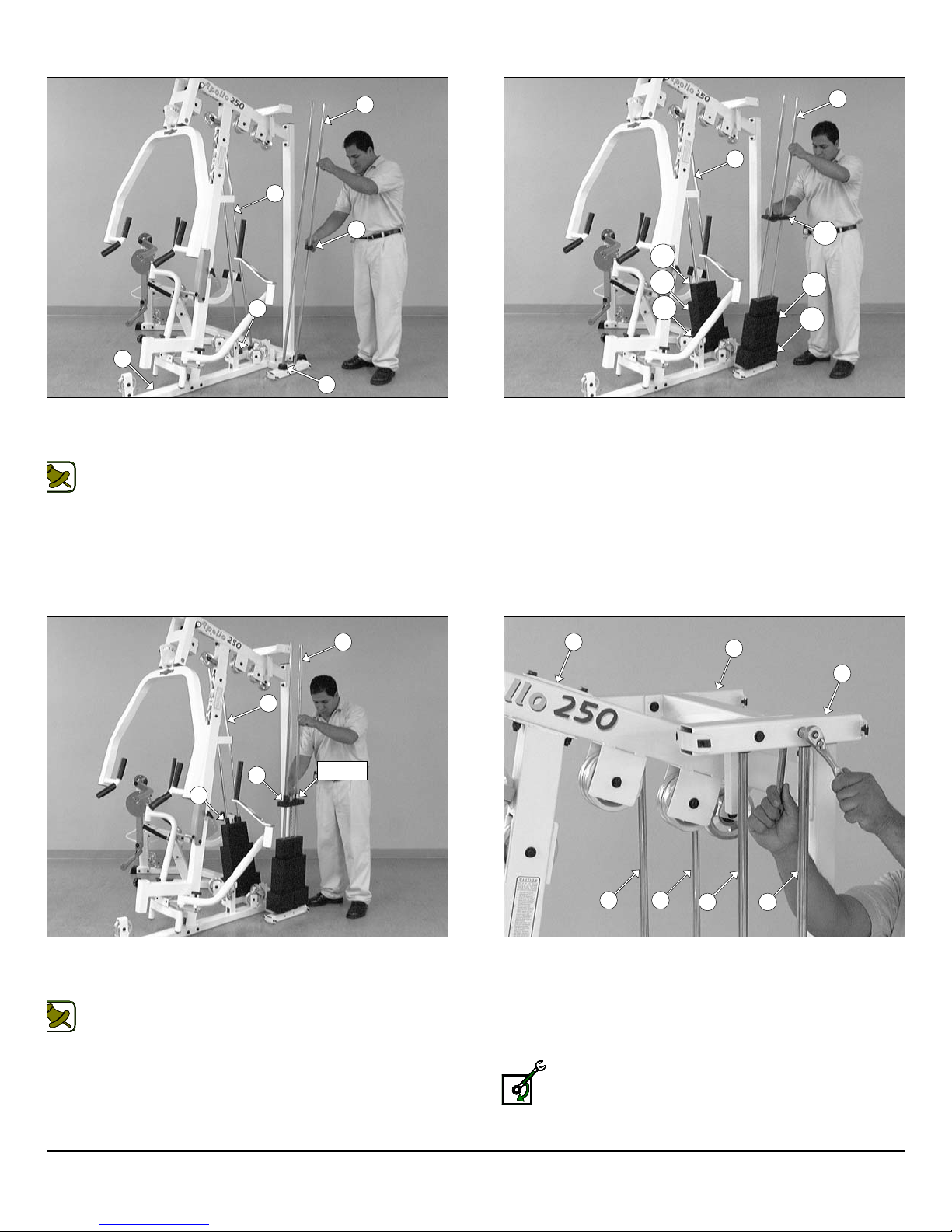
IG. 32 Insert the four Guide Rods 3/4 X 72 (#21) into the
ceptacles of the Base Frame (#2), as shown above. Next, insert four
ubber Donuts 3/4 X 2 1/2 (#81) onto the Guide Rod 3/4 X 72 (#21).
Note: Lubricate the Guide Rods 3/4 X 72 (#21) with a silcone or
teflon lubricant at this time.
21
21
133
133
23
134
FIG. 33 Carefully begin sliding the Weight Plates over the Guid
Rods (#21) beginning with the five 15 Lb. Weight Plates (#134) at th
bottom, the nine 10 Lb. Weight Plates (#23) in the middle, and the fi
5 Lb. Weight Plates (#133) on top of the weight stack. Same proce
for both weight stacks.
23
134
21
21
24
LABEL
24
IG. 34 Slide the Top Plate/Selector Bar (#24) over the Guide
ods (#21) allowing it to come to rest on top of the completed weight
ack. Same process for both weight stacks.
Note: Be sure the Label located on the Top Plate/Selector Bar
(#24) is facing out, as shown above, before sliding the Top
Plate/Selector Bar (#24) onto the Guide Rods (#21).
5
20
20
2121
21
FIG. 35 Maneuver the two Guide Rods (#21) into the holes on th
bottom side of the Guide Rod Retainer Housing (#20). Next, secu
the Guide Rod Retainer Housing (#20) along with the two capti
Guide Rods (#21) to the Top Pulley Assembly (#5) using two H
Head Cap Screws 3/8-16 X 2 3/4 (#107), four Flat Washers SA
3/8” (#91), and two Nylon Insert Jam Lock Nuts 3/8-16 (#101). Repe
the same procedure for the other Guide Rod Retainer Housing (#20)
Loosely Fasten: Do not completely fasten this hardwa
assembly at this time, as it will be completely fastened later
the assembly process.
21
P-250S_AP-250D Apollo 2-Stack Gym System
10
Page 12
e
r
i
o
116
m
MASKING
TAPE
133
23
116
24
24
83
24
83
134
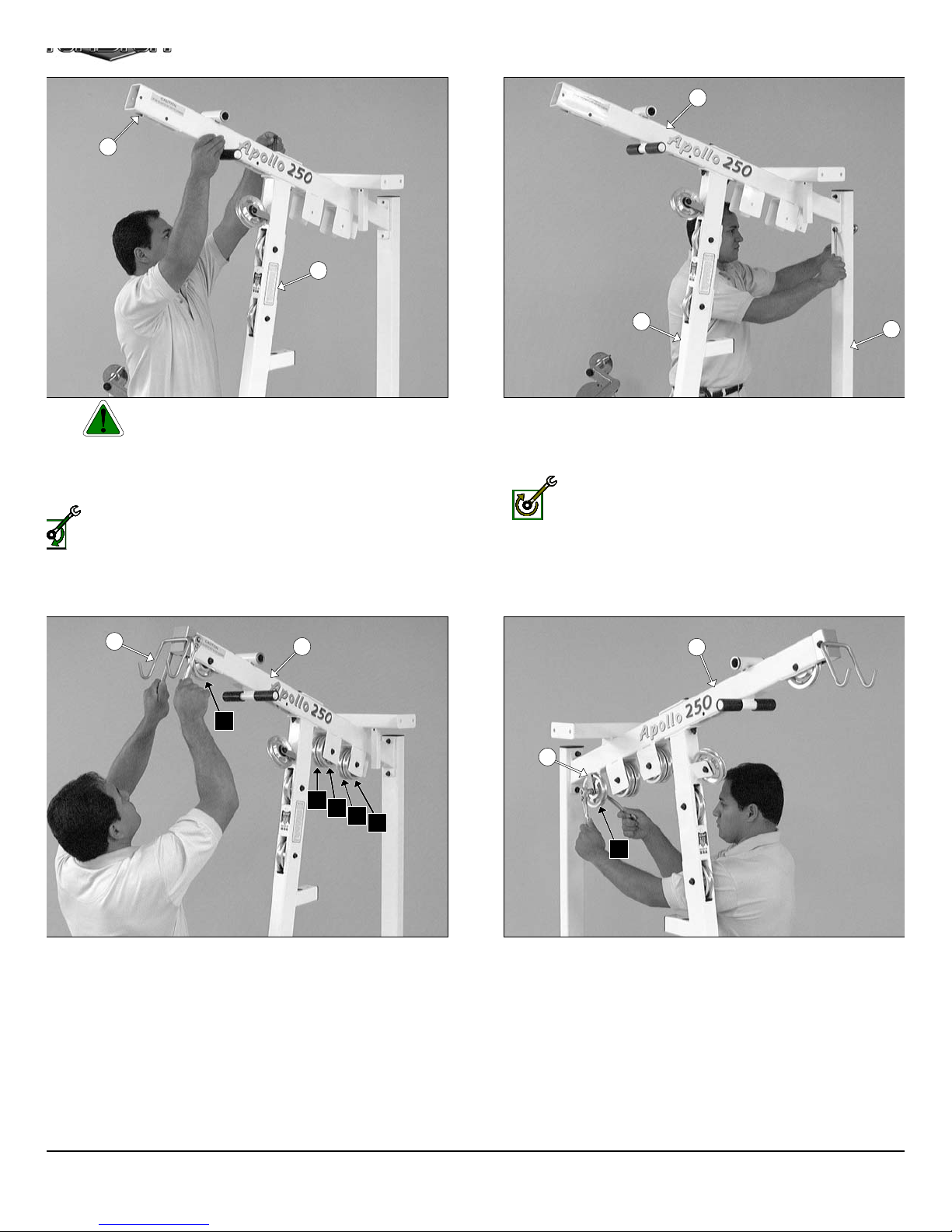
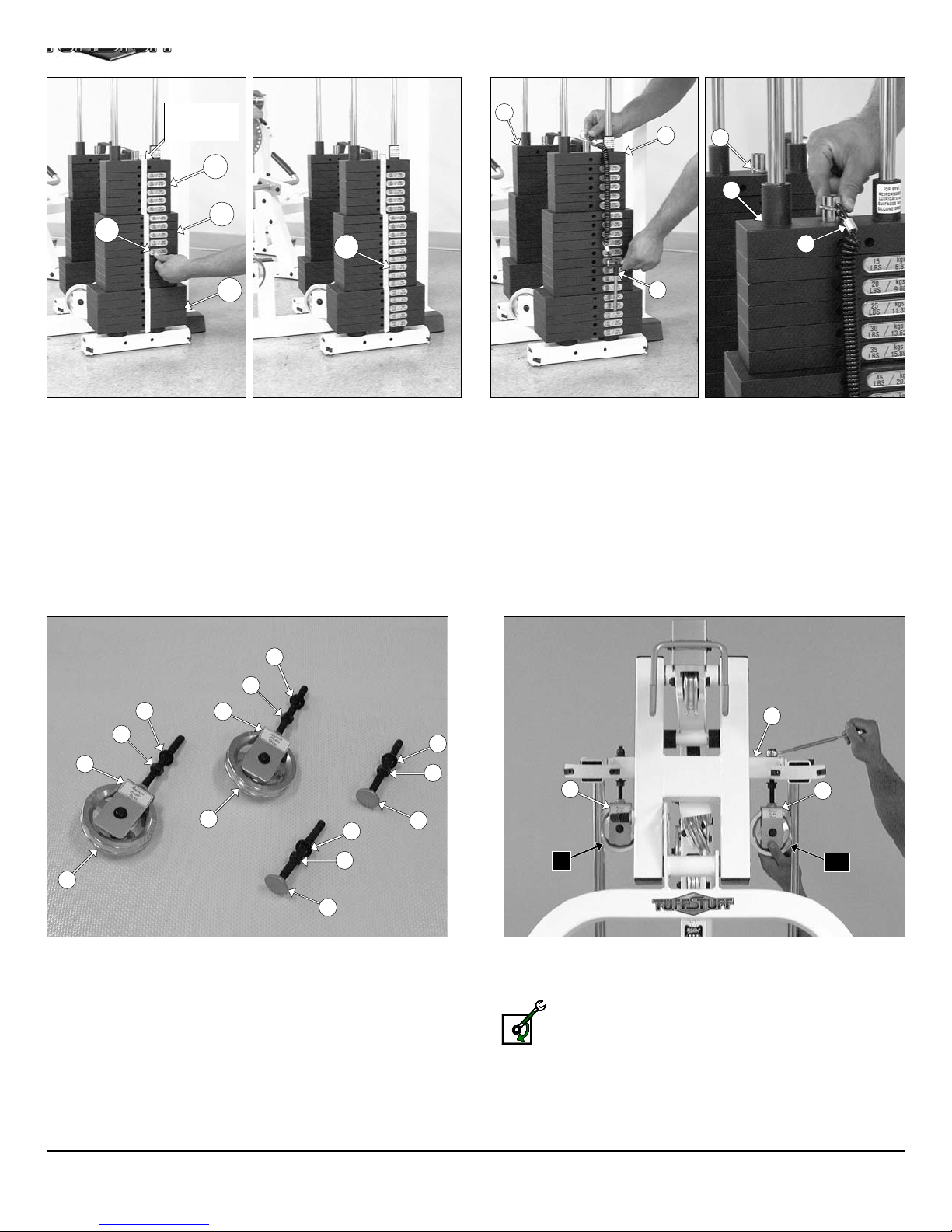
IG. 36 To attach the Decal-Numbers we recommend using a piece of
asking tape as a guide to vertically align the Decal-Numbers. Attach the
ecal Weight Numbers (#116) to the Weight Plates (#133, #23, #134) in
e corresponding order. Begin with the 15 at the top, 20 next, and so on.
90
99
90
99
36
36
90
99
83
FIG. 37 Next, attach the Selector Pins w/Coil (#83) to the Select
Bars (#24).
5
36
36
68
90
99
68
33
IG. 38 Locate the two Adjustable Pulley Brackets (#36) and at-
ch two Pulleys 4 1/2 Rd. (#68) using two Hex Head Cap Screws 3/8-
X 1 3/4 (#110), four Flat Washers SAE 3/8” (#91), and two Nylon
sert Jam Lock Nuts 3/8-16 (#101). Next, thread two Regular Hex
uts 1/2-13 (#99) and insert two Flat Washers SAE 1/2” (#90) over the
lts of the Adjustable Pulley Brackets (#36). Next, locate the two
djustable Stoppers (#33) and thread one Regular Hex Nut 1/2-13
99) and insert one Flat Washer SAE 1/2” (#90) over each of the bolts,
shown above.
11
33
A6
FIG. 39 Attach the two Adjustable Pulley Brackets (#36) to th
Top Pulley Assembly (#5) using two Flat Washers SAE 1/2” (#90) an
two Nylon Insert Lock Nuts 1/2-13 (#98).
Loosely Fasten: Do not completely fasten this hardwa
assembly at this time, as it will be completely fastened later
the assembly process.
C10
AP-250S_AP-250D Apollo 2-Stack Gym Syste
Page 13

6
u
h
8
e
1
o
1
O
wner’s Manual: Assembly Instruction
s
5
26
27
3
33
33
IG. 40 Next, thread one Adjustable Stopper (#33) into the threaded
cket located on the Top Pulley Housing (#5), as shown in the left
cture above. Next, insert the other Adjustable Stopper (#33) into the
ceptacle located on the Front Upright (#3) and secure it into place
ing one Flat Washer SAE 1/2” (#90), and one Regular Hex Nut 1/2-13
99).
Loosely Fasten: Do not completely fasten this hardware
assembly at this time, as it will be completely fastened later in the
assembly process.
68
68
27
26
68
68
FIG. 41 Locate the two Closed-End Double Pulley Brackets (#2
and attach four Pulleys 4 1/2 Rd. (#68) using four Hex Head Ca
Screws 3/8-16 X 1 3/4 (#110), eight Flat Washers SAE 3/8” (#91), an
four Nylon Insert Jam Lock Nuts 3/8-16 (#101). Next, locate the fo
Adjustable Double Pulley Plates (#27) and attach four Pulleys 4 1/
Rd. (#68) using four Hex Head Cap Screws 3/8-16 X 1 3/4 (#110), eig
Flat Washers SAE 3/8” (#91), and four Nylon Insert Jam Lock Nuts 3/
16 (#101).
Note: The four holes on the Adjustable Double Pulley Plat
(#27) are used to adjust the cable tension once the cable routin
has been completed.
43
41
50
A2
IG. 42 Attach the looped-end of the Leg Extension Cable (#41) to
e bracket of the Actuator Arm (#43) using one Hex Head Cap Screw
8-16 X 1 (#113), and one Nylon Insert Jam Lock Nut 3/8-16 (#101).
oute the Leg Extension Cable (#41) under the Pulley 4 1/2 Rd. (#68-
beled A1), then route between the Pulley 4 1/2 Rd. (#68-Labeled A2)
d the Pulley Cover Plate (#50).
Note: Refer to the Cable Mapping Diagram on page 24 for
further detailed illustration of the Leg Extension Cable (#41)
routing.
A1
28
P-250S_AP-250D Apollo 2-Stack Gym System
41
A3
2
A2
FIG. 43 Next, continue to route the Leg Extension Cable (#4
under the Nylon Pulley 4 1/2 Rd. (#68-Labeled A3) located on the Bas
Frame (#2).
Note: Refer to the Cable Mapping Diagram on page 24 f
further detailed illustration of the Leg Extension Cable (#4
routing.
12
Page 14

t
d
o
1
a
c
i
41
m
28
5
36
A6
A4
A4
41
A5
27
IG. 44 Route the Leg Extension Cable (#41) up and over the
ulley 4 1/2 Rd. (#68-Labeled A4) located on the Top Pulley Housing
5).
Note: Refer to the Cable Mapping Diagram on page 24 for
further detailed illustration of the Leg Extension Cable (#41)
routing.
41
24
FIG. 45 Next, locate the assembled Adjustable Double Pulle
Plates (#27) and route the Leg Extension Cable (#41) down an
under the Pulley 4 1/2 Rd. (#68-Labeled A5). Next, continue to rou
the Leg Extension Cable (#41) up and over the Nylon Pulley 4 1/2 R
(#68-Labeled A6).
Note: Refer to the Cable Mapping Diagram on page 24 f
further detailed illustration of the Leg Extension Cable (#4
routing.
42
IG. 46 Next, attach the Leg Extension Cable (#41) to the Top
late/ Selector Bar (#24) using one Split Bolt 1/2-13 X 1 (#94) and one
plit Lock Washer 1/2” (#93).
Note: Refer to Fig. A on page 24 for further clarification of this
hardware assembly.
Fully Fasten: Proceed to fully fasten this hardware assembly.
13
2
FIG. 47 Attach the looped end of the Leg Extension Tension Cabl
(#42) to the pulley bracket of the Base Frame (#2) using one Hex He
Cap Screw 3/8-16 X 1 3/4 (#110), two Flat Washers SAE 3/8” (#91
two Nylon Spacers 3/8 X 3/8 (#120), and one Nylon Insert Jam Lo
Nut 3/8-16 (#101).
Note: Refer to Fig. A on page 25 for further clarification of th
hardware assembly.
AP-250S_AP-250D Apollo 2-Stack Gym Syste
Page 15

2
2
a
a
o
O
wner’s Manual: Assembly Instruction
s
A5
B1
42
IG. 48 Next, continue to route the Leg Extension Tension Cable
42) up and over the Pulley 4 1/2 Rd. (#68-Labeled B1).
Note: Refer to the Cable Mapping Diagram on page 25 for
further detailed illustration of the Leg Extension Tension Cable
(#42) routing.
42
2
FIG. 49 Attach the end of the Leg Extension Tension Cable (#4
to the threaded socket of the Base Frame (#2) using one Split Bolt 1/
13 X 1 (#94), and one Split Lock Washer 1/2” (#93).
Note: Refer to Fig. B on page 25 for further clarification of thi
hardware assembly.
Fully Fasten: Proceed to fully fasten this hardware assembly.
5
C1
37
IG. 50 Begin routing the Lat Cable (#37) up and over the Pulley 4
2 Rd. (#68-Labeled C1) and into the tube of the Top Pulley
ssembly (#5). Then, pull the Lat Cable (#37) down through the
ening at the bottom of the Top Pulley Assembly (#5).
Note: Refer to the Cable Mapping Diagram on page 26 for
further detailed illustration of the Lat Cable (#37) routing.
5
C1
C2
37
FIG. 51 Insert a Pulley 4 1/2 Rd. (#68-Labeled C2) into the slot
the bottom of the Top Pulley assembly (#5) and secure it into plac
using one Hex Head Cap Screw 3/8-16 X 2 1/2 (#108), two Fl
Washers SAE 3/8” (#91), and one Nylon Insert Jam Lock Nut 3/8-1
(#101). Be sure the cable is routed properly into the groove of the Pu
ley 4 1/2 Rd. (#68-Labeled C2).
Note: Refer to the Cable Mapping Diagram on page 26 f
further detailed illustration of the Lat Cable (#37) routing.
P-250S_AP-250D Apollo 2-Stack Gym System
14
Page 16

o
o
c
17
m
17
C2
C4
37
C3
28
3
IG. 52 Next, continue to route the Lat Cable (#37) around the
ulley 4 1/2 Rd. (#68-Labeled C3), then across and over the Pulley 4
2 Rd. (#68-Labeled C4).
Note: Refer to the Cable Mapping Diagram on page 26 for
further detailed illustration of the Lat Cable (#37) routing.
C5
37
C6
3
FIG. 53 Next, continue to route the Lat Cable (#37) over the Pulley
1/2 Rd. (#68-Labeled C5), then through the Front Upright (#3) an
under the Pulley 4 1/2 Rd. (#68-Labeled C6).
Note: Refer to the Cable Mapping Diagram on page 26 f
further detailed illustration of the Lat Cable (#37) routing.
5
36
C10
C7
C8
C6
C9
37
27
IG. 54 Route the Lat Cable (#37) over the Pulleys 4 1/2 Rd. (#68-
beled C7, C8). Next, locate one of the Closed-End Double Pulley
rackets (#26) and continue to route the Lat Cable (#37) down and
der the Pulley 4 1/2 Rd. (#68-Labeled C9), then up and over the
ulley 4 1/2 Rd. (#68-Labeled C10).
Note: Refer to the Cable Mapping Diagram on page 26 for
further detailed illustration of the Lat Cable (#37) routing.
37
24
FIG. 55 Next, attach the Lat Cable (#37) to the Top Plate/ Select
Bar (#24) using one Split Bolt 1/2-13 X 1 (#94), and one Split Lo
Washer 1/2” (#93).
Note: Refer to Fig. B on page 26 for further clarification of thi
hardware assembly.
Fully Fasten: Proceed to fully fasten this hardware assembly.
15
AP-250S_AP-250D Apollo 2-Stack Gym Syste
Page 17

8
4
o
l
s
w
d
a
o
l
O
wner’s Manual: Assembly Instruction
s
38
D1
109
2
IG. 56 Next, begin routing the Low Row/Abdominal Cable (#38)
tween the Pulley 4 1/2 Rd. (#68–Labeled D1) and the Hex Head Cap
crew 3/8-16 X 2 (#109) as shown above.
Note: Refer to the Cable Mapping Diagram on page 27 for
further detailed illustration of the Low Row/Abdominal Cable
(#38) routing
38
3
2
D2
2
FIG. 57 Continue to route the Low Row/Abdominal Cable (#3
through the slots of the Front Upright (#3) and the Base Frame (#2
Next, route the Low Row/Abdominal Cable (#38) under the Pulley
1/2 Rd. (#68-Labeled D2).
Note: Refer to the Cable Mapping Diagram on page 27 f
further detailed illustration of the Low Row/Abdominal Cab
(#38) routing.
5
D3
38
D4
27
IG. 58 Continue to route the the Low Row/Abdominal Cable (#38)
and over the Pulley 4 1/2 Rd. (#68-Labeled D3) located on the Top
ulley Assembly (#5). Next, locate one of the assembled Adjustable
ouble Pulley Plates (#27) and route the Low Row/ Abdominal Cale (#38) down and under the Pulley 4 1/2 Rd. (#68-Labeled D4).
Note: Refer to the Cable Mapping Diagram on page 27 for
further detailed illustration of the Low Row/Abdominal Cable
(#38) routing.
5
38
D5
D7
D6
3
FIG. 59 Route the the Low Row/Abdominal Cable (#38) up an
over the Pulley 4 1/2 Rd. (#68-Labeled D5). Next, locate the other a
sembled Closed-End Double Pulley Bracket (#26) and route the Lo
Row/Abdominal Cable (#38) down and under the Pulley 4 1/2 R
(#68-Labeled D6). Continue to route the the Low Row/Abdominal C
ble (#38) through the opening of the Front Upright (#3), then up an
over the Pulley 4 1/2 Rd. (#68-Labeled D7).
Note: Refer to the Cable Mapping Diagram on page 27 f
further detailed illustration of the Low Row/Abdominal Cab
(#38) routing.
26
P-250S_AP-250D Apollo 2-Stack Gym System
16
Page 18

e
e
e
r
i
65
m
118
119
39
E1
3
IG. 60 Attach the Abdominal Strap (#65), one Nylon Ball 1 3/4 X
16 (#119), and one Strap Bracket #20 (#118) to the Low Row/
bdominal Cable (#38) using one Shoulder Bolt 3/8 X 3/4 (#117), and
e Nylon Insert Lock Nut 5/16-18 (#102).
Note: Refer to Fig. A on page 27 for further clarification of this
hardware assembly.
26
E2
144
FIG. 61 Attach one end of the Pec Dec Cable (#39) to the Alum
num Cam Plate (#144) and secure it onto place using one Sock
Head Cap Screw 1/4-20 X 3/4 (#143). Next, route the Pec Dec Cabl
(#39) under the Pulley 4 1/2 Rd. (#68-Labeled E1).
Note: Refer to Fig. A1 and Fig. A2 on page 28 for furth
clarification of this hardware assembly.
2
40
E3
2
39
IG. 62 Continue routing the Pec Dec Cable (#39) up and over the
ulley 4 1/2” Rd. (#68-Labeled E2). Next, route the cable down and
der the Pulley 4 1/2” Rd. (#68-Labeled E3). Next, attach the end of
e Pec Dec Cable (#39) to the Aluminum Cam Plate (#144) and se-
re it into place using one Socket Head Cap Screw 1/4-20 X 3/4
143).
Note: Refer to Fig. A1 and Fig. A2 on page 28 for further
clarification of this hardware assembly. In addition, refer to the
Cable Mapping Diagram on page 28 for further detailed
illustration of the Pec Dec Cable (#39) routing.
144
17
2
FIG. 63 Locate the Tension Cable (#40) and attach it to the pull
bracket of the Base Frame (#2) using one Hex Head Cap Screw 3/8-1
X 1 3/4 (#110), two Flat Washers SAE 3/8” (#91), two Nylon Space
3/8 X 3/8 (#120), and one Nylon Insert Jam Lock Nut 3/8-16 (#101).
Note: Refer to Fig. B on page 29 for further clarification of th
hardware assembly.
AP-250S_AP-250D Apollo 2-Stack Gym Syste
Page 19

/
t
O
wner’s Manual: Assembly Instruction
s
26
F1
27
F3
40
F2
IG. 64 Route the Tension Cable (#40) up and over the Pulley 4 1/2
d. (#68-Labeled F1) on the Closed-End Pulley Bracket (#26). Next,
ute the cable down and under the Pulley 4 1/2 Rd. (#68-Labeled F2)
cated on the Base Frame (#2), then up and over the Pulley 4 1/2 Rd.
68-Labeled F3) located on the assembled Double Pulley Plates
27).
Note: Refer to the Cable Mapping Diagram on page 29 for
further detailed illustration of the Tension Cable (#40) routing..
27
F3
F2
2
FIG.65 Secure the end of the Tension Cable (#40) to the Bas
Frame (#2) using one Strap Bracket #20 (#118), one Shoulder Bolt 3
X 3/4 (#117), and one Nylon Insert Lock Nut 5/16-18 (#102).
Note: Refer to Fig. A on page 29 for further clarification of thi
hardware assembly.
86
47
49
IG. 66 Using a rubber mallet, insert one Plastic Insert Cap 2” Sq.
86) into the tube-end of the Back Pad Adjustable Tube (#47). Next,
tach the Back Pad Adjustable Tube (#47) to the Leg Extension
ack Pad (#49) using two Hex Head Cap Screws 3/8-16 X 1 1/4
112), and two Flat Washers SAE 3/8” (#91).
49
138
47
12
FIG. 67 Insert the assembled Back Pad Adjustable Tube (#47)
the Leg Extension Seat Frame (#12).
P-250S_AP-250D Apollo 2-Stack Gym System
18
Page 20

t
c
e
X
a
48
m
32
51
12
IG. 68 Attach Leg Extension Seat Pad (#48) to the Leg Exten-
on Seat Frame (#12) using four Hex Head Cap Screws 3/8-16 X 1
4 (#112), and four Flat Washers SAE 3/8” (#91).
86
44
35
29
FIG. 69 Next, insert one of the Foam Rolls 2 X 5 1/2 X 16 (#51)
the Top Adjustable Leg Holder Tube (#32) and secure it into pla
using one Hex Head Cap Screw 3/8-16 X 1 1/2 (#111). Next, insert th
other Foam Roll 2 X 5 1/2 X 16 (#51) to the Swivel Foam Roll Tub
(#29) and secure it into place using one Hex Head Cap Screw 3/8-16
1 1/2 (#111).
51
35
IG. 70 Using a rubber mallet, insert one Plastic Insert Cap 1 3/4
86) into the tube-end of the Bench Press Adjustable Seat Frame
44). Next, attach the Bench Press Adjustable Seat Frame (#44) to
e Bench Press Seat Pad (#35) using two Hex Head Cap Screws 3/8-
X 1 1/4 (#112), and two Flat Washers SAE 3/8” (#91).
19
44
138
3
FIG. 71 Attach the assembled Bench Press Adjustable Se
Frame (#44) to the Front Frame (#3).
AP-250S_AP-250D Apollo 2-Stack Gym Syste
Page 21

e
c
a
)
i
O
wner’s Manual: Assembly Instruction
s
10
30
IG. 72 Next, insert the Foot Roll Tube 1 X 27 (#30) into the
ceptacle of the Adjustable Back Pad Bracket (#10). Use a measur-
g tape to center the Foot Roll Tube 1 X 27 (#30) with the Adjustable
ack Pad Bracket (#10). Next, secure the Foot Roll Tube 1 X 27
30) to the Adjustable Back Pad Bracket (#10) using one Set Screw
4-20 X 1/4 (#70).
Note: Refer to Fig. 85 on page 30 for further clarification of this
hardware assembly.
70
10
30
52
FIG. 73 Insert two Foam Rolls 1 X 5 1/2 X 7 1/4 (#52) to the tub
ends of the Foot Roll Tube 1 X 27 (#30) and secure them into pla
using two Hex Head Cap Screws 3/8-16 X 1 1/2 (#111).
52
67
67
10
IG. 74 Attach two Metal Hinges (#67) to the axle of the Adjustable
ack Pad Bracket (#10). Be sure to position the Metal Hinges (#67)
shown above.
Note: Refer to Fig. 84 on page 30 for further clarification of this
hardware assembly.
132
34
67
67
FIG. 75 Attach a Rubber Bumper 3/8 X 1 1/2 (#132) to the Benc
Press Back Pad (#34) using one Hex Head Cap Screw 3/8-16 X 1 1/
(#111). Next, attach the Bench Press Back Pad (#34) to the Met
Hinges (#67) using two Hex Head Cap Screws 3/8-16 X 1 1/4 (#112
and two Flat Washers SAE 3/8” (#71).
Note: Refer to Fig. 84 on page 30 for further clarification of th
hardware assembly.
10
P-250S_AP-250D Apollo 2-Stack Gym System
20
Page 22

7
c
2
i
2
n
19
m
121
121
63
121
121
62
IG. 76 Insert a Rubber Grip (#121) over each one of the tube-ends
the Low Row Bar 20” (#63), and the Lat Bar 48” (#62), as shown
ove.
Note: To facilitate the insertion of these Rubber Grips, use Windex or household glass cleaner.
62
124
FIG. 77 Next, attach one Snap Link (#124) to the Lat Cable (#3
using one Shoulder Bolt 3/8 X 3/4 (#117), and one Nylon Insert Lo
Nut 5/16-18 (#102). Use the supplied Hex Key 3/16” (#126) and a 1/
combination wrench to fasten this assembly properly.
Note: Refer to Fig. A on page 26 for further clarification of th
hardware assembly.
Connect the Lat Bar 48” (#62) to the Lat Cable (#37) using the Sna
Link (#124). Use the Lat Bar Holder (#19) to rest the Lat Bar 48” (#6
onto, when not in use.
125
124
124
38
63
IG. 78 Locate the Coil Chain 3/16 X 21 (#125) and two Snap Links
124) and attach them to the Low Row Bar 20” (#63) and to the Low
ow/Abdominal Cable (#38), as shown above.
125
124
38
64
FIG. 79 In replacement of the Low Row Bar 20” (#63), use th
Leather Ankle Strap (#64) and attach it to the Leg Extensio
Abdominal Cable (#38) using the Coil Chain 3/16 X 21 (#125) and th
two Snap Links (#124), as shown above.
21
AP-250S_AP-250D Apollo 2-Stack Gym Syste
Page 23

i
y
AP-250S_AP-250D CABLE ADJUSTMENT DIAGRAM
he Diagram below depicts the location of the cable adjustments on each
orkstation. It is imperative that you maintain the cables’ proper adjust-
ent to ensure a safe and smooth operation.
Caution: The cables should be inspected and adjusted period
cally to avoid any slack in the cables which would, consequentl
prevent any damage to the equipment or personal injury.
98
99
36
Cable Adjustment for:
36
36
Adjustable Pulley Brackets (#36)
1. Loosen the bottom Regular Hex Nut 1/2-13 (#99).
2. Adjust the top Nylon Insert Lock (#98) to give the cable proper
tension.
3. Re-tighten the bottom Regular Hex Nut 1/2-13 (#99) to
complete the cable adjustment.
♦ Repeat the same procedure for the other Adjustable Pulley
Bracket (#36).
5
99
99
33
26
Cable Adjustment for:
Adjustable Stopper (#33)
. Loosen the top and bottom Regular Hex Nuts
1/2-13 (#99).
. Move the Adjustable Stopper (#26) up or down
until it makes contact with the Closed-End
Double Pulley Bracket (#26).
.Re-tighten the top and bottom Regular Hex Nuts
1/2-13 (#99) to complete the cable adjustment.
99
33
26
Cable Adjustment for:
Adjustable Stopper (#33)
1. Loosen the Regular Hex Nut 1/2-13 (#99).
2. Twist the Adjustable Stopper (#33) to left or right until it
27
68
Cable Adjustment for:
makes contact with the Closed-End Double Pulley Bracket
(#26).
3. Re-tighten the Regular Hex Nut 1/2-13 (#99) to complete the
cable adjustment.
Note: Be sure that the Closed-End Double Pulley
Bracket (#26) is resting on the Adjustable Stopper
(#33).
Adjustable Double Pulley Plates (#27)
1. Remove the hardware from the Pulley 4 1/2 Rd (#68)
located at one of the four holes of the plates.
2. By interchanging the Pulley 4 1/2 Rd. (#68) to the next
adjustment hole this will make a one inch cable adjustment.
3. Re-tighten the hardware for the Pulley 4 1/2 Rd. (#68)
to complete the cable adjustment.
Note: Be sure that the Closed-End Double
Pulley Bracket (#26) is resting on the
Adjustable Stopper (#33).
P-250S_AP-250D Apollo 2-Stack Gym System
Fully Fasten: Proceed to Fully Fasten all these hardware assemblies.
22
Page 24

2
/
20
m
22
128
22
22
IG. 80 After the cables have been adjusted, proceed to attach the
ur Weight Shrouds (#22) to the two Guide Rod Retainers (#20).
ing eight Hex Head Cap Screws 1/4-20 X 3/4 (#114), and eight Flat
ashers 1/4 (#97).
Note: Refer to Fig. 87 on page 30 for further clarification of this
hardware assembly.
22
22
FIG. 81 Next, attach the bottom of the four Weight Shrouds (#2
to the Base Frame (#2) using eight Hex Head Cap Screws 1/4-20 X 3
(#114), and eight Flat Washers 1/4 (#97).
2
4
IG. 82 After the Weight Shrouds (#22) have been assembled,
oceed to complete the assembly of the Leg Extension Main Frame
9) and the Rear Upright (#4) using one Hex Head Cap Screw 3/8-16
4 1/4 (#104), two Flat Washers SAE 3/8” (#91) and one Nylon Insert
ck Nut 3/8-16 (#100).
9
23
This concludes the assembly of the AP-250S_AP-250D.
Fully Fasten: It is highly recommended that you double check
and fully fasten all hardware assemblies and inspect the cable
routing.
AP-250S_AP-250D Apollo 2-Stack Gym Syste
Page 25

FIG. B
CABLE MAPPING DIAGRAM FOR:
Leg Extension Cable (#41)
P-250S_AP-250D Apollo 2-Stack Gym System
FIG. A
WASHER
THREADED
SOCKET
SPLIT
END
CABLE
SPLIT
BOLT
24
Page 26

CABLE
MAPPING
DIAGRAM
FOR:
m
THREADED
FIG. A
SPLIT
BOLT
SOCKET
END
SPLIT
CABLE
WASHER
FIG. B
Leg Extension Tension Cable (#42)
25
AP-250S_AP-250D Apollo 2-Stack Gym Syste
Page 27

FIG. A
CABLE MAPPING DIAGRAM FOR:
Lat Cable (#37)
P-250S_AP-250D Apollo 2-Stack Gym System
FIG. B
THREADED
SOCKET
WASHER
SPLIT
END
CABLE
BOLT
SPLIT
26
Page 28

CABLE
MAPPING
DIAGRAM
FOR
:
FIG B
m
Low Row / Abdominal Cable (#38)
FIG. A
27
AP-250S_AP-250D Apollo 2-Stack Gym Syste
Page 29

P
D
C
bl
(#39)
39
144
Fig. A2Fig. A1
144
39
144
143
ec
ec
144
Note: Some parts have
been cut away for clarity.
E1
E3
39
E2
a
e
P-250S_AP-250D Apollo 2-Stack Gym System
28
Page 30

Tension Cable (#40)
m
FIG. B
CABLE MAPPING DIAGRAM FOR:
29
FIG. A
AP-250S_AP-250D Apollo 2-Stack Gym Syste
Page 31

FIG. 83
FIG. 84
69
18
17
67
10
132
111
91
34
67
112
FIG. 85
FIG. 86
110
10
30
70
95
91
50
68
100
68
28
91
FIG. 87
114
103
97
20
22
104
P-250S_AP-250D Apollo 2-Stack Gym System
30
Page 32

m
AP-250S
GRAY= SUB-ASSEMBLY PARTS
BLACK= HARDWARE
Parts List
Item No.
1 PRESS BAR UP0321 178RUBBER GRIP 1.1875 ID X .125 X 5-1/4 BNH0937 4
2 BASE FRAME UP0661 179RUBBER GRIP 1 ID X .125 X 9 BNH0808 2
3 FRONT UPRIGHT UP0663 180RUBBER GRIP 1 ID X .125 X 8 BNH0966 2
4 REAR UPRIGHT UP0662 181RUBBER DONUT 3/4 X 2 1/2 BNH0062 4
5 TOP PULLEY ASSEMBLY UP0664 182SAFETY TAPE ANTI-SLIP 4" X 7 3/4 BNH1227 4
6 RIGHT PEC DEC ARM UP0818 183SELECTOR PIN W/COIL UP0466 2
7 LEFT PEC DEC ARM UP0819 184PLASTIC INSERT CAP 2 X 3 BNH0052 2
8 PEC DEC SWIVEL HANDLE UP0324 285PLASTIC INSERT CAP 2" SQ BNH0012 12
9 LEG EXTENSION MAIN FRAME UP0665 186PLASTIC INSERT CAP 13/4" SQ BNH0053 2
10 BACK PAD ADJUSTABLE BRACKET UP0554 187PLASTIC INSERT CAP 1 X 2 BNH0005 2
11 LEG EXTENSION FRONT FRAME UP0666 188PLASTIC INSERT CAP 2" RD. BNH0004 2
12 LEG EXTENSION SEAT FRAME UP2002 189PLASTIC INSERT CAP 1" RD. BNH0002 6
13 LEG EXTENSION ARM SUPPORT UP0668 190FLAT WASHER SAE 1/2" BNH0238 7
14 LOW ROW STABILIZER UP0669 191FLAT WASHER SAE 3/8" BNH0239 128
15 LOW ROW FOOT SUPPORT UP0670 192FENDER WASHER 3/8 X 1 1/2 BNH0195 4
16 CIRCULAR PLATE W/AXLE UP0671 193SPLIT LOCK WASHER 1/2" ZINC BNH0572 3
17 PRESS BAR SELECTOR HOUSING UP0326 194SPLIT BOLT 1/2-13 X 1 BNH0479 3
18 PIVOT AXLE 1 X 8 1/8 UP0152 295SPLIT LOCK WASHER 3/8" BNH0658 5
19 LAT BAR HOLDER 2 X 3 UP0327 196NYLON WASHER 3/8 USS BNH0248 4
20 GUIDE ROD RETAINER HOUSING UP1033 297FLAT WASHER USS B/O 1/4" BNH0233 16
21 GUIDE ROD 3/4 X 72 UP0124 498NYLON INSERT LOCK NUT 1/2-13 BNH0212 2
22 SAFETY SHIELD UP0332 499REGULAR HEX NUT 1/2-13 BNH0201 5
23 10 LB CAST WEIGHT PLATE BNH0904 18 100 NYLON INSERT LOCK NUT 3/8-16 BNH0214 25
24 TOP PLATE/ SELECTOR BAR BNH0876 2 101 NYLON INSERT JAM LOCK NUT 3/8-16 BNH0365 31
25 PIVOT-ARM UP0408 1 102 NYLON INSERT LOCK NUT 5/16-18 BNH0215 3
26 CLOSED-END DOUBLE PULLEY BRACKET UP0329 2 103 U NUT # 1/4 BNH0708 16
27 ADJUSTABLE DOUBLE PULLEY PLATE UP0092 4 104 HEX HEAD CAP SCREW 3/8-16 X 4 1/4 BNH0317 14
28 CABLE RETAINER L-SHAPED BRACKET UP0014 3 105 HEX HEAD CAP SCREW 3/8-16 X 4 BNH0285 2
29 SWIVEL FOAM ROLL TUBE UP1010 1 106 HEX HEAD CAP SCREW 3/8-16 X 3 1/4 BNH0312 7
30 FOOT ROLL TUBE 1 X 27 UP0333 1 107 HEX HEAD CAP SCREW 3/8-16 X 2 3/4 BNH0278 8
31 FOOT ROLL TUBE 1 X 16 UP0053 1 108 HEX HEAD CAP SCREW 3/8-16 X 2 1/2 BNH0276 4
32 TOP ADJUSTABLE LEG HOLDER UP0672 1 109 HEX HEAD CAP SCREW 3/8-16 X 2 BNH0279 4
33 ADJUSTABLE STOPPER UP0331 2 110 HEX HEAD CAP SCREW 3/8-16 X 1 3/4 BNH0274 18
34 BENCH PRESS BACK PAD UP0370 1 111 HEX HEAD CAP SCREW 3/8-16 X 1 1/2 BNH0303 5
35 BENCH PRESS SEAT PAD UP0372 1 112 HEX HEAD CAP SCREW 3/8-16 X 1 1/4 BNH0273 10
36 ADJUSTABLE PULLEY BRACKET UP0368 2 113 HEX HEAD CAP SCREW 3/8-16 X 1 BNH0275 5
37 LAT CABLE UP0341 1 114 HEX HEAD CAP SCREW 1/4-20 X 3/4 BNH0890 16
38 LOW ROW / ABDOMINAL CABLE (AP-250S) UP0369 1 115 RETAINING SNAP RING BNH0419 2
39 PEC DEC CABLE UP0342 1 116 STANDARD DECAL WEIGHT NUMBERS BNH0928 2
40 TENSION CABLE UP0673 1 117 SHOULDER BOLT 3/8 X 3/4 BNH0718 3
41 LEG EXTENSION CABLE UP0674 1 118 STRAP BRACKET #20 BNH0562 3
42 LEG EXTENSION TENSION CABLE UP0675 1 119 NYLON BALL 1 3/4 X 5/16 BNH0047 3
43 ACTUATOR ARM UP0344 1 120 NYLON SPACER 3/8 X 3/8 BNH0392 6
44 BENCH PRESS ADJ SEAT FRAME UP0676 1 121 RUBBER GRIP 1 X 6 1/4 BNH0296 4
45 LEG EXTENSION RIGHT HANDLE UP0270 1 122 NYLON FLAT WASHER 1 X 1 1/4 X 1/16 BNH0393 2
46 LEG EXTENSION LEFT HANDLE UP0271 1 123 ROLL PIN 3/8 X 1 1/2 BNH0483 1
47 BACK PAD ADJUSTABLE TUBE UP0347 1 124 SNAP LINK ZINC BNH0065 3
48 LEG EXTENSION SEAT PAD UP0348 1 125 COIL CHAIN 3/16 X 21 BNH0017 1
49 LEG EXTENSION BACK PAD UP0371 1 126 HEX KEY 3/16 BNH0371 1
50 PULLEY COVER PLATE UP0435 1 127 HEX KEY 1/8" BNH0767 1
51 FOAM ROLL 2 X 5 1/2 X 16 UP0349 2 128 EXERCISE DECAL CHART #1 BNH0892 1
52 FOOT ROLL 1 X 5 1/2 X 7 1/4 UP0350 2 129 EXERCISE DECAL CHART #2 BNH0893 1
53 PLASTIC INSERT CAP "A" 1 RD. BNH0812 2 130 PLASTIC INSERT CAP 1 1/4" RD. BNH0573 4
54 PLASTIC INSERT CAP "B" 1 RD. BNH0813 2 131 1" RD SILVER MYLAR DECAL BNH0015 4
55 PLASTIC INSERT CAP "C" 2 RD. BNH0814 2 132 RUBBER BUMPER 3/8 X 1 1/2 BNH0514 1
56 PLASTIC INSERT CAP "D" 2 RD. BNH0815 2 133 5 LB WEIGHT PLATE BNH0927 10
57 PLASTIC END CAP W/GROOVE 2 X 3 BNH0049 3 134 15 LB WEIGHT PLATE BNH0926 10
58 ABS PIPE 2" X 15 1/2" BNH0716 2 135 DECAL-WARNING KEEP HANDS AND FINGERS... BNH0620 1
59 PVC 1 X 7 1/4 BNH1023 2 136 PUSH PULL PIN 1/4 X 3 1/2 BNH1130 1
60 PLASTIC TUBE GUIDE W/LIP 2 1/4" SQ. BNH0059 2 137 PUSH PULL PIN 1/2 X 2 3/4 BNH0872 1
61 BALL BEARING #W 516 BNH0628 2 138 TURN/PULL PIN W/KNOB AND LOCK BNH0989 2
62 LAT BAR CHROME 48" BNH0295 1 139 FLAT PHILLIPS MACHINE SCREW 8-32 X 1/4 BNH0408 2
63 LOW ROW BAR 20" BNH0294 1 140 URETHANE BUMPER 962 BNH0244 2
64 LEATHER ANKLE STRAP BNH1231 1 141 HEX KEY 7/32" BNH0575 1
65 ABDOMINAL STRAP BNH0821 1 142 BUTTON HEAD SOCKET CAP SCREW B/O 3/8-16 X 1 1/4 BNH0896 2
66 EDGE PROTECTOR 72 1/4" BNH0587 8 143 SOCKET HEAD CAP SCREW B/O 1/4-20 X 3/4 BNH0452 2
67 METAL HINGE BNH0046 2 144 ALUMINUM CAM PLATE 3/4 X 5" BNH1153 2
68 NYLON PULLEY 4 1/2 RD BNH0556 30 145 DECAL-AP-250 2-5/16 X 14-5/16 BNH0094 2
69 SET SCREW 3/8-16 X 1/2 BNH0474 7 146 DECAL-CAUTION LAT BAR HOLDER 5 X 1 BNH0140 1
70 SET SCREW 1/4-20 X 1/4 BNH0790 1 147 DECAL-SMALL TUFFSTUFF LOGO DIAMOND SHAPE BNH0359 1
71 NYLON BUSHING 1 X 1 1/2 BNH0531 4 148 DECAL-DANGER TIGHTEN THIS RET..., 3/4 X 1-1/2 BNH0142 6
72 BRONZE BUSHING 1 X 1 1/4 BNH0527 12 149 DECAL-CAUTION 1 3/4 X 5 1/2 BNH0126 1
73 PUSH-PULL PIN 1/2" X 3 1/2" BNH0520 4 150 DECAL-ADJUST CABLE HERE BNH0789 4
74 PUSH-PULL PIN 1/2" X 2 7/8" BNH0542 1 151 DECAL-FOR BEST PERFORMANCE 1-1/4 X 1-1/2 BNH0143 2
75 RUBBER STOPPER 1 ID X .187 X 3 BNH0976 2 152 DECAL-TUFF STUFF EAGLE SMALL 3/4"X 1- 5/8" BNH0168 1
76 RUBBER GROMMET 3/4" ID (2867-012) BNH0401 4 153 LABEL-ADJUSTMENT POSITION PRESS BAR 9/16 X 6 BNH0079 1
77 RUBBER CORR MAT 1/8" X 1 1/2 X 5 BNH1226 1 154 LABEL-ADJUSTMENT POSITION BACK PAD 9/16 X 7.5 BNH0080 1
Description Part No. Qty
Item No.
Description Part No. Qty
Item No.
24 TOP PLATE/ SELECTOR BAR BNH0918 2 116 DECAL WEIGHT NUMBERS BNH0256 2
38 LOW ROW / ABDOMINAL CABLE (AP-250D) UP0413 1 133 5 LB STEEL WEIGHT PLATE BNH0781 10
68 ALUMINUM PULLEY 3/8" X 4 1/2" BNH0069 30 134 15 LB STEEL WEIGHT PLATE BNH0593 10
23 10 LB STEEL WEIGHT PLATE BNH0592 18
Description Part No. Qty
31
AP-250D Parts List
All parts same as AP-250S, except for parts listed below
Item No.
Description Part No. Qty
AP-250S_AP-250D Apollo 2-Stack Gym Syste
Page 33

Adj
e
d
e
e
k
t
k
ustment Features
Press Bar (#1) settings
♦ Used for Shoulder Press
Exercise.
Settings A,B,C,D
73
♦ Used for Chest Press
Exercise.
Settings E,F,G
♦ Used for Seated Row
Exercise.
Settings G,H,I
djustable range of motion Press Bar (#1) for quick starting position preference.
Adjustable Back
Pad Bracket (#10) settings
♦ Used for Seated Row Exercise.
Settings E,F,G
♦ Used for Chest Press Exercise.
Settings E,F,G
1
Press Bar (#1) adjustment:
1. Grasp the Press Bar (#1)
2. Pull the Push Pull Pin 1/2 X 3 1/2 (#73) to release th
Press Bar (#1).
3. Keep the Push Pull Pin 1/2 X 3 1/2 (#73) released an
adjust the Press Bar (#1) to the desired position.
4. Release the Push Pull Pin 1/2 X 3 1/2 (#73) and mak
sure it fully engages into the selected hole of th
Press Bar’s (#1) plate.
34
10
73
orward Adjustable Back Pad Bracket (#10).
P-250S_AP-250D Apollo 2-Stack Gym System
♦ Used for Shoulder Press
Exercise.
Settings A,B,C,D
Adj. Back Pad Bracket (#10) adjustment:
1. Grasp the Back Pad (#34)
2. Pull the Push Pull Pin 1/2 X 3 1/2 (#73) to release the Bac
Pad (#34).
3. Keep the Push Pull Pin 1/2 X 3 1/2 (#73) released and adjus
the Back Pad (#34) to the desired position.
4. Release the Push Pull Pin 1/2 X 3 1/2 (#73) and make sure i
fully engages into the selected hole of the Adjustable Bac
Pad Bracket (#10).
33
Page 34

Adj
ustment Features
e
t
r
p
d
y
g
m
djustable Leg Extension Pivot–Arm (#25) for quick starting position
reference.
137
16
25
29
51
Leg Extension Pivot–Arm (#25) adjustment:
1. Grasp the Pivot-Arm (#25).
2. Pull the Push-Pull Pin 1/2 X 2 3/4 (#137) to releas
the Pivot-Arm (#25).
3. Keep the Push-Pull Pin (#137) released and adjus
the Pivot-Arm (#25) to the desired position.
4. Release the Push-Pull Pin (#137) and make sure i
fully engages into the selected hole of the Circula
Plate w/Axle (#16).
Leg Extension Pivot–Arm (#25) Settings
Used for Leg Curl Exercise. ♦ Used for Leg Extension Exercise.
ettings A,B,C,D,E,F,G,H,I Settings J,K,L,M,N
49
49
138
47
12
Leg Extension Back Pad (#49) adjustment:
.Grasp the Leg Extension Back Pad (#49).
. Turn counterclockwise then pull the Turn Pull Pin w/Knob (#138) to
release the Back Pad Adjustable Tube (#47).
. Adjust the Back Pad (#49) to the desired position.
. Release the Turn Pull Pin w/Knob (#138) and make sure it fully
engages into the selected hole of the Back Pad Adjustable Tube
(#47).
. Complete the adjustment by turning the Turn Pull Pin w/Knob
(#138) clockwise.
34
138
47
12
32
136
11
Top Adjustable Leg Holder Tube (#32) adjustment:
1. Grasp the Foam Roll 2 X 5 1/2 X 16 (#51).
2. Pull the Push-Pull Pin 1/4 X 3 1/2 (#136) to release the To
Adjustable Leg Holder Tube (#32).
3. Keep the Push-Pull Pin 1/4 X 3 1/2 (#136) released and adjus
the Top Adjustable Leg Holder Tube (#32). to the desire
position.
4. Release the Push-Pull Pin (#136) and make sure it full
engages into the selected hole of the Top Adjustable Le
Holder Tube (#32).
AP-250S_AP-250D Apollo 2-Stack Gym Syste
51
Page 35

Adj
ustment Features
w
)
d
w
w
s
6
136
44
35
3
136
35
44
3
Bench Press Seat Pad (#35) adjustment:
.Grasp the Bench Press Seat Pad (#35).
. Turn counterclockwise then pull the Turn Pull Pin w/Knob (#138) to
release the Bench Press Adj. Seat Frame (#44).
. Adjust the Bench Press Seat Pad (#35) to the desired position.
. Release the Turn Pull Pin w/Knob (#138) and make sure it fully
engages into the selected hole of the Bench Press Adj. Seat
Frame (#44).
. Complete the adjustment by turning the Turn Pull Pin w/Knob
(#138) clockwise.
2
2
15
14
74
15
14
74
Low Row Foot Support (#15) adjustment:
1. Grasp the Low Row Foot Support (#15).
2. Pull the Push-Pull Pin 1/2 X 2 7/8 (#74) to release the Low Ro
Stabilizer (#14).
3. Keep the Push-Pull Pin (#74) released and adjust the Low Ro
Foot Support (#15) to the desired position.
4. Release the Push-Pull Pin (#74) and make sure it fully engage
into the selected hole of the Low Row Stabilizer (#14).
15
14
15
2
2
Positioning the Low Row Foot Support (#15)
. Picture above at the left shows the Low Row Foot Support (#15)
positioned and ready for standing. It is IMPORTANT that when in
this position, you must stand completely on the Low Row Foot
Support (#15) and not off. This is done to prevent the unit from
tipping during this workout exercise.
. Picture above at the right shows the Low Row Foot Support (#15)
positioned and ready for the seated rowing exercise.
Caution: Do not drop the Low Row Foot Support (#15) or
leave it in the position as pictured above at the right.
Always lower Low Row Foot Support (#15) when not in
use.
24
83
116
24
83
11
Weight Selection
1. Grasp the Weight Selector Pin (#83).
2. Insert the Weight Selector Pin (#83) into desired Weight Plate
The Decal-Numbers (#116) on the selected Weight Plate will sho
the amount of weight selected. The Top/Plate Selector Bar (#24
must be resting on top of the Weight Stack.
3. Make sure the Weight Selector Pin (#83) has been fully inserte
into the receptacle of the selected Weight Plate.
P-250S_AP-250D Apollo 2-Stack Gym System
35
Page 36

Adj
ustment Features
m
The picture to the left shows the Pec Dec Arms (#6,#7)
1
8
6
7
and the Pec Dec Swival Handles (#8) adjusted to the inside of the
unit to allow the Press Bar (#1) to move freely during the seated
rowing exercise.
Caution: The Left Pec Dec Arm (#7) and the Right Pec
Dec Arm (#6) must be adjusted to the position as pictured at
the left to avoid the possibility of injuring during the seated
rowing exercise.
The picture to the right shows the Press Bar (#1) adjusted
o rear of the unit to allow the Left Pec Dec Arms (#6,#7) and the
ec Dec Swival Handles (#8) to move freely during the pec dec
xercise.
Caution: The Press Bar (#1) must be adjusted to the
position as pictured at the right to avoid the possibility of
injuring during the pec dec exercise.
1
8
8
6
7
36
AP-250S_AP-250D Apollo 2-Stack Gym Syste
Page 37

Maintenance
aintenance Information
. Lubrication of all moving parts is essential to the longevity
and optimal performance of your Home Gym. Initial
lubrication of some parts of your gym have been done at
the factory, but the weight stack guide rods must be
lubricated at the time of assembly. We recommend a
clear aerosol, silicone or teflon spray.
Note: Do not use oil based lubricants as they will attract
dust,dirt and grime, and will eventually gum up and erode
bushings and sealed bearings.
.All pulleys and bushings should be checked regularly for
signs of wear.
Correct
. Check and adjust cable tension periodically as it will
maintain proper anatomical function.
. Periodically check all moving parts, upholstery and grips
for signs of wear or damage. If there is a problem or
replacement part is necessary, STOP USING THE
EQUIPMENT and immediately contact your local Tuff Stuff
retailer or call our Customer Service Department. Replace
parts using only genuine Tuff Stuff parts.
. As needed, upholstery may be cleaned with a mild
solution of soap and water. Regular use of a vinyl
treatment will add to the life and appearance of your
upholstery.
. All chrome plated surfaces should be cleaned regularly to
prolong the life and luster of the finish. Wipe machine
down with a damp cloth and dry thoroughly each day. At
least once a month your chrome equipment should be
polished with a commercial grade or automotive type
chrome polish.
. When checking the bolts and nuts, be sure they are all
fully fastened. If there is a bolt or nut that continuously
loosens obtain a replacement through your local Tuff Stuff
retailer or call our Customer Service Department.
Push Pull Pin
Hex Nut
Fully Fastened.
Incorrect
Push Pull Pin
Hex Nut
Loosely Fastened.
Fig. 88 Caution: Be sure the Push Pull Pin Hex nuts are fully fastened.
Fasten if necessary.
. Check the Push-Pull Pins’ (#73, # 74, #136, #137) nuts
to be Fully Fastened (See Fig. 88). In addition, be sure
the springs in the Push-Pull Pins (#73, # 74, #136, #137)
are operating freely.
. Check welds to be free of cracks.
0. Failure to perform routine maintenance could result in
personal injury and/or equipment damage.
P-250S_AP-250D Apollo 2-Stack Gym System
37
Page 38

Opti
onal
Stati
m
ons
P-2LP Side Mount Configuration
72” W 130” H 83”
130”
AP-2TO Rear Mount Configuration
L 126” W 100” H 83”
100”
126”
72”
P-2AB Side Mount Configuration
72” W 121” H 83”
121”
AP-2AB Rear Mount Configuration
L 113” W 100” H 83”
113”
100”
72”
38
AP-250S_AP-250D Apollo 2-Stack Gym Syste
Page 39

Opti
onal
Stati
ons
P-250 + AP-2LP + AP-2TO
126” W 130” H 83”
0”
126”
AP-250 + AP-2LP + AP-2AB
L 113” W 130” H 83”
130”
113”
P-250 + AP-2AB + AP-2TO
126” W 121” H 83”
121”
126”
P-250S_AP-250D Apollo 2-Stack Gym System
39
Page 40

DO NOT DISCARD THIS MANUAL
HOME LIFETIME WARRANTY
TuffStuff products are warranted to the retail purchaser to be free from defects in materials and workmanship.
TuffStuff exclusive Home Lifetime Warranty coverage extends for the life of the product while owned by the
original retail purchaser, and used only in a home or residential setting unless otherwise noted in the owner’s
manual.
This warranty does not cover:
1. TuffStuff products sold for and used in a commercial or institutional setting.
2. Any damage, failure or loss caused by accident, misuse, neglect, abuse, improper assembly, improper
maintenance, or failure to follow instructions or warnings in the owner’s manual and warning labels
posted on the machine.
3. Use of products in a manner for which they were not designed.
4. Original product that is altered, or the use of replacement parts and components of another manufacturer other than TuffStuff.
Limitations:
The foregoing shall constitute the sole remedy of the purchaser and the sole liability of TuffStuff with regard to
warranty, whether express or implied by operation of law or otherwise, including but not limited to any implied
warranties of merchantability or fitness. TuffStuff shall in no event be liable for incidental or consequential
losses, damages or expenses in connection with exercise products. TuffStuff’s liability hereunder is expressly
limited to the repairs or replacements of warranted defective parts.
Procedures:
Warranty service will be performed at TuffStuff’s facility in Pomona, California. TuffStuff will have the option of
either repair or replacement at no charge for any defective product. Purchaser is responsible for installation of
repaired or replaced parts and all transportation and insurance costs on returned or replaced equipment to and
from TuffStuff’s facility in Pomona.
This warranty gives you specific legal rights and you may also have other rights, which may vary from state to
state. Effective July 1, 2004.
This warranty is the final, complete and exclusive agreement of the parties with respect to the quality or performance of the equipment
and no action for breach of this written warranty or any implied warranty shall be commenced more than one (1) year after the accrual
of the cause of action. No modification of this warranty or waiver of its terms shall be binding on either party unless approved in
writing by an authorized representative of the party. Contact TuffStuff at 1325 E. Franklin Avenue, Pomona, California 91766, before
returning any defective equipment.
Note: Retain your sales receipt and be sure to mail in the warranty registration card to insure that a
permanent record of your purchase is on file with the factory and to avoid unnecessary delays in
warranty service.
TASK INDUSTRIES, INC.
1325 E. Franklin Ave., Pomona, CA 91766
Ph: 909-629-1600 Fax: 909-629-4967
E-mail: service@tuffstuff.net Net: www.tuffstuff.net
 Loading...