

Page 1
ASSEMBLY MANUAL
TABLE OF CONTENTS:
Introduction
Pg. 1
Assembly
Pg. 2 - Pg. 36
Leg Ext / Ab Cable Routing
Pg. 19 - Pg. 22
Crossover Cables Routing
Pg. 23 - Pg. 26
Tension Cable Routing
Pg. 27 - Pg. 28
Cable Adjustment
Pg. 29 - Pg. 30
Parts List
Pg. 39
Exploded View Diagram
Pg. 40
Basic Exercise Guide
Pg. 42 - Pg. 43
Maintenance
Pg. 44 - Pg. 45
Warranty
Back Page
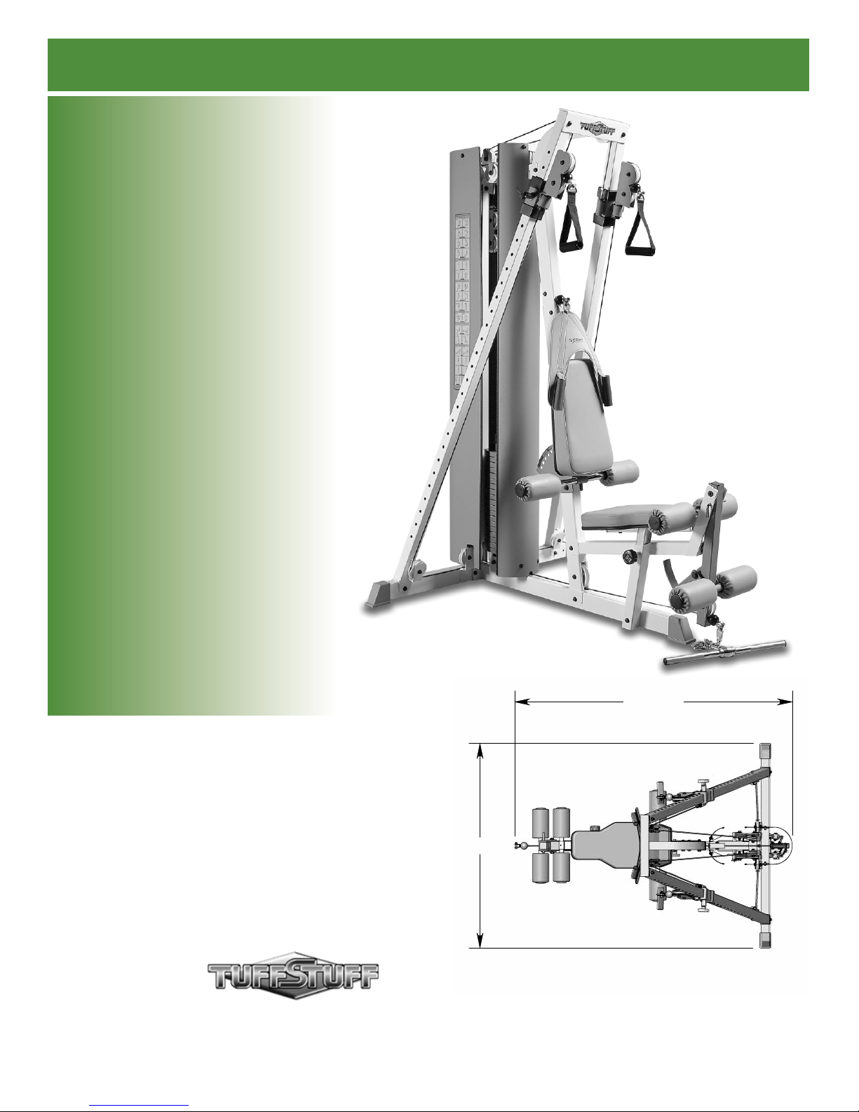
ACS-100
Free Movement Adjustable
Cable System
Revision Date 05-26-04
68 3/4"
51"
America’s Premier Exercise Equipment
© 2003 TASK INDUSTRIES, INC.
L 68 3/4" W 51" H 84 1/2"
ACS-100 Rev0
Page 2
About the Free Movement Adjustable Cable System
S
C
R
E
W
W
I
D
T
H
W
A
S
H
E
R
D
I
A
M
E
T
E
R
N
U
T
D
I
A
M
E
T
E
R
S
C
R
E
W
L
E
N
G
T
H
Congratulations on your new purchase of the ACS-100. We hope
you are completely satisfi ed with this product and wish you many
years of enjoyment.
Prior to the Assembly of the ACS-100
1. We advise you to consult your local Tuff Stuff retailer if you
should have a question or problem regarding the proper
assembly of this unit.
Tuff Stuff Equipment
This Tuffstuff product has been built to precise quality standards
and has been carefully packaged to ensure that damage will
not occur during shipment. The Home Lifetime Warranty and
signature indicating fi nal inspection has been conducted by our line
foreman, is an expression of our confi dence in the completeness,
the materials, and workmanship of this product.
Warranty
SEE A COPY OF WARRANTY ON BACK PAGE.
Registration Card
To avoid unnecessary delays in warranty service and to insure that
a permanent record of your purchase is on fi le with our factory, be
sure to complete the warranty registration card and send it to Task
Industries today.
Specifi cations
1. Maximum Wt. Capacity - 200 lbs.
2. Total Machine Weight - 450.
3. Footprint (LWH) - See Front Cover.
Note: Due to continuing product improvements, specifi cations and designs are subject to change
without notice.
2. Neatly organize and identify all parts according to the Parts List
and the Exploded View Diagram.
Tool Requirements
1. One 3/4” combination wrench
2. Two 9/16” ratchet box wrenches
3. One ratchet
4. One 3/4” socket
5. One 9/16” socket
6. One 7/16” socket
7. One adjustable wrench
8. One rubber mallet
9. Windex or household glass cleaner
10. Measuring tape
11. Utility knife
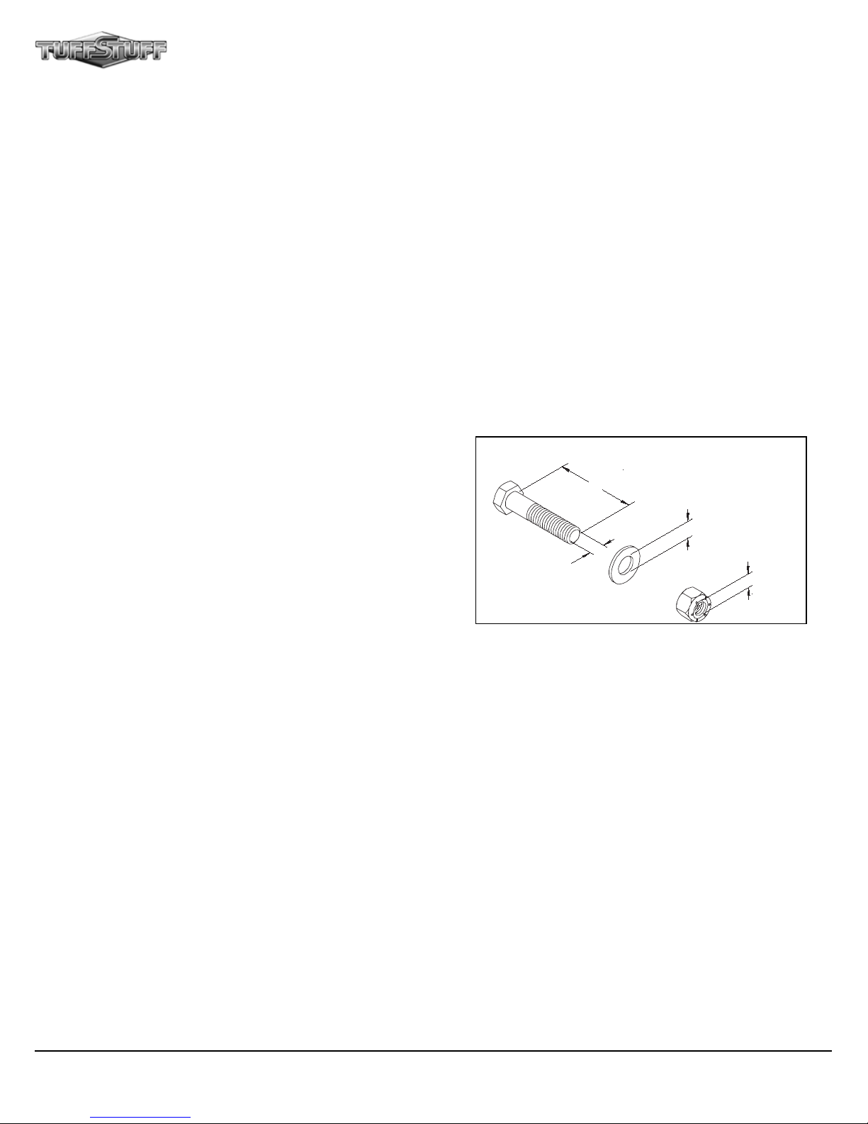
Hardware Measurement Diagram
Safety Precautions
Safety First
Regardless of how enthusiastic you may be about getting on
your equipment and exercising, take the time to ensure that your
safety is not jeopardized. A moment’s lack of attention can result
in an accident, as can failure to observe certain simple safety
precautions.
1. Read, study and understand the Assembly Manual and all the
warning labels on this product. Furthermore, it is recommended
to familiarize yourself and others with the proper operation and
workout recommendations for this Tuff Stuff product prior to
use. Some of this information can be obtained in this Assembly
Manual, as-well-as from your local Tuff Stuff retailer.
2. It is imperative that you retain this Assembly Manual and be
sure all warning labels are legible and intact. Replacement
Assembly Manual and labels are available from your local Tuff
Stuff retailer.
1
3. Consult with your physician before beginning any exercise
program.
4. Use proper discretion when children are present.
5. Frayed or worn cables can be dangerous and may cause injury.
Periodically check the cable for any indication of wear.
6. Keep hands, limbs, loose clothing and long hair well out of the
way of moving parts.
7. Do not attempt to lift more weight than you can control safely.
8. Inspect the Unit for any sign of wear on parts, hardware
becoming loose or cracks on welds. If a problem is found do
not use or allow the machine to be used until the defective
part is repaired or replaced.
ACS-100 Free Movement Adjustable Cable System
Page 3

Assembly Manual
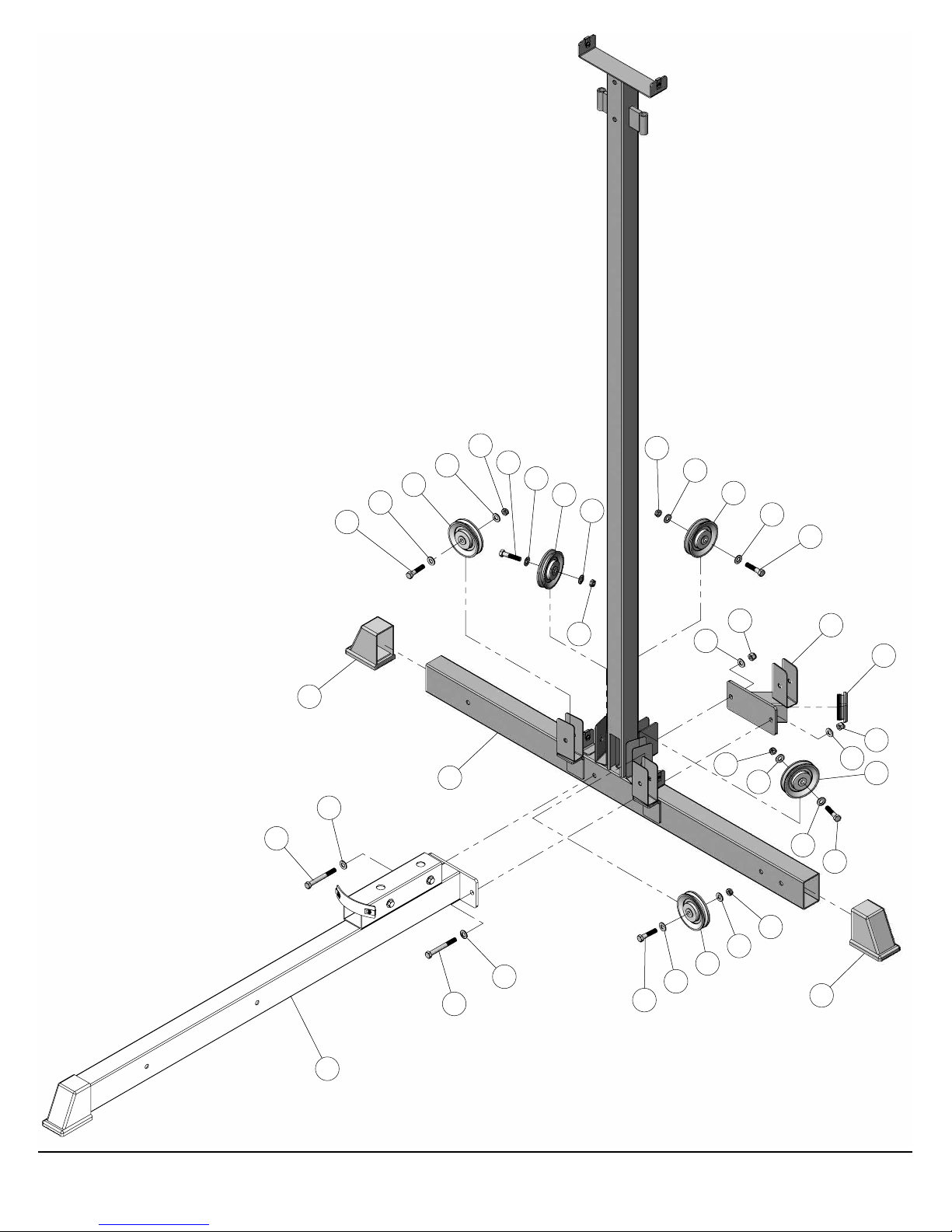
Step 1 Base Frame Assembly
A. Using a rubber mallet, insert one Plastic End Cap 2 X 3 (#73) onto the tube-end of the Base Frame (#1).
B. Assemble two Hex Head Cap Screws 3/8-16 X 2 3/4 (#54) to the Base Frame (#1) using four Flat Washers SAE
3/8” (#44), and two Nylon Insert Jam Lock Nuts 3/8-16 (#69).
Note: Use the overhead view on the cover page for designing your layout before assembling.
Assembly List
Item # Description Qty.
1 BASE FRAME 1
44 FLAT WASHER SAE B/O 3/8” 4
54 HEX HEAD CAP SCREW GR-5 B/O 3/8-16 X 2 3/4 2
69 NYLON INSERT JAM LOCK NUT B/O 3/8-16 2
73 PLASTIC END CAP W/GROOVE 3 X 2 1
73
69 44
44
44
5444
1
ACS-100 Free Movement Adjustable Cable System
2
Page 4

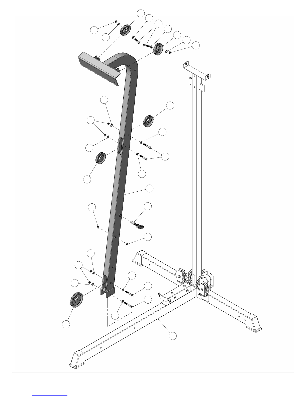
Step 2 Assembling Rear Frame and Bottom Support Pulley Brkt to Base Frame
A. Using a rubber mallet, insert two Plastic End Caps 2 X 3 (#73) onto the tube-ends of the Rear Frame (#5).
B. Assemble Rear Frame (#5) and Bottom Support Pulley Brkt (#18) to Base Frame (#1) using two Hex Head
Cap Screws 3/8-16 X 3 1/4 (#56), four Flat Washers SAE 3/8” (#44), and two Nylon Insert Lock Nuts 3/8-16
(#66).
C. Assemble fi ve Nylon Pulleys 3 1/2 Rd. (#71) to the pulley brackets of the Rear Frame (#5) using hardware
shown.
Assembly List
Item # Description Qty.
5 REAR FRAME 1
18 BOTTOM SUPPORT PULLEY BRKT 1
44 FLAT WASHER SAE B/O 3/8” 14
50 HEX HEAD CAP SCREW GR-5 B/O 3/8-16 X 1 3/4 5
56 HEX HEAD CAP SCREW GR-5 B/O 3/8-16 X 3 1/4 2
66 NYLON INSERT LOCK NUT B/O 3/8-16 2
69 NYLON INSERT JAM LOCK NUT B/O 3/8-16 5
71 NYLON PULLEY 3 1/2 RD, WHITE 5
73 PLASTIC END CAP W/GROOVE 3 X 2 GREY 2
76 PLASTIC INSERT CAP 2” SQ 1
3
ACS-100 Free Movement Adjustable Cable System
Page 5
Assembly Manual
56
73
44
50
44
71
44
69
50
44
71
44
69
5
69
44
44
69
71
66
44
44
50
18
76
66
44
71
44
50
1
ACS-100 Free Movement Adjustable Cable System
56
44
50
69
44
71
44
73
4
Page 6

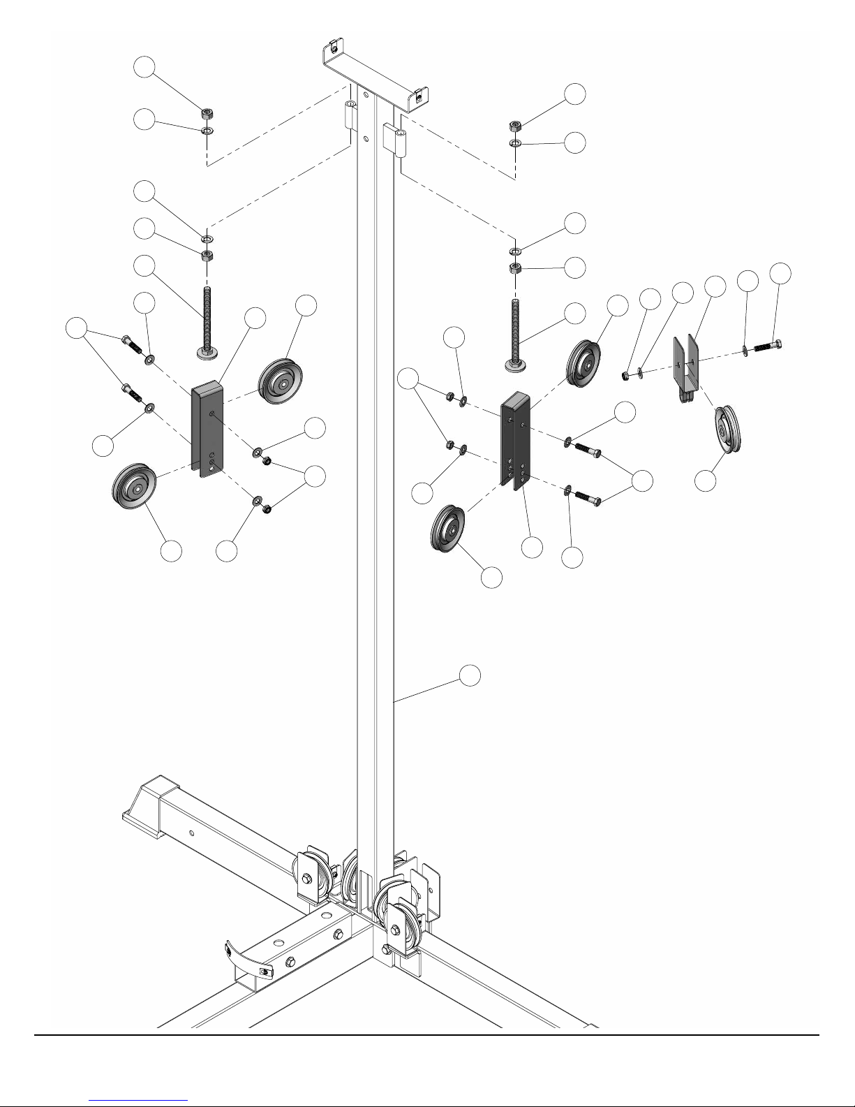
Step 3 Assembly of the Adjustable Stoppers and the Floating Pulley Brackets
A. Install the two Adjustable Stoppers (#21) to the Rear Frame (#5) using hardware shown.
B. Assemble the two Closed End Adjustable Pulley Brkts (#24) and the Floating Pulley Bracket (#22) using
hardware shown
Assembly List
Item # Description Qty.
21 ADJUSTABLE STOPPER 2
22 FLOATING PULLEY BRACKET 1
24 CLOSED END ADJUSTABLE PULLEY BRKT 2
41 FINISHED HEX NUT B/O 1/2-13 4
44 FLAT WASHER SAE B/O 3/8” 10
50 HEX HEAD CAP SCREW GR-5 B/O 3/8-16 X 1 3/4 5
69 NYLON INSERT JAM LOCK NUT B/O 3/8-16 5
71 NYLON PULLEY 3 1/2 RD, WHITE 5
92 SPLIT LOCK WASHER B/O 1/2” 4
5
ACS-100 Free Movement Adjustable Cable System
Page 7
41
92
92
Assembly Manual
41
92
50
44
41
21
44
71 44
24
71
44
69
69
44
44
71
24
44
92
41
21
71
44
50
69
44
71
22
44
50
ACS-100 Free Movement Adjustable Cable System
5
6
Page 8

Step 4 Assembling the Front Frame to the Base Frame
A. Attach the Front Frame (#2) to the Base Frame (#1) using one Hex Head Cap Screw 3/8-16 X 2 3/4 (#54), two
Flat Washers SAE 3/8” (#44), and one Nylon Insert Jam Lock Nut 3/8-16 (#69).
B. Attach one Nylon Pulley 4 1/2 Rd. (#70) to the bottom pulley bracket of the Front Frame (#2) using hardware
shown.
C. Attach four Nylon Pulleys 3 1/2 Rd. (#71) to the pulley brackets of the Front Frame (#2) using hardware
shown.
Assembly List
Item # Description Qty.
2 FRONT FRAME 1
39 BRONZE BUSHING 3/8 X 1/2 X 1/2 X 11/16 X 1/16 2
44 FLAT WASHER SAE B/O 3/8” 12
50 HEX HEAD CAP SCREW GR-5 B/O 3/8-16 X 1 3/4 2
52 HEX HEAD CAP SCREW GR-5 B/O 3/8-16 X 2 1/2 3
54 HEX HEAD CAP SCREW GR-5 B/O 3/8-16 X 2 3/4 1
69 NYLON INSERT JAM LOCK NUT B/O 3/8-16 6
70 NYLON PULLEY 4 1/2 RD, WHITE 1
71 NYLON PULLEY 3 1/2 RD, WHITE 4
80 PUSH PULL PIN 1/2 X 3 1/2 REGULAR 1
7
ACS-100 Free Movement Adjustable Cable System
Page 9
44
69
69
44
44
71
44
Assembly Manual
50
44
71
44
69
71
44
52
44
69
71
44
39
44
2
80
39
44
52
54
44
70
ACS-100 Free Movement Adjustable Cable System
1
8
Page 10

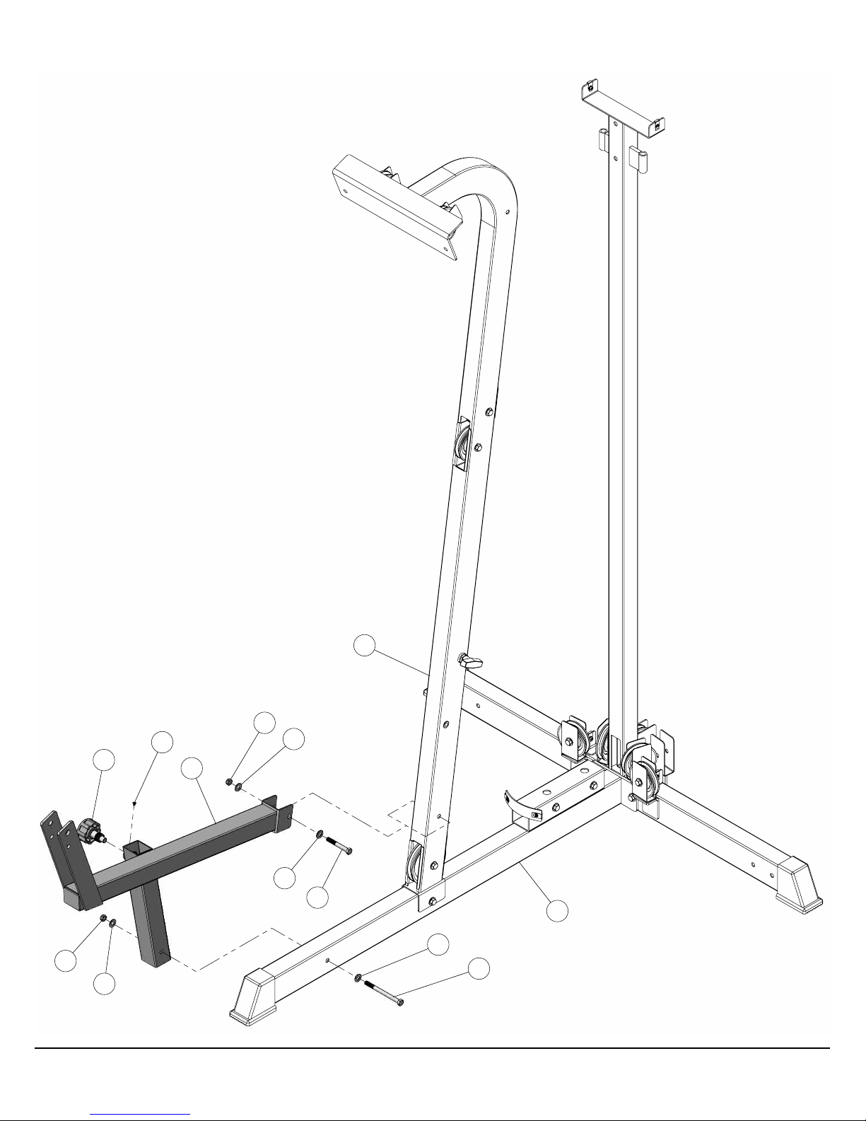
Step 5 Assembling the Bench Frame to the Base Frame and Front Frame
A. Attach the Bench Frame (#9) to the Base Frame (#1) using one Hex Head Cap Screw 3/8-16 X 4 1/2 (#57),
two Flat Washers SAE 3/8” (#44), and one Nylon Insert Jam Lock Nut 3/8-16 (#69).
B. Attach the Bench Frame (#9) to the Front Frame (#2) using one Hex Head Cap Screw 3/8-16 X 2 3/4 (#54),
two Flat Washers SAE 3/8” (#44), and one Nylon Insert Jam Lock Nut 3/8-16 (#69).
Assembly List
Item # Description Qty.
9 LEG EXTENSION BENCH FRAME 1
42 FLAT PHILLIPS MACHINE SCREW 8-32 X 1/4 1
44 FLAT WASHER SAE B/O 3/8” 4
54 HEX HEAD CAP SCREW GR-5 B/O 3/8-16 X 2 3/4 1
57 HEX HEAD CAP SCREW GR-5 B/O 3/8-16 X 4 1/2 1
69 NYLON INSERT JAM LOCK NUT B/O 3/8-16 2
96 TURN/PULL PIN W/KNOB AND LOCK 1
9
ACS-100 Free Movement Adjustable Cable System
Page 11
Assembly Manual
69
96
44
42
2
69
44
9
44
54
1
44
57
ACS-100 Free Movement Adjustable Cable System
10
Page 12

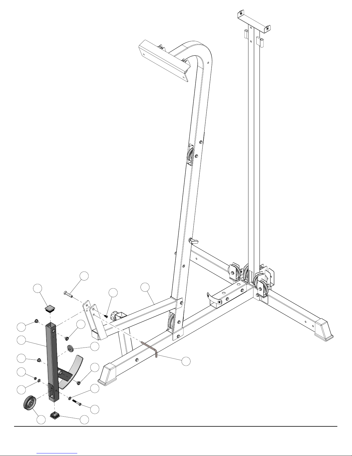
Step 6 Assembling the Leg Extension Arm to the Bench Frame
A. Using a rubber mallet, insert two Plastic Insert Caps 1 3/4 Sq. (#74) into the tube-ends of the Leg Extension
Arm (#11).
B. Attach the Leg Extension Arm (#11) to the Bench Frame (#9) using the Sex Bolt Female 1/2 X 2 5/16 (#86)
and the Sex Bolt Male 5/16-20 X 3/4 (#87).
C. Attach a Nylon Pulley 3 1/2 Rd. (#71) to the Leg Extension Arm (#11) using hardware shown.
Assembly List
Item # Description Qty.
11 LEG EXTENSION ARM 1
38 BRONZE BUSHING 1/2 X 5/8 X 1/2 X 7/8 X 1/8 4
44 FLAT WASHER SAE B/O 3/8” 2
53 HEX HEAD CAP SCREW GR-5 B/O 3/8-16 X 2 1/4 1
60 L-LOCKING PIN 1
69 NYLON INSERT JAM LOCK NUT B/O 3/8-16 1
71 NYLON PULLEY 3 1/2 RD, WHITE 1
74 PLASTIC INSERT CAP 1 3/4” SQ. 10-14 GA. 2
86 SEX BOLT FEMALE 1/2 X 2 5/16 1
87 SEX BOLT MALE 5/16-20 X 3/4 1
97 URETHANE BUMPER 1 3/4 1
11
ACS-100 Free Movement Adjustable Cable System
Page 13
Assembly Manual
86
9
38
11
38
69
44
74
71
87
38
97
38
44
53
74
ACS-100 Free Movement Adjustable Cable System
60
12
Page 14

Step 7 Weight Stack Assembly
A. Attach a Nylon Pulley 4 1/2 Rd. (#70) to the Top Plate Pulley Bracket (#23) using hardware shown.
B. Attach the Selector Pin W/Coil (#28) to the Selector Bar (#34). Then, affi x the Assembled Top Plate Pulley
Bracket (#23) to the Top Plate Selector Bar (#34) using one Finished Hex Nut 1/2-13 (#41), and one Split Lock
Washer 1/2” (#92).
C. Insert the Guide Rods (#8) into the receptacles of the Base Frame (#1).
D. Slide the Rubber Donuts (#83) onto the Guide Rods (#8).
E. Carefully begin sliding the Weight Plates (#33) over the Guide Rods (#8).
F. Slide the Top Plate Selector Bar (#34) onto the Guide Rods (#8) allowing it to rest on top of the completed
Weight Stack.
G. Adhere the Decal Weight Numbers (#107) to the Weight Plates (#33) in the corresponding order. Begin with the
20 at the top, 30 next, and so on.
Assembly List
Item # Description Qty.
8 CHROME SOLID GUIDE ROD 3/4 X 72 2
23 TOP PLATE PULLEY BRACKET 1
28 SELECTOR PIN W/COIL 3/8 X 3 1/2 GOLD KNOB 1
33 10 LB CAST WEIGHT PLATE GREY 19
34 10 LB TOP PLATE/SELECTOR BAR GREY 19 WTS. 1
41 FINISHED HEX NUT B/O 1/2-13 1
44 FLAT WASHER SAE B/O 3/8” 2
51 HEX HEAD CAP SCREW GR-5 B/O 3/8-16 X 2 1
69 NYLON INSERT JAM LOCK NUT B/O 3/8-16 1
70 NYLON PULLEY 4 1/2 RD, WHITE 1
83 RUBBER DONUT 3/4 X 2 1/2 2
92 SPLIT LOCK WASHER B/O 1/2” 1
107 DECAL-NUMBERS 20-200 LBS. SET 1
13
ACS-100 Free Movement Adjustable Cable System
Page 15

51
70
Assembly Manual
44
44
69
41
34
23
92
28
88
33
107
ACS-100 Free Movement Adjustable Cable System
83
83
1
14
Page 16

Step 8 Assembly of the Guide Rod Retainer and the Top Support Pulley Bracket
A. Maneuver the two Guide Rods (#8) into the holes on the bottom side of the Guide Rod Retainer (#14).
B. Attach the Guide Rod Retainer (#14) to the Rear Frame (#5) and the Top Support Pulley Bracket (#17) using
two Hex Head Cap Screws 3/8-16 X 3 1/4 (#56), four Flat Washers SAE 3/8” (#44), and two Nylon Insert Lock
Nuts 3/8-16 (#66).
C. Attach the Guide Rod Retainer (#14) to the Front Frame (#5) using one Hex Head Cap Screw 3/8-16 X 2 3/4
(#54), two Flat Washers SAE 3/8” (#44), and one Nylon Insert Jam Lock Nut 3/8-16 (#69).
D. Making sure that the Cable Retainers (#25) point toward shown direction, install ten Nylon Pulleys 3 1/2 Rd.
(#71) to the Guide Rod Retainer (#14) and the Top Support Pulley Bracket (#17) using hardware shown.
Assembly List
Item # Description Qty.
14 GUIDE ROD RETAINER 1
17 TOP SUPPORT PULLEY BRACKET 1
25 CABLE RETAINER BRACKET 8
44 FLAT WASHER SAE B/O 3/8” 26
50 HEX HEAD CAP SCREW GR-5 B/O 3/8-16 X 1 3/4 6
51 HEX HEAD CAP SCREW GR-5 B/O 3/8-16 X 2 4
54 HEX HEAD CAP SCREW GR-5 B/O 3/8-16 X 2 3/4 1
56 HEX HEAD CAP SCREW GR-5 B/O 3/8-16 X 3 1/4 2
66 NYLON INSERT LOCK NUT B/O 3/8-16 2
69 NYLON INSERT JAM LOCK NUT B/O 3/8-16 11
71 NYLON PULLEY 3 1/2 RD, WHITE 10
85 RUBBER GROMMET 3/4” ID (2867-012) 2
15
ACS-100 Free Movement Adjustable Cable System
Page 17

51
44
25
50
44
25
71
71
44
44
69
44
69
44
50
66
44
44
25
71
Assembly Manual
56
44
69
44
69
71
56
44
44
50
17
51
44
25
69
71
44
69
44
44
54
85
44
85
69
50
69
71
66
44
25
44
44
14
51
71
71
25
25
44
44
50
51
69
44
71
25
44
50
ACS-100 Free Movement Adjustable Cable System
882
5
16
Page 18

Step 9 Assembly of the Selectorized Uprights
A. Insert the Assembled Carriages (#15) onto the Selectorized Uprights (#6 & #7) as shown.
B. Assemble the Selectorized Uprights (#6 & #7) to the Rear Frame (#5) and the Front Frame (#2) using
hardware shown.
C. Install two Nylon Pulleys 3 1/2 Rd. (#71) to the pulley brackets of the Selectorized Uprights (#6 & #7) using
two Hex Head Cap Screws 3/8-16 X 1 3/4 (#50), two Split Lock Washers 3/8” (#93), and two Flat Washers SAE
3/8” (#44).
D. Install four Nylon Pulleys 3 1/2 Rd. (#71) to the High/Low Pulley Brackets (#16) using four Hex Head Cap
Screws 3/8-16 X 1 3/4 (#50), eight Flat Washers SAE 3/8” (#44), and four Nylon Insert Jam Lock Nuts 3/8-16
(#69).
Assembly List
Item # Description Qty.
6 SELECTORIZED UPRIGHT RT 1
7 SELECTORIZED UPRIGHT LT 1
15 CARRIAGE 2
16 HIGH/LOW DOUBLE PULLEY BRKT 2
37 BRONZE BUSHING 1 X 1 1/4 X 3/4 X 1 1/2 X 1/8 4
44 FLAT WASHER SAE B/O 3/8” 18
50 HEX HEAD CAP SCREW GR-5 B/O 3/8-16 X 1 3/4 6
54 HEX HEAD CAP SCREW GR-5 B/O 3/8-16 X 2 3/4 2
55 HEX HEAD CAP SCREW GR-5 B/O 3/8-16 X 3 2
66 NYLON INSERT LOCK NUT B/O 3/8-16 2
69 NYLON INSERT JAM LOCK NUT B/O 3/8-16 6
71 NYLON PULLEY 3 1/2 RD, WHITE 6
77 PLASTIC TUBE END 1 X 1 1/4 X 3/8 2
78 PLASTIC TUBE GUIDE W/LIP-TEETH 2 1/2” SQ. 4
79 PUSH PULL PIN 1/2 X 2 7/8 LIGHT SPRING 2
81 RETAINING SNAP RING EXT. PLAIN .925 X 1 X .042 2
93 SPLIT LOCK WASHER B/O 3/8” 2
17
ACS-100 Free Movement Adjustable Cable System
Page 19

66
44
71
16
78
44
15
44
79
50
69
44
44
37
71
37
Assembly Manual
78
69
77
81
71
7
44
44
93
44
54
50
66
44
55
44
55
44
71
16
5
15
78
2
37
81
78
77
69
44
445493
44
50
79
69
44
69
44
37
71
ACS-100 Free Movement Adjustable Cable System
6
71
44
50
18
Page 20

Step 10 Routing of the Leg Extension / Abdominal Cable (Left Side View)
A1
A. Route the Leg Extension / Abdominal Cable (#30) under Nylon Pulleys Labeled
A2
,
route up to the Top Support Pulley Bracket (#17) passing over the Nylon Pulley 3 1/2 Rd. (#71-Labeled
and under the Cable Retainer (#25).
B. Locate one of the assembled Closed End Adjustable Pulley Brkts (#24) and route the cable under the Nylon
Pulley 3 1/2 Rd. (#71-Labeled
Pulleys 3 1/2 Rd. (#71-Labeled
A5
). Next, route up to the Guide Rod Retainer (#14) passing over the Nylon
&
A7
) and under the Cable Retainers (#25).
A6
C. Route the cable down to the Top Plate Pulley Bracket (#23) and route it under the Nylon Pulley 4 1/2 Rd.
(#70-Labeled
Labeled
A9
). Then, up to the Guide Rod Retainer (#14) passing over the Nylon Pulleys 3 1/2 Rd. (#71-
A8
A10
&
) and under the Cable Retainers (#25).
D. Locate the other assembled Closed End Adjustable Pulley Brkt (#24) and route the cable under the Nylon
Pulley 3 1/2 Rd. (#71-Labeled
Nylon Pulley 3 1/2 Rd. (#71-Labeled
A11
). Next, route up to the Top Support Pulley Bracket (#17) passing over the
A12
) and under the Cable Retainer (#25).
E. Locate the Floating Pulley Bracket (#22) and route the cable under the Nylon Pulley 3 1/2 Rd.
(#71-Labeled
3 1/2 Rd. (#71-Labeled
). Next, route up to the Top Support Pulley Bracket (#17) passing over the Nylon Pulley
A13
).
A14
&
A3
). Next,
A4
)
F. Route the cable to the Nylon Pulley 3 1/2 Rd. (#71-Labeled
Rd. (#71-Labeled
) passing over the Nylon Pulley 3 1/2 Rd. (#71-Labeled
A16
). Next, route down to the Nylon Pulley 3 1/2
A15
).
A17
G. Assemble the Abdominal Crunch Harness (#35) to the Cable-end using hardware shown. Affi x the Nylon Ball
w/Threaded Socket to the Cable (#30) by threading the Socket Set Screw 3/8-16 X 3/4 (#110).
H. Assemble the Low Row Bar (#61) to the Cable (#30) using hardware shown.
Assembly List
Item # Description Qty.
30 LEG EXTENSION / ABDONIMAL CABLE 1
35 ABDOMINAL CRUNCH HARNESS 1
61 LOW ROW BAR 20” 1
63 NYLON BALL 1 3/4 X 5/16 1
67 NYLON INSERT LOCK NUT B/O 5/16-18 2
84 RUBBER GRIP 1 X 6 1/4 2
88 SHOULDER BOLT ALLOY 3/8 X 3/4 2
89 SNAP LINK Z/P 8MM X 80MM 3
95 STRAP BRACKET 20 #SF20 STAINLESS STEEL 2
99 COIL CHAIN Z/P 3/16 X 21 1
109 NYLON BALL W/THREADED SOCKET 1 3/4 X 5/16 1
110 SOCKET SET SCREW 3/8-16 X 3/4 1
19
ACS-100 Free Movement Adjustable Cable System
Page 21

Assembly Manual
Step 10 Routing of the Leg Extension / Abdominal Cable (Right Side View)
A1
A. Route the Leg Extension / Abdominal Cable (#30) under Nylon Pulleys Labeled
A2
,
route up to the Top Support Pulley Bracket (#17) passing over the Nylon Pulley 3 1/2 Rd. (#71-Labeled
and under the Cable Retainer (#25).
B. Locate one of the assembled Closed End Adjustable Pulley Brkts (#24) and route the cable under the Nylon
Pulley 3 1/2 Rd. (#71-Labeled
Pulleys 3 1/2 Rd. (#71-Labeled
A5
). Next, route up to the Guide Rod Retainer (#14) passing over the Nylon
&
A7
) and under the Cable Retainers (#25).
A6
C. Route the cable down to the Top Plate Pulley Bracket (#23) and route it under the Nylon Pulley 4 1/2 Rd.
(#70-Labeled
Labeled
A9
). Then, up to the Guide Rod Retainer (#14) passing over the Nylon Pulleys 3 1/2 Rd. (#71-
A8
A10
&
) and under the Cable Retainers (#25).
D. Locate the other assembled Closed End Adjustable Pulley Brkt (#24) and route the cable under the Nylon
Pulley 3 1/2 Rd. (#71-Labeled
Nylon Pulley 3 1/2 Rd. (#71-Labeled
A11
). Next, route up to the Top Support Pulley Bracket (#17) passing over the
A12
) and under the Cable Retainer (#25).
E. Locate the Floating Pulley Bracket (#22) and route the cable under the Nylon Pulley 3 1/2 Rd.
(#71-Labeled
3 1/2 Rd. (#71-Labeled
). Next, route up to the Top Support Pulley Bracket (#17) passing over the Nylon Pulley
A13
).
A14
&
A3
). Next,
A4
)
F. Route the cable to the Nylon Pulley 3 1/2 Rd. (#71-Labeled
Rd. (#71-Labeled
) passing over the Nylon Pulley 3 1/2 Rd. (#71-Labeled
A16
). Next, route down to the Nylon Pulley 3 1/2
A15
).
A17
G. Assemble the Abdominal Crunch Harness (#35) to the Cable-end using hardware shown. Affi x the Nylon Ball
w/Threaded Socket to the Cable (#30) by threading the Socket Set Screw 3/8-16 X 3/4 (#110).
H. Assemble the Low Row Bar (#61) to the Cable (#30) using hardware shown.
Assembly List
Item # Description Qty.
30 LEG EXTENSION / ABDONIMAL CABLE 1
35 ABDOMINAL CRUNCH HARNESS 1
61 LOW ROW BAR 20” 1
63 NYLON BALL 1 3/4 X 5/16 1
67 NYLON INSERT LOCK NUT B/O 5/16-18 2
84 RUBBER GRIP 1 X 6 1/4 2
88 SHOULDER BOLT ALLOY 3/8 X 3/4 2
89 SNAP LINK Z/P 8MM X 80MM 3
95 STRAP BRACKET 20 #SF20 STAINLESS STEEL 2
99 COIL CHAIN Z/P 3/16 X 21 1
109 NYLON BALL W/THREADED SOCKET 1 3/4 X 5/16 1
110 SOCKET SET SCREW 3/8-16 X 3/4 1
ACS-100 Free Movement Adjustable Cable System
22
Page 22

Step 11 Routing one of the Crossover Cables to the Left Side of the Unit
A. Route the Crossover Cable (#29) between Nylon Pulleys (#71-Labeled
B1
tube of the High/Low Double Pulley Brkt (#16) and down to the Nylon Pulley (#71-Labeled
B. Route the cable under the Nylon Pulley (#71-Labeled
(#24) and route the cable over the Nylon Pulley (#71-Labeled
Pulley (#71-Labeled
B6
).
B4
) then up to the Closed End Adjustable Pulley Brkt
B5
). Next, route down and under the Nylon
C. Route up to the Guide Rod Retainer (#14) passing over the Nylon Pulley (#71-Labeled
Cable Retainer (#25). Next, route over the Nylon Pulley (#71-Labeled
B8
B2
&
). Next, route through the
B3
).
B7
) and under the
).
D. Route the cable to the threaded socket of the Carriage (#15). Secure the Cable (#29) to the Carriage (#15)
using one Split Hex Tap Bolt 1/2-13 X 3 1/2 (#91), one Finished Hex Nut 1/2-13 (#41), and one Split Washer
1/2” (#92).
E. Assemble one of the Nylon D Handles (#64) to the Cable (#29) using hardware shown.
Assembly List
Item # Description Qty.
29 CROSSOVER CABLE 1
41 FINISHED HEX NUT B/O 1/2-13 1
63 NYLON BALL 1 3/4 X 5/16 1
64 NYLON D HANDLE (# H834A) 1
67 NYLON INSERT LOCK NUT B/O 5/16-18 1
88 SHOULDER BOLT ALLOY 3/8 X 3/4 1
91 SPLIT HEX TAP BOLT GR-5 B/O 1/2-13 X 3 1/2 1
92 SPLIT LOCK WASHER B/O 1/2” 1
95 STRAP BRACKET 20 #SF20 STAINLESS STEEL 1
23
ACS-100 Free Movement Adjustable Cable System
Page 23

Assembly Manual
2
B7
25
View from Opposite Side
91
29
41
92
15
64
67
95
B8
63
B1
29
24
14
B5
B2
16
64
ACS-100 Free Movement Adjustable Cable System
7
88
B6
B3
B4
5
24
Page 24

Step 12 Routing of the other Crossover Cable to the Right Side of the Unit
A. Route the Crossover Cable (#29) between Nylon Pulleys (#71-Labeled
C1
tube of the High/Low Double Pulley Brkt (#16) and down to the Nylon Pulley (#71-Labeled
B. Route the cable under the Nylon Pulley (#71-Labeled
(#24) and route the cable over the Nylon Pulley (#71-Labeled
Pulley (#71-Labeled
C6
).
C4
) then up to the Closed End Adjustable Pulley Brkt
C5
). Next, route down and under the Nylon
C. Route up to the Guide Rod Retainer (#14) passing over the Nylon Pulley (#71-Labeled
Cable Retainer (#25). Next, route over the Nylon Pulley (#71-Labeled
C8
C2
&
). Next, route through the
C3
).
C7
) and under the
).
D. Route the cable to the threaded socket of the Carriage (#15). Secure the Cable (#29) to the Carriage (#15)
using one Split Hex Tap Bolt 1/2-13 X 3 1/2 (#91), one Finished Hex Nut 1/2-13 (#41), and one Split Washer
1/2” (#92).
E. Assemble the other Nylon D Handle (#64) to the Cable (#29) using hardware shown.
Assembly List
Item # Description Qty.
29 CROSSOVER CABLE 1
41 FINISHED HEX NUT B/O 1/2-13 1
63 NYLON BALL 1 3/4 X 5/16 1
64 NYLON D HANDLE (# H834A) 1
67 NYLON INSERT LOCK NUT B/O 5/16-18 1
88 SHOULDER BOLT ALLOY 3/8 X 3/4 1
91 SPLIT HEX TAP BOLT GR-5 B/O 1/2-13 X 3 1/2 1
92 SPLIT LOCK WASHER B/O 1/2” 1
95 STRAP BRACKET 20 #SF20 STAINLESS STEEL 1
25
ACS-100 Free Movement Adjustable Cable System
Page 25

Assembly Manual
24
C5
C7
14
C1
225
View from Opposite Side
C8
91
29
41
92
15
64
C3
C2
16
6
29
63
95
67
64
88
C6
C4
5
ACS-100 Free Movement Adjustable Cable System
26
Page 26

Step 13 Routing of the Tension Cable
A. Attach the Tension Cable (#31) to the Floating Pulley Bracket (#22) and secure it into place using one
shoulder Bolt 3/8 X 3/4 (#88) and one Nylon Insert Lock Nut 5/16-18 (#67).
B. Route the Cable down and secure it to the Bottom Support Pulley Brkt (#18) using one Hex Head Cap Screw
3/8-16 X 1 3/4 (#50), two Flat Washers SAE 3/8” (#44), two Nylon Spacers 3/8 X 3/4 X 3/8 (#72), and one Nylon
Insert Jam Lock Nut 3/8-16 (#69).
Assembly List
Item # Description Qty.
31 TENSION CABLE 1
44 FLAT WASHER SAE B/O 3/8” 2
50 HEX HEAD CAP SCREW GR-5 B/O 3/8-16 X 1 3/4 1
67 NYLON INSERT LOCK NUT B/O 5/16-18 1
69 NYLON INSERT JAM LOCK NUT B/O 3/8-16 1
72 NYLON SPACER 3/8 X 3/4 X 3/8 2
88 SHOULDER BOLT ALLOY 3/8 X 3/4 1
27
ACS-100 Free Movement Adjustable Cable System
Page 27

A13
Assembly Manual
31
69
44
88
18
72
31
31
22
67
72
44
50
ACS-100 Free Movement Adjustable Cable System
5
18
28
Page 28

Step 14 Cable Adjustment
It is imperative that you maintain proper cable adjustment to ensure a safe and smooth operation.
Caution: The cable should be inspected and adjusted periodically to avoid any slack in the cable, which
would, consequently, prevent any damage to the equipment or personal injury.
29
ACS-100 Free Movement Adjustable Cable System
Page 29

Step 14 Cable Adjustment
Assembly Manual
41
41
21
24
21
Adjustment for:
Adjustable Stoppers (#21)
1. Loosen both Finished Hex Nuts (#41).
5
2. Adjust the Adjustable Stopper (#21) to make contact with the
Closed-end Adjustable Pulley Brkt (#24).
3. Re-tighten both Finished Hex Nuts (#41) to complete the
adjustment.
Note: Be sure the Closed-end Adjustable Pulley Brkt (#24)
is making contact with the Adjustable Stopper (#21).
Major Cable Adjustment:
1. Remove the hardware from the Nylon Pulley (#71) located at one of
the three holes on the Closed-end Adjustable Pulley Brkt (#24).
2. By interchanging the Nylon Pulley (#71) within the Closed-end
Adjustable Pulley Brkt (#24) to the next adjustment hole it will
make one-inch cable adjustment
.
24
71
29
91
41
15
3. Re-tighten the hardware for the Nylon Pulley (#71) to complete the
adjustment.
Minor Cable Adjustment:
1. Loosen the Finished Hex Nut (#41).
2. Thread the Split Hex Tap Bolt 1/2-13 X 3 1/2 (#91) in or out of the
threaded socket of the Carriage (#15) to give the cables proper
tension.
3. Re-tighten the Finished Hex Nut (#41) to complete the adjustment.
Caution: Make sure the Split Hex Tap Bolt 1/2-13 X 3
1/2 (#91) is threaded at least 1/2” into the threaded socket
of the Carriage (#15) once the cable adjustment has been
completed.
ACS-100 Free Movement Adjustable Cable System
30
Page 30

Step 15 Weight Shields Assembly
A. Attach the Front Weight Shield (#20) to the Base Frame (#1) and the Guide Rod Retainer (#14) using four
Hex Head Cap Screws 1/4-20 X 3/4 (#48), and four Flat Washers USS 1/4” (#45).
B. Attach the Rear Weight Shield (#19) to the Rear Frame (#5) using four Hex Head Cap Screws 1/4-20 X 3/4
(#48), and four Flat Washers USS 1/4” (#45).
Assembly List
Item # Description Qty.
19 WEIGHT SHIELD REAR 1
20 WEIGHT SHIELD FRONT 1
40 EDGE PROTECTOR BLACK 1/16 4
45 FLAT WASHER USS B/O 1/4” 8
48 HEX HEAD CAP SCREW GR-5 B/O 1/4-20 X 3/4 8
31
ACS-100 Free Movement Adjustable Cable System
Page 31

Assembly Manual
48
48
45
45
14
40
40
48
45
45
48
19
45
20
40 40
48
45
45
48
1
5
4548
ACS-100 Free Movement Adjustable Cable System
32
Page 32

Step 16 Back Pad Assembly
A. Attach the Back Pad Adjustable Bracket (#3) to the Front Frame (#2) using one Hex Head Cap Screw 3/8-16
X 3 1/4 (#56), two Flat Washers SAE 3/8” (#44), two Nylon Flat Washers 3/8” (#65), and one Nylon Insert Jam
Lock Nut 3/8-16 (#69).
B. Attach two Metal Hinges (#62) to the Back Pad Adjustable Bracket (#3). Then, attach the Back Pad (#27) to
the Metal Hinges (#62) using two Hex Head Cap Screws 3/8-16 X 1 1/4 (#49), and two Flat Washers SAE 3/8”
(#44).
C. Attach the Rubber Bumper 3/8 X 1 1/2 (#82) to the Back Pad (#27) using one Hex Head Cap Screw 3/8-16 X
1 1/4 (#49),
D. Insert the Foot Roll Tube 1 X 27 (#4) into the receptacle of the Back Pad Adjustable Bracket (#3). Use a
measuring tape to center the Foot Roll Tube 1 X 27 (#4) to the Back Pad Adjustable Bracket (#3) and secure
it into place using one Socket Set Screw 1/4-20 X 1/4 (#90).
E. Attach two Foam Rolls 1 X 4 X 7 1/4 (#32) and two Foot Roll Plastic End Caps 1” (#46) to the Foot Roll Tube
1 X 27 (#4).
Assembly List
Item # Description Qty.
3 BACK PAD ADJUSTABLE BRACKET 1
4 FOOT ROLL TUBE 1 X 27 1
27 BACK PAD 1
32 FOAM ROLL 1 X 4 X 7 1/4 2
44 FLAT WASHER SAE B/O 3/8” 4
46 FOOT ROLL PLASTIC END CAP 1” 2
49 HEX HEAD CAP SCREW GR-5 B/O 3/8-16 X 1 1/4 3
56 HEX HEAD CAP SCREW GR-5 B/O 3/8-16 X 3 1/4 1
62 METAL HINGE 2
65 NYLON FLAT WASHER 3/8 2
69 NYLON INSERT JAM LOCK NUT B/O 3/8-16 1
82 RUBBER BUMPER 3/8 X 1 1/2 1
90 SOCKET SET SCREW ALLOY 1/4-20 X 1/4 1
33
ACS-100 Free Movement Adjustable Cable System
Page 33

Assembly Manual
49
82
49
44
80
2
39
46
32
4
56
27
ACS-100 Free Movement Adjustable Cable System
62
44
49
62
46
32
90
44
65
3
65
44
69
34
Page 34

Step 17 Seat Pad & Foot Roll Bracket Assembly
A. Using a rubber mallet, insert one Plastic Insert Cap 1 X 2 (#75) into the tube-end of the Adjustable Seat Frame
(#10).
B. Attach the Seat Pad (#26) to the Adjustable Seat Frame (#10) using two Hex Head Cap Screws
3/8-16 X 1 3/4 (#50), and two Flat Washers SAE 3/8” (#44).
C. Insert the Foot Roll Tube 1 X 18 (#12) into the receptacle of the Adjustable Seat Frame (#10). Use a
measuring tape to center the Foot Roll Tube 1 X 18 (#12) to the Adjustable Seat Frame (#10) and secure it
into place using one Socket Set Screw 1/4-20 X 1/4 (#90).
D. Attach the Foot Roll Bracket (#13) to the Leg Extension Arm (#11) using one Hex Head Cap Screw
1/2-13 X 3 1/2 (#47), two Flat Washers SAE 1/2” (#43), and one Nylon Insert Jam Lock Nut 1/2-13 (#68).
E. Attach Foam Rolls 1 X 4 X 7 1/4 (#32) and Foot Roll Plastic End Caps 1” (#46) to the Foot Roll Tube 1 X 18
(#12) and the Foot Roll Bracket (#13).
Assembly List
Item # Description Qty.
10 ADJUSTABLE SEAT FRAME 1
12 FOOT ROLL TUBE 1 X 18 1
13 FOOT ROLL BRACKET 1
26 SEAT PAD 1
32 FOAM ROLL 1 X 4 X 7 1/4 4
43 FLAT WASHER SAE B/O 1/2” 2
44 FLAT WASHER SAE B/O 3/8” 2
46 FOOT ROLL PLASTIC END CAP 1” 4
47 HEX HEAD CAP SCREW GR-5 B/O 1/2-13 X 3 1/2 1
50 HEX HEAD CAP SCREW GR-5 B/O 3/8-16 X 1 3/4 2
68 NYLON INSERT JAM LOCK NUT B/O 1/2-13 1
75 PLASTIC INSERT CAP 1” X 2”_ 10-14 GA. 1
90 SOCKET SET SCREW ALLOY 1/4-20 X 1/4 1
35
ACS-100 Free Movement Adjustable Cable System
Page 35

Assembly Manual
26
12
90
75
10
44
32
46
50
44
50
9
11
4632
47
43
13
43
32
46
ACS-100 Free Movement Adjustable Cable System
68
32
46
36
Page 36

Step 18 Detail assembly inspection
A. Check all hardware assemblies to be fully fastened.
B. Check cables to be properly routed.
C. Test cables to be running smoothly through pulleys using only the weight of the Top Plate.
37
ACS-100 Free Movement Adjustable Cable System
Page 37

Notes
ACS-100 Free Movement Adjustable Cable System
38
Page 38

COLOR CHART
GRAY= SUB-ASSEMBLY PARTS
BLACK= HARDWARE
ACS-100
Parts List
Item No.
1 BASE FRAME UP2810 1 56 HEX HEAD CAP SCREW GR-5 B/O 3/8-16 X 3 1/4 BNH0312 5
2 FRONT FRAME UP2813 1 57 HEX HEAD CAP SCREW GR-5 B/O 3/8-16 X 4 1/2 BNH0284 1
3 BACK PAD ADJUSTABLE BRACKET UP0554 1 58 HEX KEY 1/8" BNH0767 1
4 FOOT ROLL TUBE 1 X 27 UP0743 1 59 HEX KEY 3/16" BNH0371 1
5 REAR FRAME UP2814 1 60 L-LOCKING PIN BNH0045 1
6 SELECTORIZED UPRIGHT RT UP2811 1 61 LOW ROW BAR 20" BNH0294 1
7 SELECTORIZED UPRIGHT LT UP2812 1 62 METAL HINGE BNH0046 2
8 CHROME SOLID GUIDE ROD 3/4 X 72 UP0124 2 63 NYLON BALL 1 3/4 X 5/16 BNH0047 3
9 LEG EXTENSION BENCH FRAME UP2809 1 64 NYLON D HANDLE (# H834A) BNH1215 2
10 ADJUSTABLE SEAT FRAME UP2806 1 65 NYLON FLAT WASHER 3/8 BNH0248 2
11 LEG EXTENSION ARM UP2804 1 66 NYLON INSERT LOCK NUT B/O 3/8-16 BNH0214 6
12 FOOT ROLL TUBE 1 X 18 UP2808 1 67 NYLON INSERT LOCK NUT B/O 5/16-18 BNH0215 5
13 FOOT ROLL BRACKET UP2815 1 68 NYLON INSERT JAM NUT B/O 1/2-13 BNH0366 1
14 GUIDE ROD RETAINER UP2807 1 69 NYLON INSERT JAM LOCK NUT B/O 3/8-16 BNH0365 41
15 CARRIAGE UP2797 2 70 NYLON PULLEY 4 1/2 RD., WHITE BNH0556 2
16 HIGH/LOW DOUBLE PULLEY BRKT UP1023 2 71 NYLON PULLEY 3 1/2 RD., WHITE BNH1136 31
17 TOP SUPPORT PULLEY BRACKET UP2799 1 72 NYLON SPACER 3/8 X 3/4 X 3/8 BNH0392 2
18 BOTTOM SUPPORT PULLEY BRKT UP2805 1 73 PLASTIC END CAP W/GROOVE 3 X 2 GREY BNH0134 3
19 WEIGHT SHIELD, REAR UP2816 1 74 PLASTIC INSERT CAP 1 3/4" SQ. 10-14 GA. BNH0053 2
20 WEIGHT SHIELD, FRONT UP2817 1 75 PLASTIC INSERT CAP 1" X 2"_ 10-14 GA. BNH0005 3
21 ADJUSTABLE STOPPER UP2800 2 76 PLASTIC INSERT CAP 2" SQ BNH0012 1
22 FLOATING PULLEY BRACKET UP2801 1 77 PLASTIC TUBE END 1 X 1 1/4 X 3/8 BNH1089 2
23 TOP PLATE PULLEY BRACKET UP2802 1 78 PLASTIC TUBE GUIDE W/LIP-TEETH 2 1/2" SQ. BNH0060 4
24 CLOSED END ADJUSTABLE PULLEY BKT UP2803 2 79 PUSH PULL PIN 1/2 X 2 7/8 LIGHT SPRING BNH0542 2
25 CABLE RETAINER BRACKET UP0998 8 80 PUSH PULL PIN 1/2 X 3 1/2 REGULAR BNH0520 1
26 SEAT PAD UP0173 1 81 RETAINING SNAP RING EXT. PLAIN .925 X 1 X .042 BNH0419 2
27 BACK PAD UP0370 1 82 RUBBER BUMPER 3/8 X 1 1/2 BNH0514 1
28 SELECTOR PIN W/COIL 3/8 X 3 1/2 GOLD KNOB UP3051 1 83 RUBBER DONUT 3/4 X 2 1/2 BNH0068 2
29 CROSSOVER CABLE UP2819 2 84 RUBBER GRIP 1 X 6 1/4 BNH0296 2
30 LEG EXTENSION / ABDOMINAL CABLE UP2820 1 85 RUBBER GROMMET 3/4" ID (2867-012) BNH0401 2
31 TENSION CABLE UP2818 1 86 SEX BOLT FEMALE 1/2 X 2 5/16 BNH1393 1
32 FOAM ROLL 1 X 4 X 7 1/4 UP0375
33 10 LB CAST WEIGHT PLATE GREY BNH0904 19 88 SHOULDER BOLT ALLOY 3/8 X 3/4 BNH0718 5
34 10 LB TOP PLATE/SELECTOR BAR GREY 19 WTS. BNH0932 1 89 SNAP LINK Z/P 8MM X 80MM BNH0065 3
35 ABDOMINAL CRUNCH HARNESS BNH0235 1 90 SOCKET SET SCREW ALLOY 1/4-20 X 1/4 BNH0790 2
36 ANKLE STRAP BNH1435 1 91 SPLIT HEX TAP BOLT GR-5 B/O 1/2-13 X 3 1/2 BNH1131 2
37 BRONZE BUSHING 1 X 1 1/4 X 3/4 X 1 1/2 X 1/8 BNH0527 4 92 SPLIT LOCK WASHER B/O 1/2" BNH0653 7
38 BRONZE BUSHING 1/2 X 5/8 X 1/2 X 7/8 X 1/8 BNH0528 4 93 SPLIT LOCK WASHER B/O 3/8" BNH0658 2
39 BRONZE BUSHING 3/8 X 1/2 X 1/2 X 11/16 X 1/16 BNH0738 2 94 HEX KEY M8 BNH0571 1
40 EDGE PROTECTOR BLACK 1/16 BNH0587 4 95 STRAP BRACKET 20 #SF20 STAINLESS STEEL BNH0562 4
41 FINISHED HEX NUT B/O 1/2-13 BNH0201 7 96 TURN/PULL PIN W/KNOB AND LOCK BNH0989 1
42 FLAT PHILLIPS MACHINE SCREW 8-32 X 1/4 BNH0408 1 97 URETHANE BUMPER 1 3/4 BNH0229 1
43 FLAT WASHER SAE B/O 1/2" BNH0238 2 98 U-STYLE TAPPED HOLE NUT 1/4-20 BNH0708 8
44 FLAT WASHER SAE B/O 3/8" BNH0239 100 99 COIL CHAIN Z/P 3/16 X 21 BNH1262 1
45 FLAT WASHER USS B/O 1/4" BNH0233 8 100 DECAL-EXERCISE CHART BNH1486 2
46 FOOT ROLL PLASTIC END CAP 1" BNH0397 6 101 DECAL-NUMBERS 1-28 BNH1487 2
47 HEX HEAD CAP SCREW GR-5 B/O 1/2-13 X 3 1/2 BNH0263 1 102 DECAL-ADJUST CABLE HERE BNH0789 4
48 HEX HEAD CAP SCREW GR-5 B/O 1/4-20 X 3/4 BNH0890 8 103 DECAL-CAUTION 1 3/4 X 5 1/2 BNH0126 1
49 HEX HEAD CAP SCREW GR-5 B/O 3/8-16 X 1 1/4 BNH0273 3 104 DECAL-DANGER TIGHTEN THIS RET..., 3/4 X 1 1/2 BNH0142 3
50 HEX HEAD CAP SCREW GR-5 B/O 3/8-16 X 1 3/4 BNH0274 27 105 DECAL-FOR BEST PERFORMANCE 1 1/4 X 1 1/2 BNH0143 1
51 HEX HEAD CAP SCREW GR-5 B/O 3/8-16 X 2 BNH0279 5 106 DECAL-LARGE TUFFSTUFF BNH0360 1
52 HEX HEAD CAP SCREW GR-5 B/O 3/8-16 X 2 1/2 BNH0276 3 107 DECAL-NUMBERS 20-200 LBS. SET BNH0902 1
53 HEX HEAD CAP SCREW GR-5 B/O 3/8-16 X 2 1/4 BNH0277 1 108 DECAL-WARNING KEEP HANDS AND FINGERS.. BNH0620 2
54 HEX HEAD CAP SCREW GR-5 B/O 3/8-16 X 2 3/4 BNH0278 7 109 NYLON BALL W/THREADED SOCKET 1 3/4 X 5/16 BNH0022 1
55 HEX HEAD CAP SCREW GR-5 B/O 3/8-16 X 3 BNH0282 2 110 SOCKET SET SCREW ALLOY 3/8-16 X 3/4 BNH0476 1
Description Part No. Qty
Item No.
6 87 SEX BOLT MALE 5/16-20 X 3/4 BNH1392 1
Description Part No. Qty
39
ACS-100 Free Movement Adjustable Cable System
Page 39

Notes
ACS-100 Free Movement Adjustable Cable System
41
Page 40

ACS-100 Basic Exercise Guide
Lat Pulldown Triceps Extension Triceps Pushdown Pectoral Crossover
Abdominal Crunch Chest Press Incline Press Seated Mid Row
Pectoral Fly Rear Delt Lateral Crossover Lateral Pull-In
Oblique Twist Upright Row Deltoid Raise Standing Arm Curl
42
ACS-100 Free Movement Adjustable Cable System
Page 41

ACS-100 Basic Exercise Guide
Back Kick Inner Thigh Outer Thigh Side Bend
Leg Extension
Standing Leg Curl Leg Press (optional)
Weight Training Safety Tips:
It is important to read all caution and warning labels posted on the
machine. Follow proper safety procedures and rules, and become
familiar with the equipment and adjustments.
Before use, inspect equipment for wear and tear. Walk around the
equipment to look for worn or loose fittings, frayed cables and
dry, unlubricated guide rods.
Before beginning any type of exercise program, it’s important to
consult your physician if you have not been involved in a regular
exercise program, smoke or have signs of high blood pressure.
Always warm-up before and cool-down after weight training.
Warm-up for 10-15 minutes with stretching and cardiovascular
exercises. Cool-down should include light stretching exercises for
5-15 minutes.
Never hold your breath – will limit the flow of oxygen to your
brain and may cause dizziness. The most often used breathing
pattern is inhaling during least resistance and exhaling during
maximum resistance.
The length of rest interval between sets for an average weight
training session should be one minute. More intense and
advanced training session, three minutes between sets.
If you are unfamiliar with the equipment or exercises,
please consult with a certified instructor or TuffStuff Authorized
Dealer to prevent the possibilities of injuries, development of
poor form and bad habits.
Questions or for more information, please contact TuffStuff at
909-629-1600 or email: info@tuffstuff.net.
SUGGESTED EXERCISE PROGRAM
Desired Muscular Results # Sets # Repetitions Intensity
1. For Strength and Size 3 – 5 5 – 8 70% – 80% 1RM*
2. Definition & Muscular Endurance 3 – 5 9 – 15 40% – 70% 1RM*
3. General Fitness & Circuit Weight Training 3 – 5 10 – 15 40% – 70% 1RM*
* 1RM (one repetition maximum) = Maximum amount of weight you can use for one repetition in good form.
A typical order of exercises:
ACS-100 Free Movement Adjustable Cable System
• Abdominals • Thighs • Chest • Back • Shoulders • Triceps • Biceps
43
Page 42

Maintenance
TuffStuff Basic Strength Equipment Safety and General Maintenance
All TUFFSTUFF strength equipment is designed and manufactured to offer maximum, long-life service
with minimal maintenance. However, safety inspection and routine maintenance in your facility should be
the upmost importance in your daily operation. Information presented in these pages will serve as a basic
guideline to design your own inspection procedures.
Part One: General Inspection and Cleaning
Equipment should be wiped down with a damp cloth and dried on a daily basis. The powder coat fi nish
should be polished with a good car wax on a weekly basis. A daily wipe down of the upholstery with a lanolin based hand cleaner or Naugahyde Cleaner. Do not use cleaners such as Lysol or Windex as they will
dry out and crack the vinyl. Lanolin hand cleaner dissolves the sweat and lubricates the vinyl, maintaining
its natural fl exibility. Sweat is corrosive and when left on the frame and components will eventually cause
corrosion or rust. When performing these cleaning sessions, it is the perfect time to inspect the equipment
and note any problems for the maintenance personnel to correct.
1. Check equipment if it is operating properly.
2. Check the cable for loose fi ttings or frayed cable and is seating properly on the pulleys and
cams.
3. Make sure that the proper weight stack selector pin is with each machine and that the pin functions properly.
4. If something appears loose be sure to have it tightened immediately.
5. If a piece of equipment appears damaged or not operation properly, place the piece out-of-service immediately.
Part Two: Maintenance
In this paragraph, we will discuss the inspection of the cables, pulleys and their associated components. If
there exists the potential for injury to occur on a machine, it will most likely lie in the cable system. It is important to inspect the cables frequently and let it be known to all users that it is their responsibility to report
any worn-out cable to prevent a sudden failure that can result in an injury. Cables are moving parts, meaning cable-wear will occur regardless of the type or size used. In the advent of the 3/16” mill-spec cable this
wear takes longer to become apparent and this is why frequent inspections are so important.
1. Check the cable termination at the weight stack. To perform any cable tension adjustment,
loosen the hex jam nut and thread the hex tap bolt in or out to give cable the proper tension.
Re-tightened the hex jam nut when adjustment is complete and make sure the hex tap bolt is
threaded 1/2” into the socket of the selector bar top plate.
2. Check the cable as it terminates at the cam. Check the end fi tting for any signs of fraying in this
area. Inspect the bolt and nut and/or screw holding the fi tting and be sure that it is tight.
3. Check the cables as it passes over all pulley wheels. Visually inspect the cables and pulleys. A
cable that is wearing will exhibit a ballooned surface that passes over the pulley. This is and early
warning sign to replace the cable.
44
ACS-100 Free Movement Adjustable Cable System
Page 43

Maintenance
Part Three: Lubrication
Bearing and linear bearings systems have advanced over the years but they must be maintained on a regular basis if you expect them to last and perform effi ciently. TuffStuff uses only the highest quality bearings
and linear motion components that are virtually trouble-free but requires the regular preventive maintenance
to insure long-lasting performance.
1. Bronze and nylon bushings, we recommend on a weekly basis to spray a tefl on-base lubricant
(silicone-free) directly onto the shaft as it passes through these bushings. Spray a small amount
onto the shaft and rotate it through its complete movement and wipe off any excess.
2. Weight stack guide rods and bushings, again use tefl on spray lubricant and this time spray onto
a rag and wipe the guide rods down with this rag on a weekly basis. Do not use WD-40 or other
lubricants as they attract dirt and will crate a mess between the weight plates and bushings.
3. Sealed bearings pivot points, as the name implies are protected from the outside environment
and require no lubrication. During the machine wipe down, wipe the external bearing surfaces
with the damp rag and dried to prevent the build up of dust and sweat.
4. Linear bearing systems are precision, high load components that require regular maintenance.
Dirt and corrosion are the major culprits in linear bearing failure. The hardened shafts must be
wiped down weekly and lubricated with a light layer of tefl on grease. We recommend a tefl onbase (silicone-free) gel/grease for this purpose. Lack of care and maintenance will result in corrosion of the linear shaft causing the bearings to clogged and jammed
If you religiously perform the daily and weekly maintenance procedures, you will increase the life of the machine and ultimately lower your maintenance costs with fewer replaced components and downtime.
Any doubts, equipment with mechanical problems should be placed “Out-of-Service” until all problems are
corrected. If replacement parts are required or maintenance questions, please contact:
.
Task Industries, Inc.
Service Department
1325 E. Franklin Avenue
Pomona, CA 91766
1-800-961-9377
e-mail: service@tuffstuff.net
ACS-100 Free Movement Adjustable Cable System
45
Page 44

DO NOT DISCARD THIS MANUAL
TASK INDUSTRIES, INC.
HOME LIFETIME WARRANTY
TuffStuff products are warranted to the retail purchaser to be free from defects in materials and workmanship.
TuffStuff exclusive Home Lifetime Warranty coverage extends for the life of the product while owned by the
original retail purchaser, and used only in a home or residential setting unless otherwise noted in the owner’s
manual.
This warranty does not cover:
1. TuffStuff products sold for and used in a commercial or institutional setting.
2. Any damage, failure or loss caused by accident, misuse, neglect, abuse, improper assembly, improper
maintenance, or failure to follow instructions or warnings in the owner’s manual and warning labels
posted on the machine.
3. Use of products in a manner for which they were not designed.
4. Original product that is altered, or the use of replacement parts and components of another manufacturer other than TuffStuff.
Limitations:
The foregoing shall constitute the sole remedy of the purchaser and the sole liability of TuffStuff with regard to
warranty, whether express or implied by operation of law or otherwise, including but not limited to any implied
warranties of merchantability or fitness. TuffStuff shall in no event be liable for incidental or consequential
losses, damages or expenses in connection with exercise products. TuffStuff’s liability hereunder is expressly
limited to the repairs or replacements of warranted defective parts.
Procedures:
Warranty service will be performed at TuffStuff’s facility in Pomona, California. TuffStuff will have the option of
either repair or replacement at no charge for any defective product. Purchaser is responsible for installation of
repaired or replaced parts and all transportation and insurance costs on returned or replaced equipment to and
from TuffStuff’s facility in Pomona.
This warranty gives you specific legal rights and you may also have other rights, which may vary from state to
state. Effective July 1, 2004.
This warranty is the final, complete and exclusive agreement of the parties with respect to the quality or performance of the equipment
and no action for breach of this written warranty or any implied warranty shall be commenced more than one (1) year after the accrual
of the cause of action. No modification of this warranty or waiver of its terms shall be binding on either party unless approved in
writing by an authorized representative of the party. Contact TuffStuff at 1325 E. Franklin Avenue, Pomona, California 91766, before
returning any defective equipment.
Note: Retain your sales receipt and be sure to mail in the warranty registration card to insure that a
permanent record of your purchase is on file with the factory and to avoid unnecessary delays in
warranty service.
1325 E. Franklin Ave., Pomona, CA 91766
Ph: 909-629-1600 Fax: 909-629-4967
E-mail: service@tuffstuff.net Net: www.tuffstuff.net
 Loading...