

Page 1

5376 Amalfi Drive, Clay, NY 13041 ww w.tufflight.com
The Toughest R/C Planes Ever!
Wingspan: 34"
Flying Weight: 9-10 oz
Fan Thrust: 10.2 oz
Motor/ Fan: Himax EPF50BL RTR
brushless outrunner fan unit
ESC: included
Radio: 3+ channels, elevon capability
Servos: 2 Hitec HS 55 or equivalent
Hello, and thanks for buying the Manta-- an exciting park jet offering the perfect combination of convenience,
easy flying, durability , and thrills for the beginning to intermediate R/C flyer .
Caution: The Manta is a fast and agile flyer, and requires care in setup and operation. Please obey safety
rules for your motor and battery. Lithium polymer (lipo) batteries are ideal for this plane.
Charge lipo batteries ONLY with a lithium capable charger according to battery instructions.
The CG location is 3/4” ahead of the spar with the battery installed.
Please read and understand the instructions before starting to build. We recommend joining the AMA and
following the AMA safety code. Call 1 (800) I- FLY-AMA for more details.
We assume no responsibility for how you use your plane. That said, let's get started!
Items Included in kit:
Foam Parts:
(1) “right” EPP wing core
(1) “left” EPP wing core
(1) 5/16” x 11” x 16” EPP tail fin sheet
(1) EPP fuselage/ wing center
Motor / Speed Controller:
(1) Himax EPF50BL R TR fan unit
(1) 15A ESC w/connectors
Hardware:
(2) Dubro mini EZ connectors
(1) 0.039” x 8” wire
(2) Velcro fastener strips
white packing tape
(stuck to motor/ESC package)
Misc:
(1) carbon spar tube
(1) 0.015” plastic parts sheet (thin)
(1) 0.038” plastic parts sheet (thick)
Rev 1.2
This Instruction Manual
Page 1
Page 2
Items needed to complete:
Equipment:
3 cell (3S) 800 - 1500 mAH Lithium polymer
battery capable of 13 A continuous draw
2 servos: Hitec HS 55 or equivalent
Transmitter (TX) capable of elevon mixing
3+ channel micro receiver (RX)
battery connector
Adhesives:
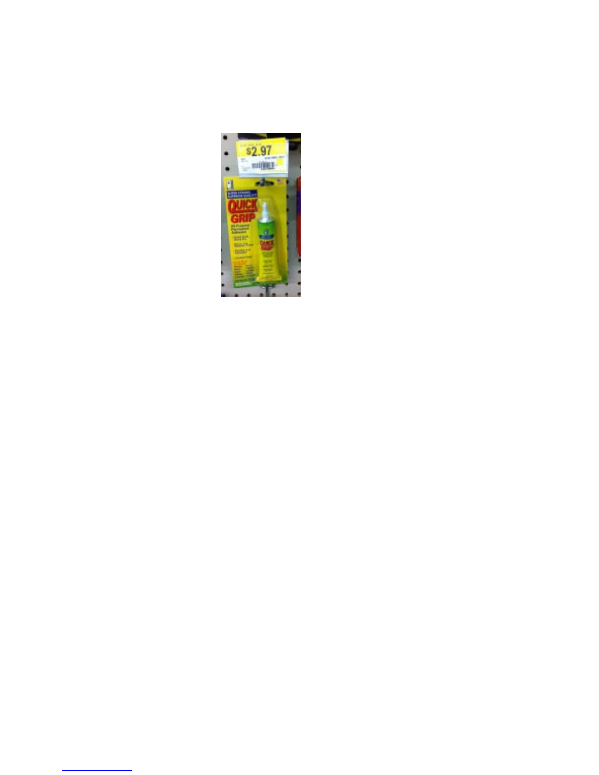
Quick Grip (available at
W almart in craft section)
Masking tape
3/4” roll of fiberglass
reinforced packing tape
Helpful T ools:
40 grit sandpaper on block
(available at auto
finishing stores and Sears)
hobby knife / utility knife
scrap of sheet rock as a “cutting board”
soldering iron, solder
shrink tube insulation
soldering “jig” (ie, extra pair of hands)
heat gun
“hemostat type” pliers
Phillips head screwdriver
straight screwdriver
standard pliers
small clamp
wire cutters
Dremel T ool w/ drum sander
felt tip pen
ruler/straight edge
masking tape
scissors
flat building table, at least 3 ft long
your choice of lightweight finish:
magic markers, or lightweight paint
airbrush (recommended)
Notes on Lithium Polymer (LiPo)
Battery Use:
Firstly, charge Lipos using ONL Y lithium com-
patible chargers according to the manufacturer’s specs.
Secondly: Do NOT drain the batteries to the
point where the plane will no longer fly . Lithium bat-
teries WILL be damaged if they are drained too much.
Notes on Conventions:
References to “Left”, “Right”, “Front” and “Rear”
are assumed to be from a “pilot’ s” point of view as though
(s)he were sitting in the cockpit. Please keep this in mind
when viewing pictures in the construction steps. The
“Leading Edge” of a part is the “front” edge, and is often
abbreviated as “LE”. The “T railing Edge” is the “rear”
edge and usually abbreviated “TE”. The “Fuselage” is
the “body” of the plane and is often called “Fuse” (rhymes
with “loose”) for shorthand. These are common terms in
R/C modeling. “T op” or “Bottom” are as you would expect, with the plane sitting or flying upright. A “root”
edge of something is near the fuselage and is usually bigger than the “tip” which is furthest away. The total length
of a wing is the “span.” A wing usually has a “spar” at the
thickest part running the entire span of the wing.
Notes on Servo setup, control sensitivity
and finishing (paint):
W e supply Hitec HS 55 servos in our deluxe kits,
and these instructions show their installation and use. The
supplied control horn dimensions assume the builder will
use the outermost holes in the Hitec servo arms to give
exciting aerobatic roll-- about 45 degrees of deflection.
This is how we set up our personal planes and what we
use for the aerobatics featured in our videos.
If you desire a more docile plane, move the ez
connector one hole closer to the servo screw . Do NOT
limit the throw using the radio! It’ s always best to do this
mechanically .
For easier control, you may need to program your
elevons so ELEV ATOR percentage travel is less than
AILERON percentage. (It is common for the default
elevon transmitter programs to give a 50/50 mix
contribution for aileron + elevator input).
For aerobatic flying wings it is usually desired to have
much less elevator travel than aileron. Elevator travel may
be as low as 30 to 40% depending on your plane’s weight
and CG . The lighter the plane, the tighter it will turn. If
you have too much elevator throw , your plane could “snap
roll” out of a turn our loop if it’ s heavy. Y our Manta has
great turning traits, and will likely not exhibit this issue if
built according to our directions and not made too heavy .
Keep your paint job light! Beware of spray
paint in cans because it’s easy to make your plane too
heavy when the paint soaks into the foam. Use only light
misting in key areas and avoid coloring the entire plane if
using spray paint in cans. An airbrush gives superior
lightweight paint coverage over cans or brushing.
Page 2
Page 3
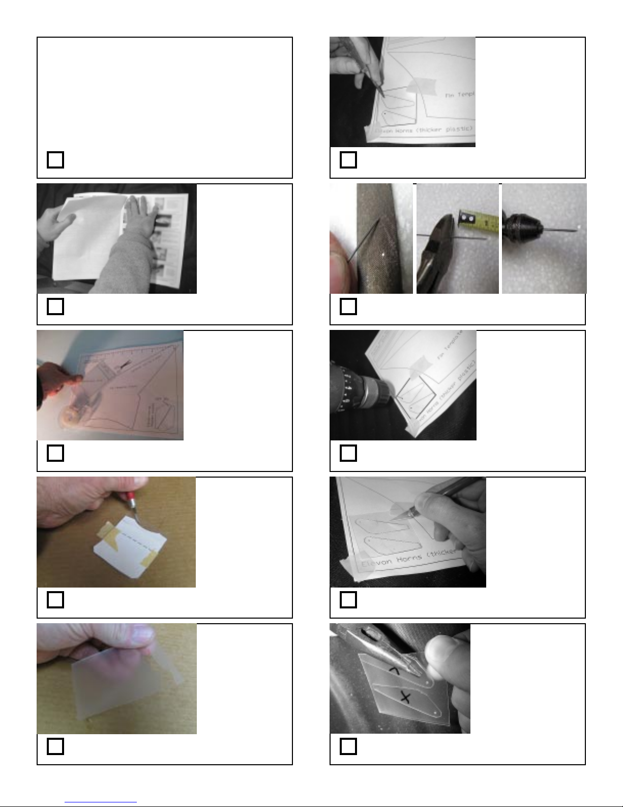
Cut out pieces using paper templates
You’ll need : centerfold template pages
0.039” wire, drill, prick punch
hobby knife, masking tape
both plastic sheet pieces (thick, thin)
EPP foam sheet, wire cutters, metal file
long nose pliers
Step 1: Gather parts and tools
Step 2: Remove centerfold template sheets from
this manual
The paper shows
through the plastic
use a prick punch to
make dimples where
holes will be drilled
in the next step
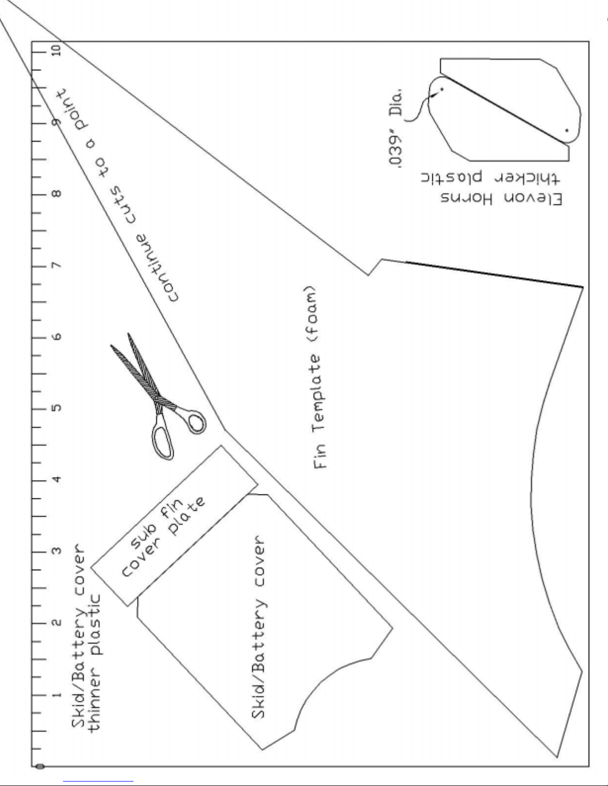
Step 6: T ape thick plastic sheet over
control horn template and mark hole locations
Step 7: Make a “drill bit” from 0.039” wire.
File a point on one end and cut to 3/4” long
careful not to drill
into your table!
Step 3: T ape the thin plastic sheet over the
battery cover template as shown
you don’t need to
cut all the way
through, just
press hard
enough to leave a
groove
Step 4: Score the plastic with a hobby knife
on the outline of the battery cover as shown.
Cut the sub fin
cover plate also
Set these aside for
later
(use a scrap piece of
wood underneath)
Step 8: Drill the two holes with your homemade 0.039” drill bit
Step 9: Now score the horn outlines with a
hobby knife like you did the other pieces.
mark parts with
masking tape or
erasable marker if
you think you might
lose them
Step 5: Bend and snap the part free by flexing
the plastic on the scored outline.
Step 10: Snap out the control horns. Use
pliers to get a better grip on the thick plastic
Page 3
Page 4
Separate the foam sheet
from between the wing
parts if necessary
A piece of scrap drywall
makes a good cutting
board underneath.
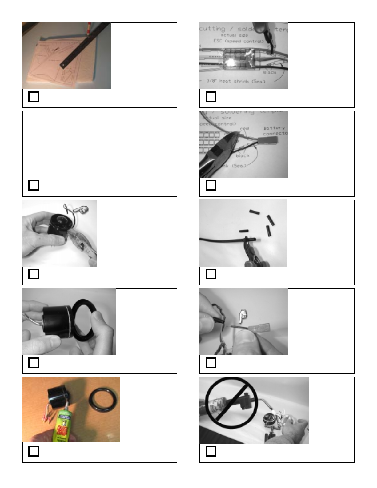
Step 1 1: T ape paper template to foam sheet
and cut out fin with a sharp hobby knife.
Configure motor and radio electronics
You’ll need : Quick Grip, tweezers
hobby knife, masking tape, screwdriver
pliers, solder, soldering iron, heat gun
solder jig, shrink tube, wire cutters
fan unit, ESC, servos, RX, TX, servos
battery connector, battery
Step 12: Gather parts and tools
You can either “peel” it
away as shown, or
break it off in small
pieces.
Don’t worry about
being to neat here
Step 13: Remove the plastic flange around
the motor with pliers as shown
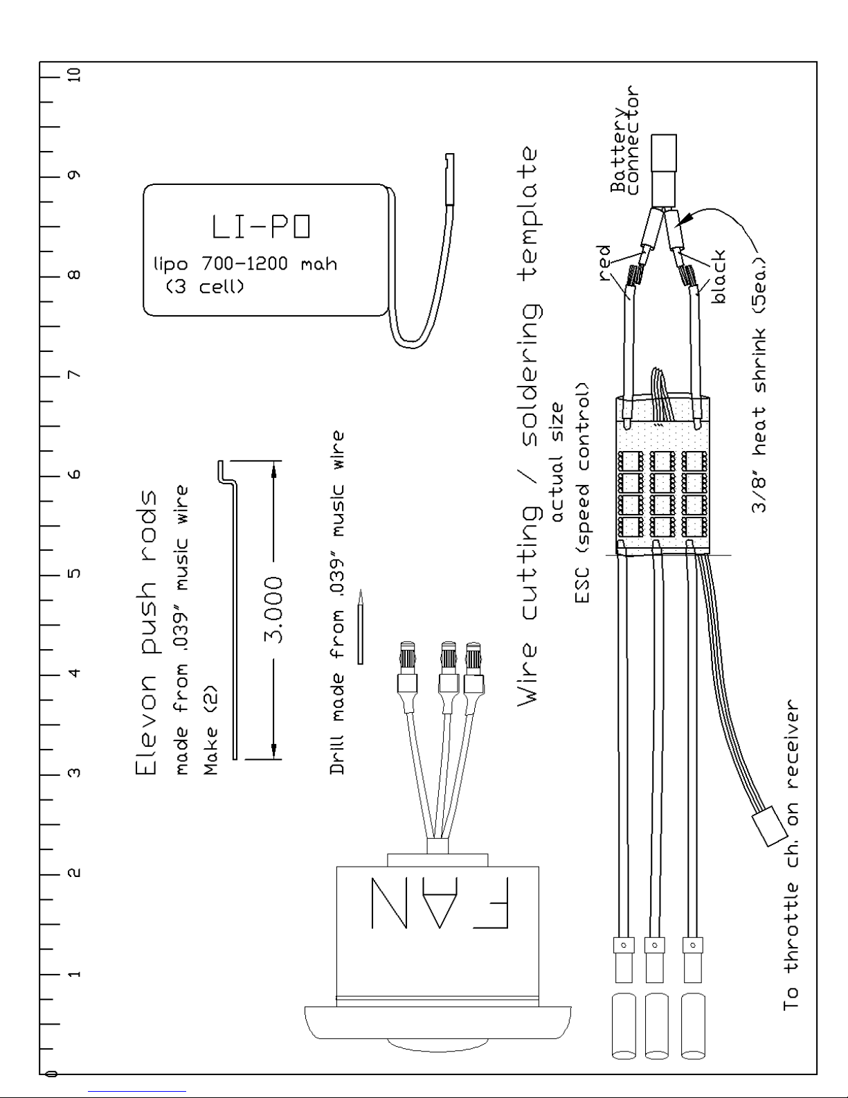
Step 16: Use the full size template on page 12
to cut the ESC battery leads where shown
Depending on your
selected battery size,
you may have a
different connector.
“JST” is shown
Step 17: Cut the battery connector as
shown. Strip 3/16” insulation off wire ends.
Step 18: Cut five sections of heat shrink
tubing about 3/8” long each
Step 14: Apply the fan ring to the front as
shown
Step 15: Glue the ring to the fan with Quick
Grip as shown
Step 19: Slip heat shrink tubes over the
battery connector
take your
time and do
a good job
Blow torches
need not
apply!
Step 20: Solder the wires
Page 4
Page 5
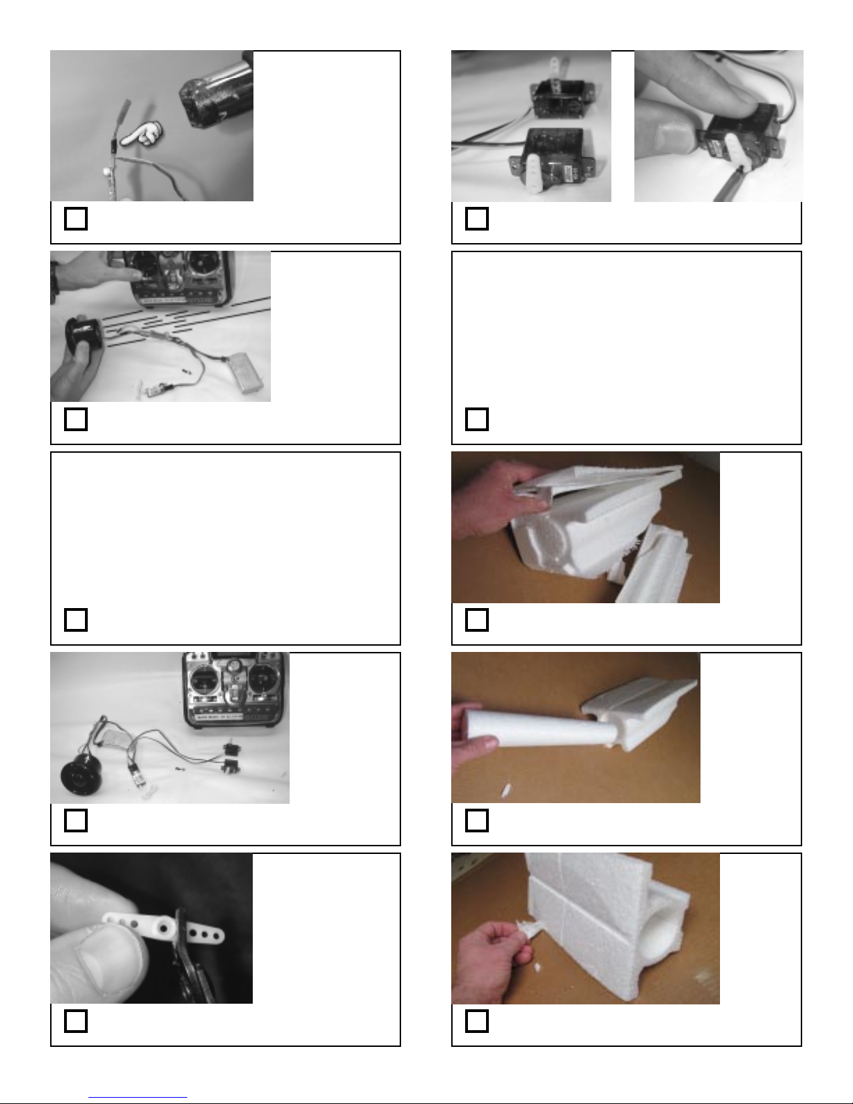
Step 21: Slide the heat shrink tubing to cover
the solder joint and shrink with a heat gun
Step 26: Install servo arms so they are 90
degrees as shown with trims centered
Prepare Wing and Fuselage Foam parts
Carefully test
your motor, then
return your
throttle stick to
the OFF position
Step 22: Hook up all your radio parts then
test fan operation and thrust direction.
Consult ESC directions and adjust small switches
so your fan spins smoothly from low to high
throttle.
W e find the 11.1 V setting sometimes is not
reliable, so select a lower setting to get good
operation.
Step 23: Adjust ESC low voltage cutof f if
needed so fan spins reliably .
You’ll need : Quick Grip
hobby knife, masking tape, CA kicker
40 grit sandpaper on block
Step 27: Gather parts and tools
Step 28: Separate the foam fuselage pieces
as shown
Step 24: Center your radio trims, and
activate your elevon mixing feature.
Step 25: Clip of f one end of the servo arms as
shown
Step 29: Remove the center foam cylinder
and save it for later
Peel away
spider webs
from inside
surfaces too
if you can
reach them.
Step 30: Carefully peel away spider webs.
Page 5
Page 6
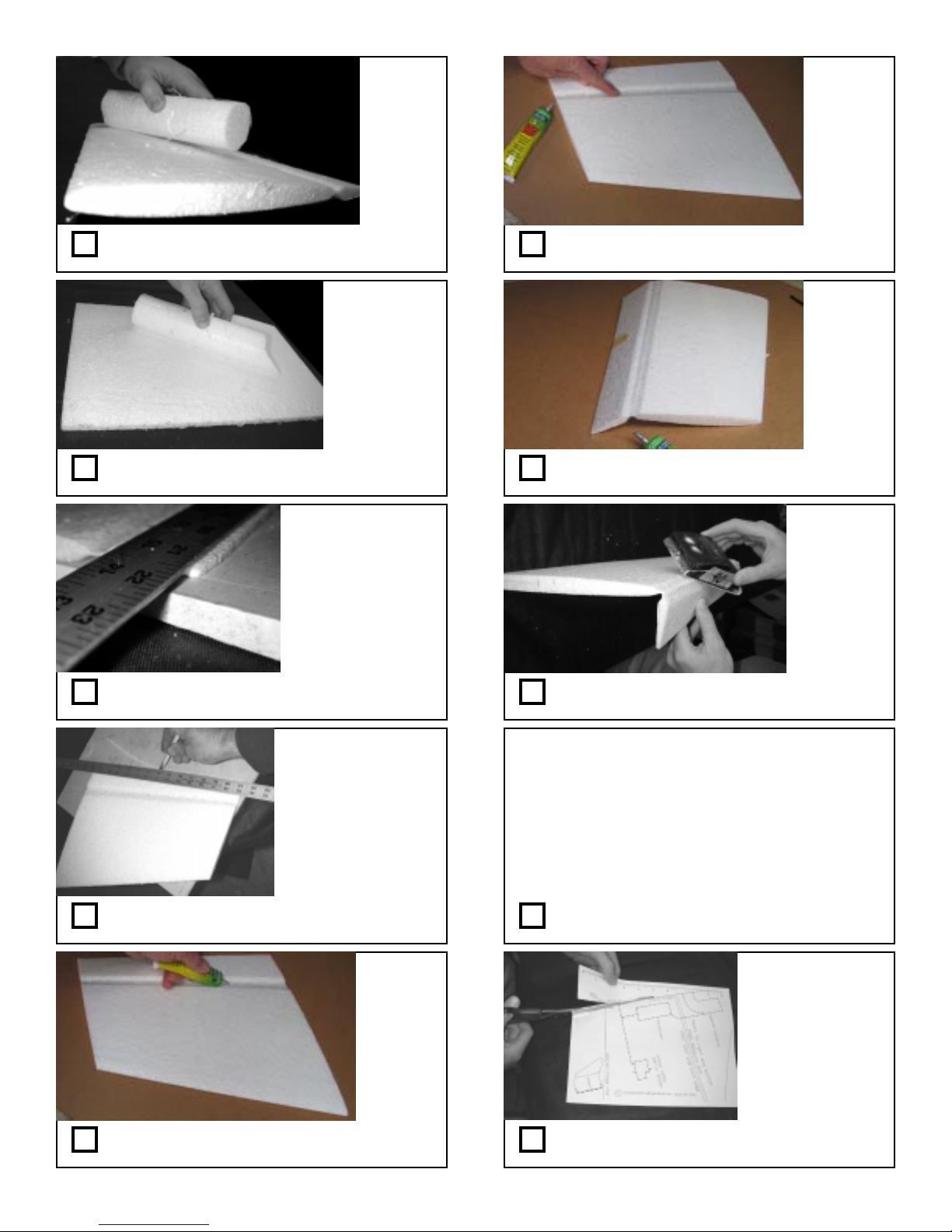
Step 31: Use cylinder to “sand” wing
surfaces to help remove spider webs.
Step 36: Smear the glue with your finger into
the hinge line as shown.
Repeat for
other
wing top
hinge
surface
Step 32: Repeat for all wing surfaces.
place the wing on
a flat cutting
surface
A scrap piece of
drywall makes a
good cutting board
Step 33: Place a metal straight edge along the
wing TE to expose 1/8” of the elevon edge
a sharp hobby knife
works best.
W atch your fingers!
This makes a nice
clean straight TE
Step 34: Trim 1/8” from the elevon rear TE as
shown and discard.
Step 37: Bend the elevon down slightly and
tape in place while glue dries.
this step makes
the hinge more
free
Sand the
BOTTOMS
ONLY
(opposite of
glued sides)
Step 38: Flex the elevons and LIGHTLY
sand the hinge line as shown
Make Wing cavities for component installation
You’ll need : centerfold template sheet,
hobby knife, masking tape,
radio components
pencil, scissors, pliers,
Dremel tool w/ small drum sander
Step 39: Gather parts and tools
Step 35: Apply a bead of Quick Grip to the
hinge line as shown
Quickly
proceed
to the
next step
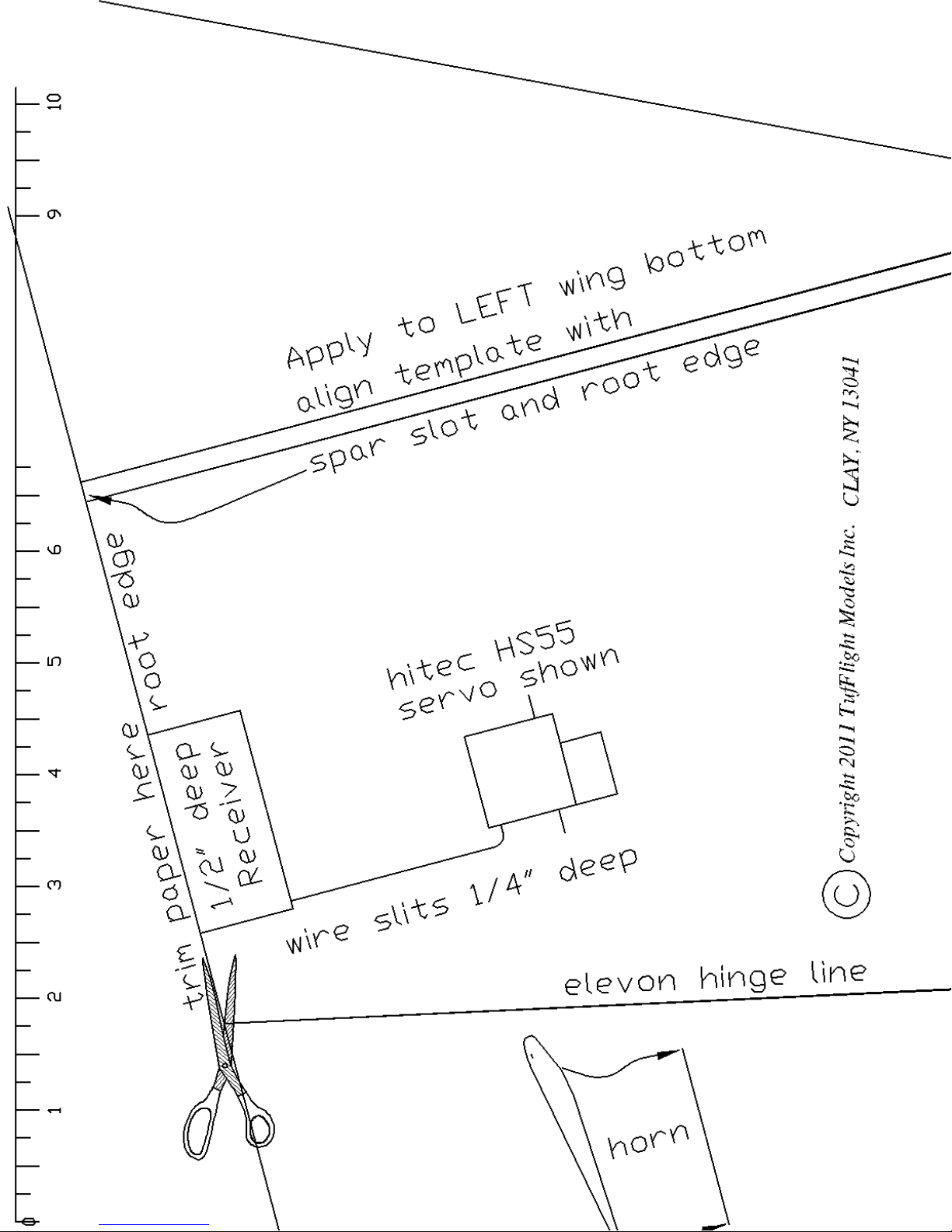
Step 40: Cut the left wing template along the
root edge line where shown
Page 6
Page 7
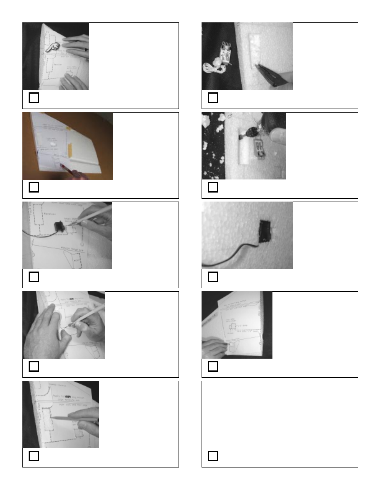
tape template onto wing
bottom (with the spar slot)
using masking tape
If you have a Dremel
tool with a small drum
sander skip to next step
IF you accidentally
pull out foam through
to the top surface, just
glue it back in place
Step 41: Align the template over the left wing
bottom so the spar and root edges match
put the wing on a
cutting board for this
step
(slice all the way
through the foam
holding a sharp hobby
knife vertically)
Step 42: Slice through the template control
horn location where shown
Don’t slice all the way
through the foam!
Use your servo for a
depth gauge and make
the slice the same depth
Step 43: Slice into the servo outline where
shown to the depth of the servo
Step 46: Remove foam from the receiver
cavity area. CAREFULL Y pull out with pliers
firmly hold the drum
sander to the right depth
and slowly proceed
NEAR the edges. When
you get close to the edge,
the foam will “snap”
clean by virtue of the
knife slits
Step 47: The Dremel tool method is superior
for making clean and precise cavities
Step 48: Make servo cavity similarly . T est fit
so the servos lie flush with wing bottom also.
Make the slice
slightly deeper than
your receiver
(about 1/8 to 1/4”
deeper)
Step 44: Slice the outline for the receiver
cavity . Use your receiver for a depth gauge.
Make the pencil marks
dark enough so you can
see the outlines when you
remove the template
Step 45: Trace in all the slices with a pencil so
you don’t lose track of them.
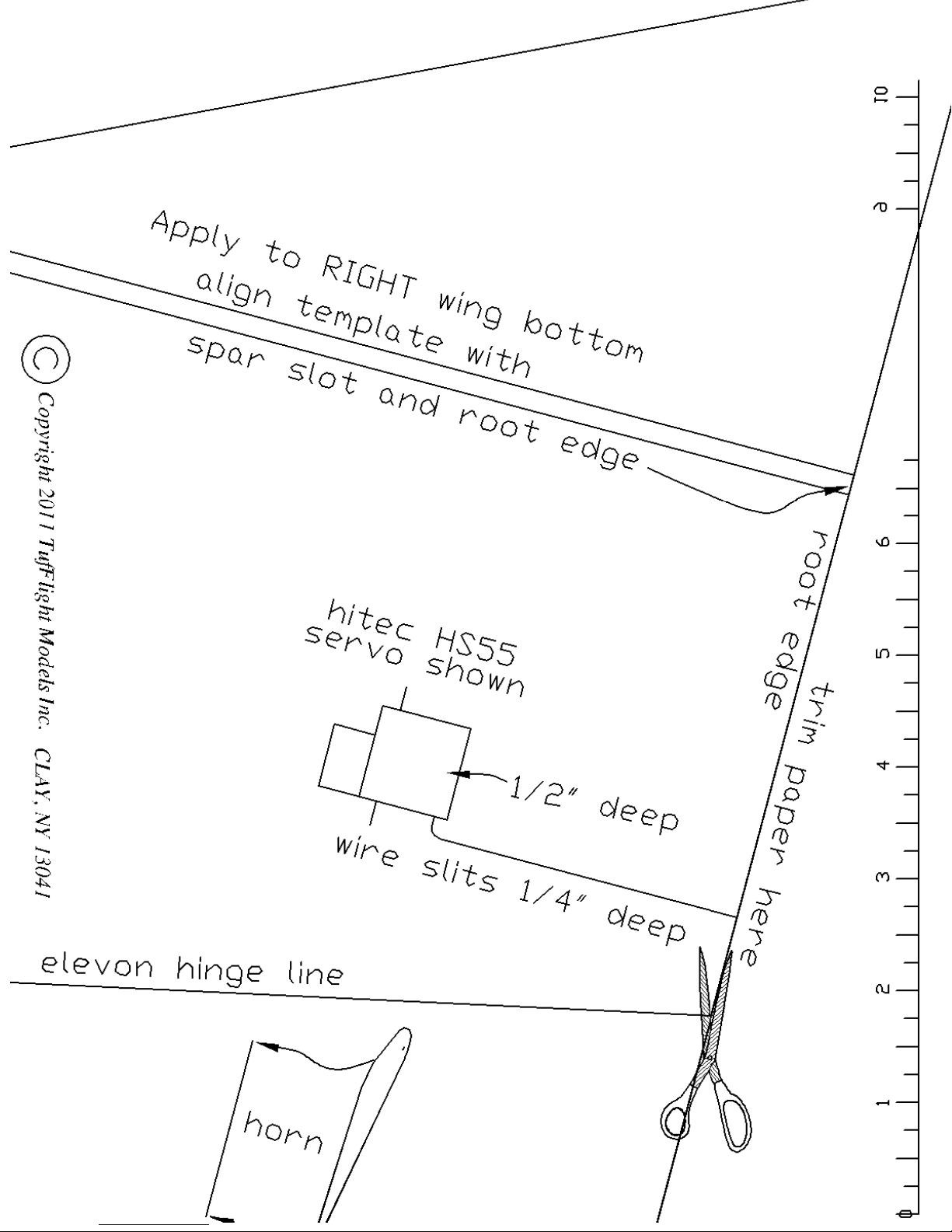
Step 49: Apply the right wing template and
perform these steps similarly for this wing.
Install Fan and Servos
You’ll need : assembled fan and ESC
foam fuselage and wings
Quick Grip,
hobby knife
Step 50: Gather parts and tools
Page 7
Page 8
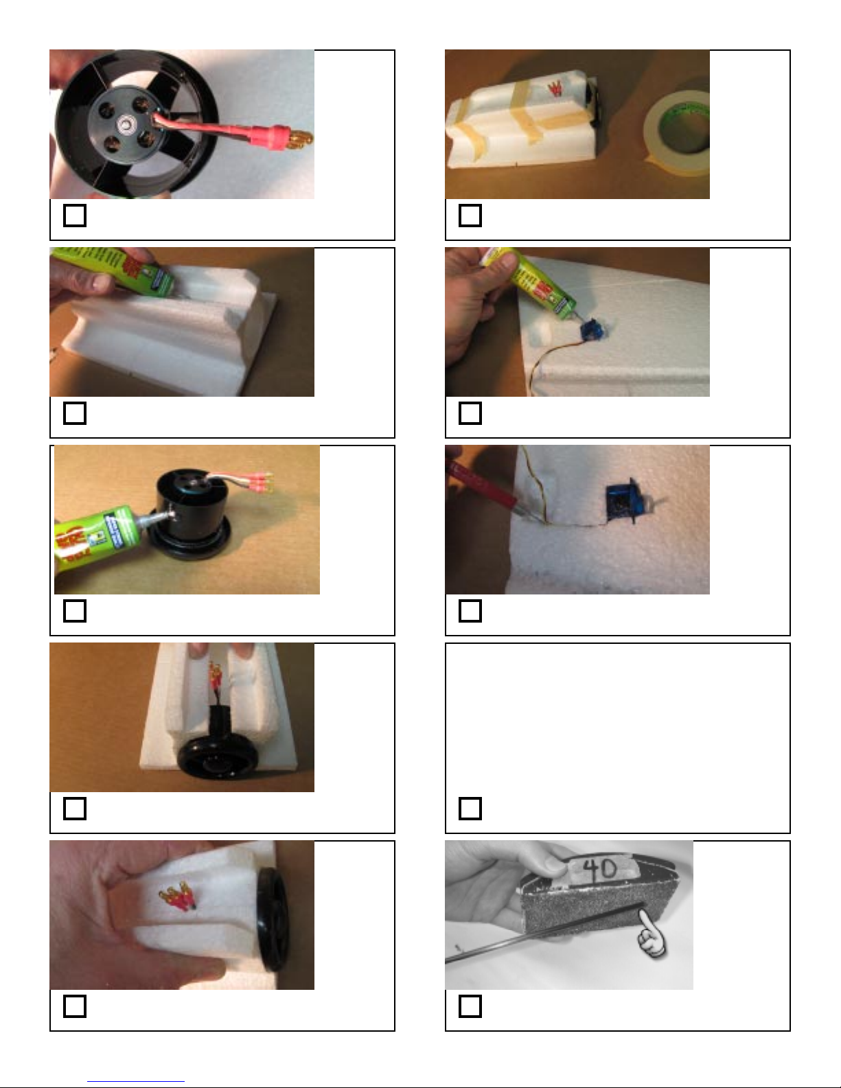
Step 51: Route the motor wires in a line
directly behind one of the stators as shown
Step 56: T ape the fuselage to clamp it while the
glue dries as shown
Do for
other
wing also
Step 52: Apply glue to the center seam as
shown
Step 53: Apply a line of glue around the
body of the fan unit as shown
Step 54: Insert fan into fuselage with wires
pointing as shown
Step 57: Glue servos into wing cavities as
shown
Just do
the left
wing for
now
(with the
RX
cavity)
Step 58: Slice a shallow groove to route the
wires from the servo to the RX cavity .
Assemble wing to fuselage
You’ll need : foam fuselage, foam wings,
carbon spar, masking tape,
sandpaper on block,
Quick Grip
Step 59: Gather parts and tools
Step 55: Squeeze the fuselage together as
shown
Step 60: deburr both ends of the carbon spar
with a sanding block
Page 8
Page 9

Page 9
Page 10
Page 12
Page 10
Page 11

Page 11
Page 12
Page 12
Page 13
Page 13
Page 14

Page 14
Page 15
Page 17
Page 15
Page 16

Page 16
Page 17
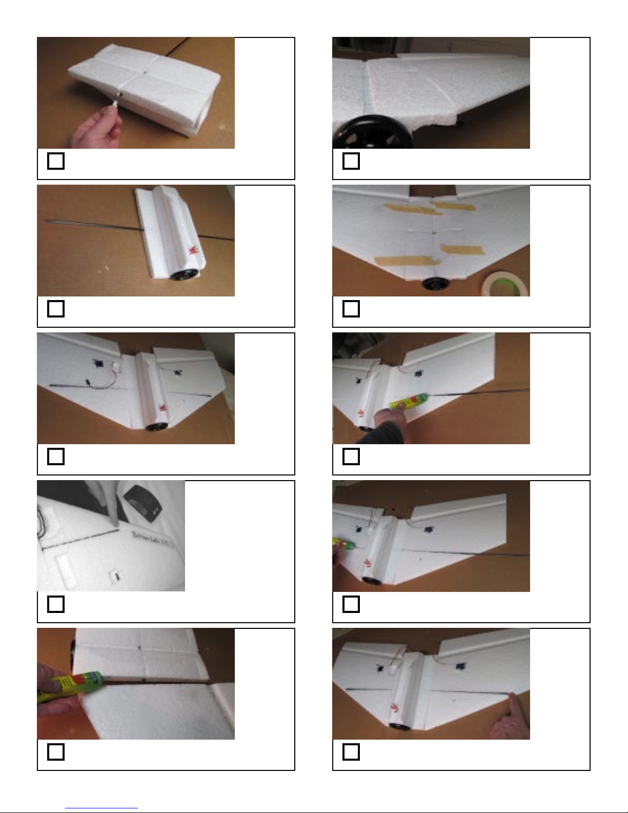
Step 61: Insert the spar into the fuselage
hole where shown
Step 66: Be sure the surfaces are flush as
shown
Step 62: Center the spar as shown in this and
following steps
Step 63: Align the wing surfaces even with
the fuselage as shown
Step 64: Examine the spar ends and sand
them flush if they protrude slightly
Step 67: Use masking tape to tightly hold the
joint together
Step 68: Carefully slide out the spar and apply
glue into the groove as shown.
Step 69: Apply glue to other wing also
Step 65: Separate and apply Quick Grip into
the joint as shown
don’t glue
the spar
yet
Repeat for
both wing/
fuse joints
Wipe away
any glue
which
squirts out
of the spar
joint
Step 70: Reinsert the spar twirling it as you go
to help evenly distribute the glue
Page 17
Page 18
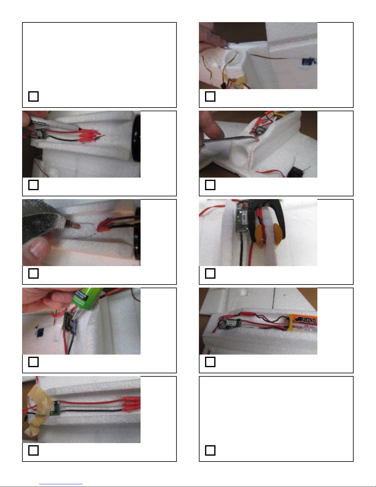
Install ESC components
You’ll need : assembled wing and fuselage
ESC assembly, small plastic clamp
Quick Grip, hobby knife, battery,
Dremel Tool with drum sander
hemostat pliers, masking tape,
transmitter, marker
cut a smooth
path from the
servo to the
receiver
cavity just
deep enough
to hide the
wire
Step 71: Gather parts and tools Step 76: With a sharp knife, carefully route the
right wing servo wire as shown.
test motor
direction
(Consult
Step 22)
Step 72: Correctly connect wires and bend
back . Trace around connectors as shown.
Step 73: Using a Dremel tool, create a
cavity so the connectors will “lie flat.”
Step 74: Apply glue to the ESC
Step 77: Also slice a path from the ESC to the
receiver for the throttle connection as shown.
Note
connector
faces
forward
Step 78: Apply Quick Grip to the Battery
connector and clamp to fuse where shown.
Step 79: Completed fuselage bottom.
Step 75: T ape ESC to fuse where shown
while glue dries.
Configure Controls and Install Receiver
You’ll need : assembled wing and fuselage
Quick Grip, push rod template, pliers
control horns, ez connectors, sandpaper,
push rod wire, screwdrivers,wire cutters
radio receiver, transmitter, battery,
hobby knife, white packing tape
Step 80: Gather parts and tools
Page 18
Page 19
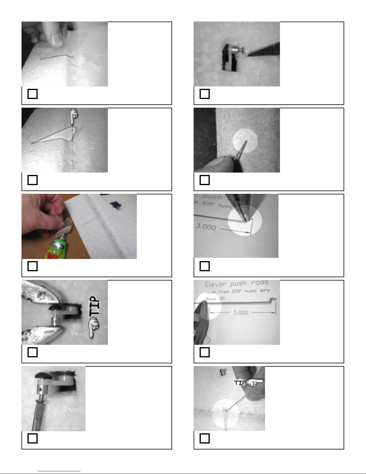
Bottom
Surface
also see next step
for proper location
(this IS critical for
a good flying
plane, so take your
time here)
Turn on your
radio and
operate servo
for the full
range to test
Step 81: T est fit the plastic control horn into
the elevon slot. Enlarge slot as needed.
Control horn
bottom edge
should be flush
with elevon top
surface
Step 82: Place it so the hole is even with the
hingeline when the wing is flat on the table
Step 83: Apply Quick Grip to the control horn
and glue in place.
Step 86: Make clearance in the foam as
needed for full servo travel
Step 87: Deburr ends of the 0.039” wire
with sandpaper
Step 88: Make push rods with Z bends using
full size template on page 12 as shown
Use the outermost
holes in the servo
arm now .
If you want more
docile controls, you
choose an inner hole
later on.
Step 84: Install the mini ez connectors into
the servo arms as shown
*Note, these picture shows our
Stingray which is a bottom wing
plane with servo arms
protruding through top surface.
Your Manta servo installation
will look slightly different, but
this process is the same.
Step 85: Install screw into connector as shown Step 90: Insert Z bend into control horn as
Step 89: Cut push rod to length and repeat
for other
shown
Page 19
Page 20
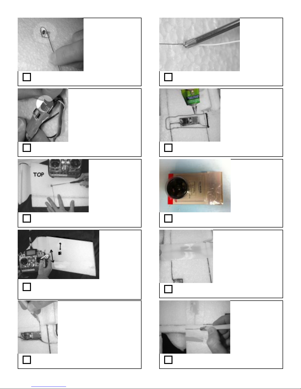
Step 91: Insert other end into ez connector
as shown
Note a long 72
MHz receiver
antenna wire is
shown
If using 2.4 GHz,
your slits may be
very short and near
the receiver cavity
Step 96: Install the RX antenna wire into the slit
with a phillips head screwdriver
Smear it over the foam
so it coats it over a 2”
wide section and
longer than the cavity
This helps the tape
stick in the next steps
Step 92: Make all receiver connections if not
already done.
Step 93: Turn on radio and center trims.
Tighten screw when elevon is “flat”
Up elevator (down
stick) makes both
servo arms push the
elevons up
Right aileron
(right stick) makes
right servo push,
and left servo pull
Step 94: T est your radio elevon program to
ensure servos move correctly . Reprogram or
switch wires if needed.
Step 97: Tuck wires neatly into RX cavity and
apply Quick Grip to the perimeter as shown
Step 98: Remove the white packing tape from
the motor/ESC package
Step 99: Apply tape over receiver cavity as
shown.
Make a long continuous slice just
long enough for the length of your
RX antenna wire in the wing bottom
(opposite RX and ESC)
Try to route it away from the spar
and all other wires, and keep about
2” forward of the elevon hinge line
at the control horn location
Step 95: Make a shallow slit to hide the RX
antenna on the wing bottom surface
Step 100: Trim excess tape with knife.
Page 20
Page 21
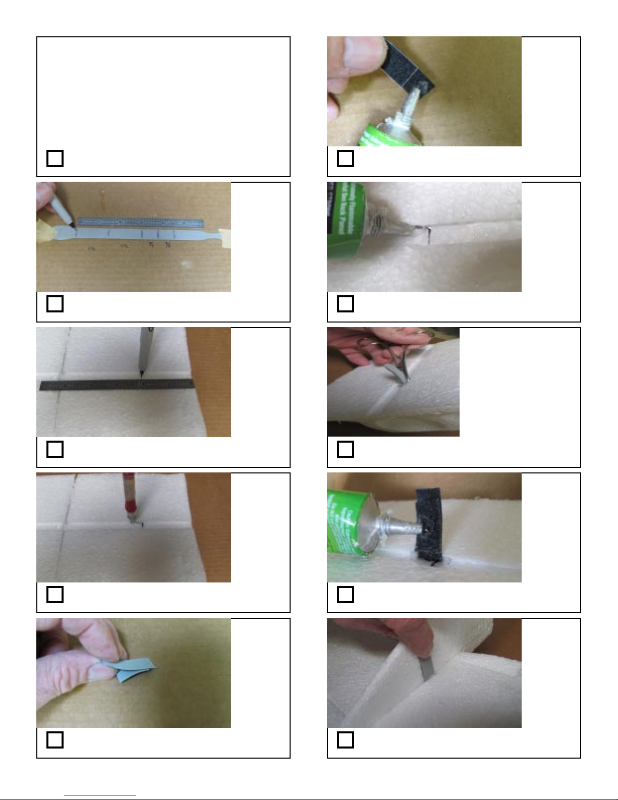
Install Fin
You’ll need : assembled wing and fuselage
Quick Grip, foam fin, velcro strip,
hobby knife, ruler, small clamp,
scissors, hemostat pliers
Step 101: Gather parts and tools
Step 102: Mark and cut two (2) 1-1/2” and
two (2) 3/4” pieces from velcro strap
Step 103: Mark the fin groove 2” from the
rear as shown
Step 106: Apply glue to the exposed portion
of the longer piece as shown.
Step 107: Apply glue in one of the slots
Hemostat pliers work well
for this
Wipe away any glue which
squirts out of the slot
Allow glue to dry before
proceeding
Step 108: Shove the glued area into the slot
with the smaller pad facing inward as shown.
Step 104: Slice the foam to receive the
velcro strap on each edge of the groove
Step 105: Place a short and long piece of
velcro together as shown (stick together)
Step 109: Apply glue to the inner pad as
shown.
Step 1 10: Insert fin into slot and glue pad to
fin as shown
Page 21
Page 22
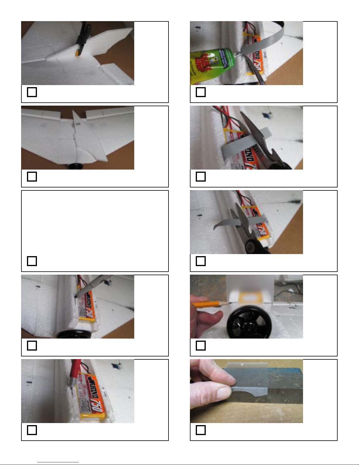
Step 1 1 1: Clamp in pace while glue dries.
Repeat steps for velcro on other side.
Fin shown
flipped
around
illustrating
easier
storage and
transport
Step 1 16: Glue one end of a velcro strip
down into one slit.
Step 1 12: Fin is now removable after glue
dries. (Note “sub fin” not shown in above pic)
Install Battery Holder
You’ll need : assembled wing and fuselage
Quick Grip, velcro strip, marker,
velcro pads, battery cover,
block or table edge with sharp corners
Step 101: Gather parts and tools
Step 1 14: Mark the fuselage bottom at the
center of your battery as shown
Step 1 17: Cut excess strap which extends
beyond battery as shown.
Step 1 18: Glue remaining velcro strap into
other slit and trim similarly .
Step 1 19: Place battery cover with curved
recess to fan and mark corner as shown
Step 1 15: Make deep slits on each side of
your battery as shown with knife.
Step 120: Crease the cover on marks using
a sharp edge. Bend it to a right angle.
Page 22
Page 23
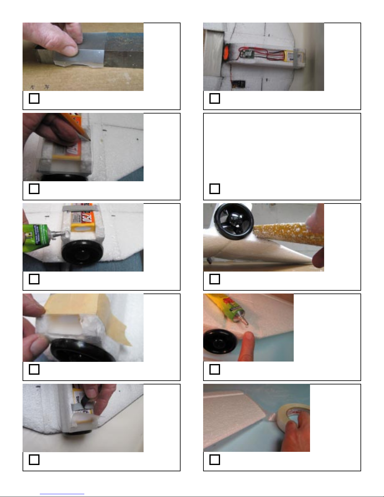
Step 121: Repeat second crease to fit
fuselage as shown.
Step 122: Lay cover in place, mark and
trim as needed to be even with fuselage
sides.
Step 126: Completed fuselage bottom
Final Assembly
You’ll need : assembled wing and fuselage,
40 grit sanding dowel, ruler, marker,
sub fin cover plate
Optional: Quick Grip,
3/4” wide fiberglass packing tape,
airbrush, paint
Step 127: Gather parts and tools
Step 123: Apply cover to front corners as
shown
Step 124: T ape Cover in place while glue
dries
Step 125: Cover flips up for battery access.
Step 128: Sand the fuselage wing transition
to give a pleasing blended contour
Optional Step:
This gives more
durable leading edge
and allows better
adhesion with
reinforcement tape in
following steps
Step 129: Smear some Quick grip onto the
entire leading edge of the plane.
Optional Step:
This gives more
durable leading
edge
Step 130: Apply fiberglass packing tape to
the ENTIRE wing leading edge
Page 23
Page 24
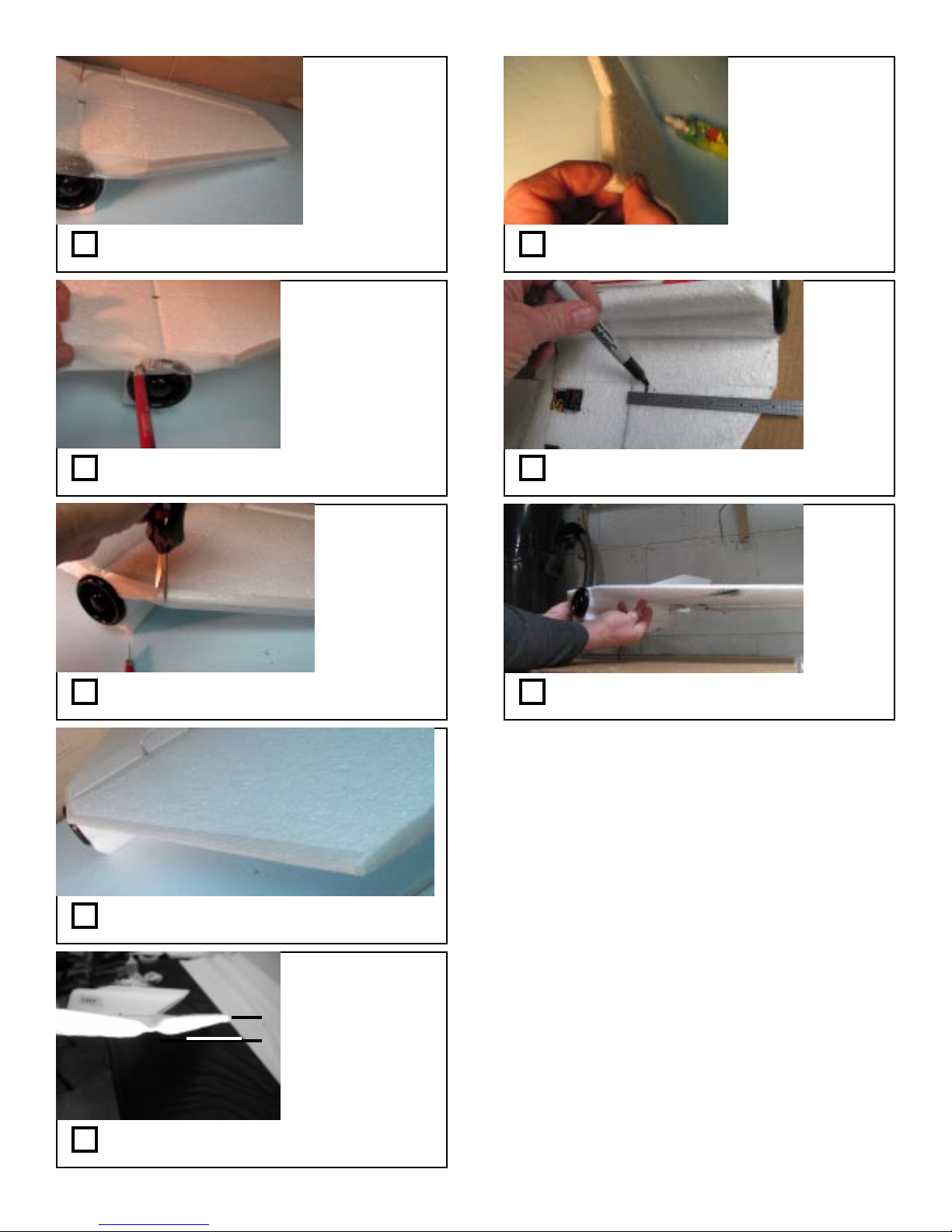
Optional Step:
This gives more
durable leading
edge
Step 131: Continue to neatly wrap the tape
across the ENTIRE leading edge
Optional Step:
This gives more
durable leading edge
Try not to cut ALL the
fibers to preserve
strength
Step 132: Cut the tape where it lies over the
inside of the fan lip.
Optional Step:
This gives more
durable leading
edge
Try not to cut ALL
the fibers to
preserve strength
Step 133: Cut/pleat the tape at the wing/fuse
junction so it will lay flat.
Step 136: Glue the sub fin cover plate to the
fin as shown
mark
both
sides
Step 137: Mark locations 3/4” ahead of the
spar on wing bottoms as shown
plane sits
level with
fingers on
the marks
as shown
Step 138: Move battery as needed to balance
after painting with all parts assembled.
Step 134: Optional: If used, smooth the
tape to the contour of the leading edge.
5/8”
This is a good
starting point
to fly .
Step 135: Program your elevator travel so it
moves only 5/8” up and 5/8” down from neutral
Flight Trim:
A good test for an aerobatic CG position is to fly the
plane upright and trim the elevator for level flight. Then
fly inverted and see how much down elevator control is
needed to maintain level flight. If the plane flies level inverted with very little down elevator , the CG is good.
The farther back your CG moves the more “twitchy” your
elevator will become. Conversely , the farther forward your
CG moves, the more elevator travel you will need to maintain the same turning radius. Adjust to your tastes by
sliding the battery fore or aft.
Have Fun!
Remember, weight is the enemy , so keep decorations and repairs light!
W e welcome any feedback you may have on this or
other TufFlight products.
Please feel free to contact us via our website :
www .tufflight.com
take care and enjoy!
Mark & Joe
Page 24
 Loading...