


5376 Amalfi Drive, Clay, NY 13041 www.tufflight.com
The Toughest R/C Planes Ever!
Wingspan: 40"
Length: 44"
Flying Weight: 24 oz
Motor: Himax HC3510-1100
brushless outrunner or
Radio: 4 channels
Servos: 4 (HS 65 or equivalent)
Wing Area: 429 sq in
Hello, and thanks for buying the Bouncer! Whether you’ve just entered the exciting world of radio control and 3D
flying, or you’re a seasoned veteran, the Bouncer is the perfect combination of agility, durability, versatility and value for the
school or front yard 3D flyer.
Caution: The Bouncer can be a very agile performer, and requires care in setup and operation. Please obey
manufacturer’s safety rules for your motor, propeller and battery. Lithium polymer (lipo) batteries are ideal for
this plane. Charge lipo batteries ONLY with a lithium capable charger according to battery instructions.
Bouncer
250 W equivalent
Excellent 3D capability
-plus-
Outstanding Durability
The CG location is 5-1/2” from the wing leading edge at the root.
(6-1/2” for expert)
While you may be tempted to fly close to yourself, please practice in a safe manner.
Please read and understand the instructions before starting to build. We recommend joining the AMA and
following the AMA safety code. Call 1 (800) I- FLY-AMA for more details.
We assume no responsibility for how you use your plane. That said, let's get started!
Items Included in kit:
Foam Parts:
(1) right/left EPP wing cores in shucks
(2) EPP tail feathers sheets in shucks with wings
(1) EPP front fuselage piece
(1) EPP rear fuselage piece
Misc:
(1) 0.030” control horn plastic sheet
(1) clear mylar hinge sheet
(1) 1/32” G10 sheet
(1) 3/16” white plastic motor mount sheet
(2) 3/32” x 1/2” fiberglass LG struts
(2) 1/16” x 72” fiberglass rod
(1) 1/8” x 24" fiberglass rod
(1) popsicle stick
(1) 0.193” x 0.023” x 18” carbon
Hardware:
(4) Dubro mini EZ connectors
(2) main wheels
(1) tailwheel
(2) 6-32 x 3/8” nylon bolts
(2) 6-32 x 1-1/4” steel bolts
(6) 6-32 nuts
(1) 0.039” x 18” wire
(1) 1/16” x 7” wire
(3) zip ties
(12) O-rings #017
(1) Velcro strap
This Instruction Manual
Rev 1.6
Page 1

Items needed to complete:
Equipment:
Himax HC3510-1100 brushless outrunner
or 250 W equivalent
4 channel radio receiver
30 - 35A electronic speed control (ESC)
1200 mAH - 2200 mAH 3S Lipo battery
4 servos: Hitec 65 or equivalent
Parts:
props :
APC 11 x 3.8 Slo Flyer -orAPC 11 x 5.5 E
(2) 12” servo wire extensions
connectors for ESC and battery
solder (if needed for connectors)
shrink tube (if needed for solder joints)
Adhesives:
Gorilla Glue (clear, dries white), small bottle
--and/or-Quick Grip adhesive
(available at Walmart and Michaels crafts)
thin CA (regular, NOT foam safe)
CA accelerator (kicker)
masking tape
3M77 Spray adhesive
Helpful Tools:
40 grit sandpaper on block
(found at auto finishing stores and Sears)
hobby knife / utility knife
new single edge razor blade
scrap of sheet rock as a “cutting board”
soldering iron
Phillips head screwdriver
straight screwdrivers
long nose pliers
wire cutters
Drill with 7/64”, 9/64”, 1/8”, 1/16” bits
Dremel Tool w/ drum sander and cutoff wheel
razor saw
felt tip pen
ruler/straight edge
metal file
scissors
clamps
plastic wrap
flat building table, at least 3 ft long
lightweight decorations: airbrush (recommended)
Flight Trim:
The recommended center of gravity (CG) point is
5-1/2” from the LE at the wing root with the battery installed. Adjust by positioning the battery by moving the
G10 plate and velcro strap on the fuselage for the new
battery position.
A good test for an aerobatic CG position is to fly the
plane upright and trim the elevator for level flight. Then
fly inverted and see if any down elevator control is needed
to maintain level flight. If the plane also flys level inverted with very little down elevator, the CG is good
for 3D. The farther back your CG moves, the more
“twitchy” your elevator will get. For 3D It helps to have
40 to 50 degrees deflection on all surfaces and a rearward CG. 30 to 50% expo may also be helpful on all
surfaces (Especially elevator). Adjust to your taste.
You may wish to check and adjust lateral balance.
It should be very close to neutral if built as shown.
For hints on flying 3D maneuvers, consult our web
site: http://www.tufflight.com/3d_faq.html
Notes on Crashing and Repairs:
You should be able to fix foam damage with Quick
Grip for fast field repairs. Apply Quick Grip to one surface, join parts temporarily, pull apart to let dry for about
30 seconds (you should see “spider webs”) and then put
them back together. In a few minutes the joint will be
flight ready. Large damaged areas will benefit from Gorilla glue as it foams to fill voids.
Have Fun!
Remember, weight is the enemy, so keep repairs
light! If there's one thing we've learned, it's amazing how
much cosmetic damage can be "ignored" when a friend
shows up to fly.
We want you to have fun exploring the limits, but
please do so safely.
We welcome any feedback you may have on this or
other TufFlight products.
Please feel free to contact us:
take care and enjoy!
Mark & Joe
Page 2

Assemble Wings
You’ll need : Foam wing pieces, mylar hinge sheet,
medium and thin CA, kicker,
hobby knife, scissors, razor blade, ruler,
cutting board, scrap wood,
scrap EPP / 40 grit sanding block
Step 1: Gather parts and tools. Step 6: With a new sharp hobby knife, slice
the ailerons apart on the center marks.
Step 2: Carefully separate the wing parts from
the shucks as shown.
A scrap piece of
EPP may also be
used to “sand” off
the spider webs
Step 3: Sand and peel any “spider webs”
away from the foam.
Step 4: Mark the aileron piece center at one
end as shown
Step 7: Ailerons should be identical
The beveled
(pointed) edges
face each other
Step 8: Align aileron to wing as shown
Step 9: Trim Aileron to match wing angle
with sharp hobby knife as shown
Step 5: Mark center at the other end also
Step 10: Make slicing tool from scrap wood
and razor blade exactly 0.350” thick
Page 3

A ruler helps to
keep the hinge/
foam joint together
Step 11: Glue razor blade to scrap wood as
shown
Work
carefully
and press
all parts to
the bench
when
slicing
Step 12: Slice the aileron LE and wing TE with
tool as shown
mylar is
0.003”
thick and
comes
rolled in
“the
baggie”
Step 13: Cut two 3/4” strips of mylar for
hinges
Step 16: Apply kicker to hinge.
Step 17: Trim hinge at angle as shown to aid
insertion during next step
Step 18: Slide hinged aileron into wing as
shown.
Tape a
credit card
to the
mylar strip
to help
feed it into
the slit
Step 14: Slide mylar hinge into aileron as
shown
Step 19: Flex the aileron to set the hinge gap
needed to provide adequate clearance.
The hinge
gap should
be as small
as possible
while still
allowing full
deflection as
shown
After this
step, trim
hinge
material
even
with
root/tip
edges
Step 15: Apply thin CA to hinge on both sides Step 20: Once hinge gap ready, apply thin
CA and kicker while clamping with ruler
Page 4

Assemble Fuselage
You’ll need : Foam fuselage pieces, ruler,
white gorilla glue or quick grip glue,
scrap EPP / 40 grit sanding block,
sharp knife, 1/16” fiberglass rods, ruler
dremel tool /cutoff wheel
Step 21: Gather parts and tools.
You’ll use the 33”
pieces now. Save
the longer ones for
the wing later
Step 22: Cut the fiberglass rods to produce
two (2) 39” and two (2) 33” pieces
Step 23: Glue front/rear fuse pieces together
and tape the joint while the glue cures.
Step 26: Mark fuselage above elevator slot
as shown. Repeat for other side.
Step 27: Make a slice roughly 1/8” deep with
sharp knife connecting marks as shown.
Step 28: (continuation) Slice from front to
rear as shown.
Step 24: Sand and/or trim with a knife the
glue which squirts out of the joint
Step 25: Mark fuselage front at center of
side “bulge”. Repeat for other side.
Sand/
blend the
foam joint
for a
smooth
transition
as needed/
desired
Work glue into
the entire slot
from nose to tail.
Step 29: Apply white Gorilla Glue or Quick
Grip into slot as shown.
fiberglass rod
shown black in
pictures-- your
color may vary
Step 30: Lay fiberglass rod into groove and
press down so it’s flush with surface.
Page 5
Repeat for
both sides.
Insure fuselage
is straight
while glue
cures.
(These should lie
3 - 15/16” from LE
at root, 2-7/8” from
LE at tip
Make 4 spanwise
slices-- one on
each wing surface)
Step 31: Work rod into slot. Rod will stay in
place once glue starts to set.
Join Wings to Fuselage
You’ll need : Assembled Foam fuselage and wings,
white gorilla glue or quick grip glue,
hobby knife, (2) 1/16” fiberglass rods,
tall blocks/supports, weights, ruler,
plastic wrap, medium CA, kicker
old credit card
Step 32: Gather parts and tools.
measure from
FRONT-- not
motor cutout
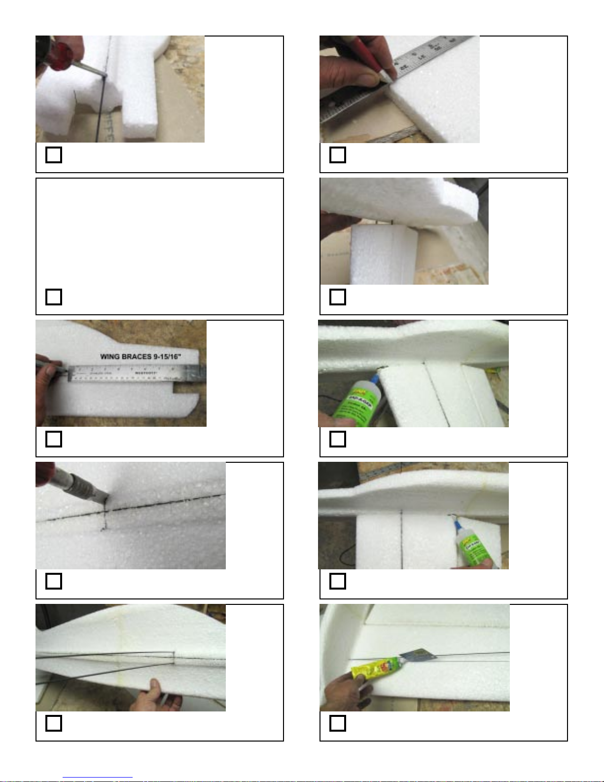
Step 33: Mark fuselage 9-15/16” from nose
as shown (both sides)
Step 36: Find spanwise index marks on
wings and slice 1/8” deep along these lines
Step 37: Insert wings between spars guiding
them into the slices to locate the wings.
use
medium
CA and
kicker
Step 38: When satisfied with wing position,
tack glue wing front to fuselage where shown.
Step 34: Slice all the way through fuselage
at the marks as shown.
Step 35: Thread the 1/16” rods half way
through the slices as shown.
This
quickly
locks
wing into
position
for next
steps
Step 39: Tack glue rear of wing similarly.
Work
quickly
for this
and the
following
steps-one wing
at a time
Step 40: Apply white gorilla glue or quick
grip into wing slots with an old credit card
Page 6

Note: In the following steps, the Himax motor is
shown which requires shaft reversal.
Your motor may not require this procedure.
Step 41: Work Spars into slots being careful
to center them along the span (other half too)
Repeat for
all wing
spars
Step 42: Wipe away any glue which squirts out
with acetone and paper towel.
We use
two
identical
radio
boxes
Step 43: Lay onto blocks upside down as
shown. Blocks should be taller than canopy.
Step 46: Prepare your chosen motor for
mounting
Make Motor Mount
You’ll need : Himax HC3510-1100 or
equivalent w/ tools, and prop mount,
loc tite, 1/8”, 1/4”, 1/2” drills, saw,
motor mount white plastic, scissors,
paper motor mount template (“H”),
scrap wood, hammer or vise, knife, 3M77
Step 47: Gather parts and tools.
Step 48: Remove hex screws as shown
Step 44: Apply white gorilla glue or quick
grip into center wing/fuse joint as shown.
Step 45: Apply weights while glue cures as
shown.
Step 49: Remove collar as shown.
Take care to
insure fuse is
perpendicular to
wing and things
look symmetrical
Step 50: Remove washer and save in safe
place. Separate as shown.
Page 7

Step 51: Insert motor shaft into wood block
as shown
Using slow pressure
with a vise is
preferable if
available
Step 56: Apply washer.
Step 52: Press motor shaft forward (check
next photo to know when to stop)
Step 53: Motor shaft should look like this.
Step 54: Re-assemble motor as shown.
Step 57: Install wheel collar.
Step 58: Cut out “H” motor mount from
paper template as shown.
Step 59: Apply template to white plastic
sheet.
Step 55: Loc tite all screws.
Step 60: Drill 1/8” holes where shown.
Page 8

Step 61: Drill central 1/2” hole where
indicated.
Step 66: Deburr corners of holes
Note wires route
on left side of
fuselage
(fuselage dowels
won’t be
installed yet at
this point)
Step 62: Drill 1/4” holes where indicated at
“H” corners
A band or scroll
saw may also be
used if available
Step 63: Saw to remove “H” insides as
shown.
Step 64: Saw to remove “H” insides as shown.
A band or scroll saw may also be used.
Step 67: Test fit motor to “H” mount and
adjust holes if needed.
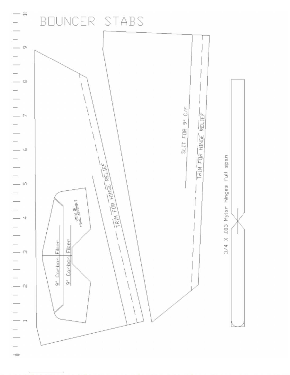
Make Tail Parts
You’ll need : Foam sheets, new sharp hobby knife,
paper templates, 3M77, carbon strip,
white gorilla glue or quick grip, ruler,
cutting board, mylar hinge material,
clamps, assembled wing/fuselage
Step 68: Gather parts and tools.
Step 69: Remove any spider webs from
foam. Apply templates
*Note, cutouts are
NOT identical
Top cutout is
smaller than
bottom -- label Top
/ bottom to avoid
confusion later
Step 65: Round edges with knife or disc
sander as shown
Step 70: Cut tail parts from foam sheets
with sharp knife
Page 9

Step 71: Cut two elevators from the same
template.
Step 76: Bevel the rudder and elevator to
allow desired deflection
Step 72: Slice the elevator and horizontal stab
where shown for the carbon stiffeners.
You can re-use the
aileron hinge
slicer if you sand it
thinner to center it
to the tail parts
Step 73: Make slices for 3/4” wide mylar
hinges as indicated.
Step 74: Slice the rear fuselage for the 3/4”
hinges also
Step 77: Cut two 9” carbon pieces.
Step 78: Glue the carbon stiffeners into the
elevator and horizontal stab as shown.
Use a
technique
similar to
how you
hinged the
ailerons.
Step 79: Glue the mylar hinge into the
elevator and horiz stab with thin CA.
Step 75: Glue the two elevator and stab
halves together as shown.
Step 80: Center the assembled horizontal
stabilizer/ elevator into the fuselage as shown
Page 10

Page 11

Page 12

Page 13

Page 14

Page 15
Page 16

Page 17

Page 18

Page 19

Page 20

Bouncer graphic courtesy of David Killius
Drawing A
Page 21

Step 81: Measure and align the stab to the
wing to insure symmetry
Step 86: Glue Rudder to fin / fuselage with
thin CA and kicker
Make Template Parts
You’ll need : paper templates, 3M77 spray adhesive,
G10 Material, clear plastic, scotch tape,
scissors, hobby knife, mineral spirits,
clamps, 1/8” fiberglass rod, 0.039” wire, file,
white gorilla glue or quick grip, mineral
spirits, pen, Dremel tool/cutoff wheel
Step 82: Mark position when satisfied
Check and
adjust stab to
make sure it is
level with the
wing.
Clamp or shim as
needed
Step 83: Apply white gorilla glue or quick
grip and glue stab into fuse
make
lower
hinge
extra long
(3/4” x 11/2”) to
reinforce
rudder
Step 84: Apply mylar hinges to rudder using
same technique.
Step 87: Gather parts and tools.
Step 88: Apply control horn template to clear
plastic as shown
Step 89: Cut out parts with scissors.
Step 85: Carve clearance angles as needed to
clear horizontal tail parts when deflected.
Scoring and
bending/snapping
will free the parts
more easily than
cutting all the way
through
Step 90: A hobby knife can be used for tight
corners.
Page 22

Step 91: Locate the 0.039” wire and file
one end to a sharp point as shown.
Step 96: Apply template to G10 with 3M77
as shown.
Step 92: Cut the sharpened wire to 1” as
shown.
Step 93: Chuck your “home made bit” into a
drill (or Dremel) and drill holes where indicated.
Step 94: Remove templates from parts. Mineral spirits makes this easy.
Step 97: Drill holes as indicated.
Aviation
shears or tin
snips work
well
Step 98: Cut out parts with strong scissors.
Step 99: Cut out fuse motor mount/dowel
holes paper template as shown.
Step 95: Cut template for G10 parts as
shown.
Step 100: Align template to nose and mark
hole locations as shown with pen.
Page 23

The Motor mount “H” plate
will attach snugly behind
these rods.
Be careful NOT to give UP or
DOWN thrust, only right
thrust
Step 101: Slice through nose to make holes
for rods
You’ll need the
(2) 2-3/4” rods
now.
(save the other
rods for later).
Step 102: Cut the 1/8” fiberglass rod to these
dimensions : (1) 15”, (2) 2-3/4”, (2) 1-1/8”
All holes in G10
go closest to
motor cavity
Step 103: Glue rod to G10 to fuselage as
shown with white gorilla glue or quick grip
Step 106: Align rods so they give approximately 2 degrees of “right thrust” as shown
Step 107: When satisfied with all angles,
clamp in place while glue cures.
Badger “Createx”
paints are water
based and durable
When airbrushed,
they give a
brilliant
lightweight result
Step 108: OPTIONAL - Now is a good time
for painting, or wait to the end-- your choice
Step 104: Repeat for bottom
Step 105: Glue G10 reinforcements to other
side as shown.
Install Radio Parts
You’ll need : pen, hobby knife, Dremel tool, ruler,
control horns, ez-connectors, 0.39” wire,
white gorilla glue or quick grip, pliers,
radio system, battery, ESC
Step 109: Gather parts and tools.
We recommend a
1200 to 2200mAH
3S lipo pack for
best results.
Step 110: Obtain your battery and charge it.
Page 24

Plane RIGHT
BOTTOM side
shown
Don’t forget servo
arms and screws!
Servo arms must
point straight up
with radio turned
on and trims
centered
Step 111: Mark receiver location on fuselage
side/bottom about 1-1/2” from hinge line
Step 112: Slice hole through fuselage for
receiver installation
Plug aileron
servos into RX to
be sure the servo
locations are
within reach and
equidistant from
center
Step 113: Mark servo locations so their wires
will BOTH reach the receiver 1-1/2” from hinge
Step 116: Glue aileron servos into foam with
white gorilla glue or quick grip.
slice
servo
cavity all
the way
through
the
fuselage
Step 117: Locate rudder servo 3-3/4” forward
of hinge line as shown and slice cavity
Test fit
servos
into
cavity,
then
remove
for next
steps
Step 118: Locate elevator servo even with stab
front as shown and slice cavity similarly
A dremel
tool with
drum
sander
works well
after slicing
the outline
Step 114: Slice servo outlines with sharp hobby
knife and clear foam to make cavity as shown
Step 115: Test fit servo and make slits in foam
for wire to RX as shown.
Step 119: Extend and route servo wires to
RX. Make slits and channels to hide wires
Step 120: Solder or insert extensions as
desired. Forcep “pull tools” helps route wires
Page 25

Note control horn
“bottom” should be
flush with other side
of aileron. Enlarge
slice as needed.
Step 121: Pull and tuck wires in place, then
glue servos into cavities.
Install servo arms
so they are
centered
(Transmitter trim
and stick neutral
with servo arms
perpendicular)
Step 122: Hook up and and test your radio
to insure controls move as intended.
Step 123: Install EZ connectors on all servo
arms.
Step 126: Insert control horns and apply thin
CA and kicker to both sides. (top too).
Step 127: Make Z bends in wire as shown.
Install into aileron EZ connectors.
Step 128: Make slice for elevator control
horn as shown.
Note shape of
control horn-- the
point at the front
will inset
perfectly with
point of the
aileron at the
hinge line
Step 124: Use control horn to mark location
for installation. Push rod should be straight.
Step 125: Make slice all the way through
the aileron and hinge as shown.
Test fit slit in
horn over
carbon
stiffener and
adjust slit as
needed for
snug fit.
Step 129: Make slice and test fit elevator
control horn as shown.
Step 130: Install elevator and rudder control
horns and rods as you did for the ailerons.
Page 26

Trim extra push
rods after all
controls centered
and EZ
connectors
adjusted.
Note the location
of the corner on
the spar
(repeat for both
LG locations-left/right)
Step 131: Adjust push rods to center controls
as needed and tighten EZ connectors..
We feel the excellent “all
terrain” landing gear adds
another dimension to the
Bouncer. It certainly flys very
well WITH gear, however if
you’d like to save some
weight and time, you may omit
the following section.
Step 132: Decide if you want landing gear.
All LG parts together weigh about 2.5 oz
Install Landing Gear
You’ll need : pen, hobby knife, Dremel tool, ruler,
1/8” fiberglass rods, 1/16” wire, scissors,
white gorilla glue or quick grip, clamps,
popsicle stick, wheels, nylon screws
nuts, landing gear struts, sandpaper, pliers,
scrap paper, steel bolts, CA kicker,
G10 parts, rubber bands/O-rings
Step 133: Gather parts and tools.
Step 136: Align the support as shown and
mark the location of the hole on the line
Remove paper in center so
fuselage clears template.
Align edge of paper with
marks from previous step
The paper edge marks
location of LG spar to be
inserted into wing and
through fuselage
Step 137: Make a template from scrap
paper and mark wing where LG rod goes
Step 138: Cut popsicle stick in half and glue
between two supports with rod as shown.
Step 134: Mark the wing bottoms 4-1/2”
from each root edge as shown (left and right)
Step 135: Use a G10 LG support to mark
from spar forward along these lines as shown
Sand LG strut
corners round. Also
sand LG support
edges round where
rubber band/O-ring
rubs to avoid cutting.
Step 139: Drill LG struts according to template. Mount wheels with steel bolts and nuts.
Step 140: Attach struts to supports with nylon
bolt and nuts. Make both assemblies.
Page 27

Step 141: With a sharp hobby knife, slice
the borders for the LG supports as shown.
Careful not to poke
through top surface.
(glue will fill holes in
following steps anyway in
case you do!)
Also don’t grind away
any spar material.
Step 146: Once supports and rod fit well,
glue with white gorilla glue.
Step 142: Using Dremel tool with collet as
depth gage, make slots in wing between slices
Test fit LG support
into slot periodically
to test your progress
Step 143: A Dremel tool with router attachment helps control the cutting.
Use a
long knife
or sharp
file for
this
Step 144: Poke hole through fuselage for
LG rod as shown.
Step 147: Attach rubber bands/O rings as
shown.
Refer to template
pages for tailwheel
bending guide.
Step 148: Make a small bend in 1/16” wire
as shown.
Step 149: Make next bend to trap tailwheel
and continue bending as template shows.
15” rod should go in
supports and lie flush
with wing surface.
Cut groove and poke/
slice hole through fuse
to allow rod to lie
straight (see next step)
Step 145: Test fit gear supports and 15” rod.
Clear any foam which prevents full insertion.
Step 150: Make final bends and trim wire
according to template.
Page 28

Slice should be next
to hinge for best
strength.
Step 151: Slice the rudder as shown to
receive wire.
Refer to template for
G10 reinforcement
location
Step 152: Apply Quick grip or white Gorilla
Glue and G10 supports and clamp till dry.
Final Assembly
You’ll need : pen, hobby knife, Dremel tool, ruler,
“H” motor mount, rubber bands/O rings,
battery, velcro strap,
Scrap wood or plastic
(ie credit card thickness,
zip ties, scrap 1/16” rod, motor, ESC
Step 153: Gather parts and tools.
Step 156: Insert round grinder into Dremel
tool.
Step 157: Make “half round” slots as shown
between your marks for rods to seat.
Step 158: Mount motor to “H” mount with
bolts, washers and loc tite as shown.
Step 154: Insert “H” mount as shown with
bottom groove being longest
Motor thrust line
should be about 1/4”
above wing /fuse
center
See Drawing A in
center of manual
Step 155: Use center hole to orient the “H”
mount and mark rod locations on “H” mount
Step 159: Insert motor assembly as shown.
Step 160: Place mount to back side of rods
and insure clearance exists for next steps.
Page 29

Step 161: Apply rubber bands (or O rings)
as shown.
Step 166: Insert another zip tie around ESC
rear wires as shown.
Step 162: Stretch behind “H” mount and
around rod as shown.
Step 163: Mount secured as shown. Repeat for all 4 corners of “H” mount.
Make 2 slices -one above, one
below
Step 164: Slice through fuse to poke zip tie
around G10 reinforcements as shown.
Step 167: A scrap piece of 1/16” rod will
prevent zip tie from pulling through hole
CG may be
up to 6-1/2”
from the LE
for great
waterfalls
Step 168: Mark CG location 5-1/2” from LE
at wing root
Step 169: Place battery on wing top left side
and move to balance on the marks.
Step 165: Insert zip tie around ESC wires and
tighten as shown
Step 170: With battery at balance position,
mark spot for battery lead to poke through
Page 30

Step 171: Make hole in wing to clear
battery connector
Step 176: Glue G10 beneath velcro strap as
shown.
Step 172: Mark center of battery as shown.
Step 173: Slice through fuselage above and
below battery edges as shown.
Step 174: Insert velcro strap through
fuselage to hold battery.
Step 177: Route, tuck, hide remaining wires
as desired.
Optional Items
You’ll need : pen, hobby knife, covering iron, mylar,
drill, scrap 1/16” rod,
quick grip, clear plastic wing root joiner ,
airbrush, paint
Step 178: Gather parts and tools.
Locate “wing root
joiner” which was
made from the
template when the
control horns were
cut from the thick
clear plastic sheet
Step 179: Slice through the fuselage and
both wings as shown for wing root joiner
Step 175: Cut scrap wood or plastic to act as
backer support to fit between slits (height of
battery).
This helps prevent
the wings from
separating in hard
nose down crashes.
It can be installed
at any time.
Step 180: Insert joiner and glue with quick
grip to lock both wings together.
Page 31

A covering iron
turned up to the
“high” setting
helps this step
Step 181: Apply quick grip to wing tip
bottoms
Step 182: Apply mylar strips to avoid scuffs
when taxiing “aggressively” over pavement.
This helps to give
the foam a
protective skin to
resist tearing.
Step 183: Smear Quick Grip over any foam
corners likely to contact the ground.
Step 184: Sand or melt the fuselage corners
smooth and round as desired.
Badger “Createx”
paints are water
based and durable
Step 185: Airbrush canopy and other
decorations as desired.
GO FLY !
Step 186: Install scrap 1/16” rod where shown to extend the life of rubber bands or O-rings. This prevents
them from getting caught “in the scissors” if the LG struts pivot too far rearward.
Page 32
 Loading...