

Page 1
INSTALLATION MANUAL
2”, 3” OR 4” FRONT AND REAR
SPRING SUSPENSION SYSTEM
CHEVY PICKUP 3/4 TON
1973 —– 1987
PART # 14721
SJ052102
PART NUMBER : 14721
1973 — 1987 CHEVY PICK UP 3/4 TON
2”, 3” OR 4” FRONT AND REAR SPRING
SUSPENSION SYSTEM
PARTS LIST:
Part # Description Qty.
5U-6109R 5/8” X 3 1/2” X 9 5/8” Round U-bolts 5
5U-3507R 5/8” X 3” X 7 5/8” Round U-bolts 3
58NW 5/8” High Nuts & Washers 2
GMSBNB1 Front Spring Eye Bolts 1
GMSBNB3 Rear Spring Eye Bolts 1
GMBLNB Front & Rear Brake Line
Extensions & Hardware 1
LUBE Lube Pack 2
14721INST Instruction Sheet 1
Congratulations on your selection to purchase a Tuff
Country EZ-Ride Suspension System. We at Tuff
Country are proud to offer a high quality product at the
industries most competitive pricing. Thank you for your
confidence in us, and our product.
Before installation begins, it is the customers/installers
responsibility to make sure that all parts are on hand. If
any parts are missing, please feel free to call one of our
customer service representative @ (800) 288-2190.
Make sure to use locktite on all new and stock hardware
associated with this installation.
Torque Settings
5/16” 15—18 ft lbs.
3/8” 28—32 ft lbs.
7/16” 30—35 ft lbs.
1/2” 65—85 ft lbs.
9/16” 85—120 ft lbs.
5/8” 95—130 ft lbs.
3/4” 100—140 ft lbs.
Tuff Country EZ-Ride Suspension highly recommends that a qualified and or certified mechanic performs this installation.
If you desire to return your vehicle to stock, it is the
customers responsibility to save all stock hardware.
This vehicles reaction and handling characteristics
may differ from standard cars and/or trucks. Modifications to improve and/or enhance off road performance may raise the intended center of gravity. Extreme caution must be utilized when encountering
driving conditions which may cause vehicle imbalance or loss of control. DRIVE SAFELY! Avoid
abrupt maneuvers, such as sudden sharp turns
which could cause a roll over, resulting in serious
injury or death.
It is the customers responsibility to make sure that a
re-torque is performed on all hardware associated
with this suspension system after the first 500 miles
of installation. It is also the customers responsibility
to do a complete re-torque after every 3000 miles or
after every off road use.
After the original installation, Tuff Country EZ-Ride
Suspension also recommends having the alignment
check every 6 months to ensure proper tracking,
proper wear on tires and front end components. Tuff
Country EZ-Ride Suspension take no responsibility
for abuse, improper installation or improper suspension maintenance.
It is the responsibility of the customer or the mechanic to wear safety glasses at all times when performing this installation.
It is the customers/installers responsibility to read
and understand all steps before installation begins.
OEM manual should be used as a reference guide.
The Tuff Country EZ-Ride Suspension product safety
label that is included in your kit box must be installed inside the cab in plain view of all occupants.
It is the responsibility of the installers to make sure
that the rear view mirror hanger is hung from the
rear view mirror. The rear view mirror hanger has
instructions on proper post installation procedure.
IMPORTANT CUSTOMER INFORMATION
Page 2
LIMITED LIFETIME WARRENTY
Notice to all Tuff Country EZ-Ride Suspension
customers: It is your responsibility to keep your
original sales receipt! If failure should occur on any
Tuff Country EZ-Ride Suspension component, your
original sales receipt must accompany the warranted
unit to receive warranty. Warranty will be void if the
customer can not provide the original sales receipt.
Do not install a body lift in conjunction with a
suspension system. If a body lift is used in
conjunction with any Tuff Country EZ-Ride
Suspension product, your Tuff Country EZ-Ride
Suspension WARRANTY WILL BE VOID.
Country Inc. (“Tuff Country” ) suspension products
are warranted to be free from defects in material and
workmanship for life if purchased, installed and
maintained on a non-commercial vehicle; otherwise,
for a period of twelve (12) months, from the date of
purchase and installation on a commercial vehicle,
or twelve thousand (12,000) miles (which ever occurs
first). Tuff Country does not warrant or make any
representations concerning Tuff Country Products
when not installed and used strictly in accordance
with the manufacturer’s instructions for such
installation and operation and accordance with good
installation and maintenance practices of the
automotive industry. This warranty does not apply to
the cosmetic finish of Tuff Country products nor to
Tuff Country products which have been altered,
improperly installed, maintained, used or repaired, or
damaged by accident, negligence, misuse or racing.
(“Racing is used in its broadest sense, and, for
example, without regards to formalities in relation to
prizes, competition, etc.) This warranty is void if the
product is removed from the original vehicle and reinstalled on that or any other vehicle. This warranty
is exclusive and is in lieu of any implied warranty of
merchantability, fitness for a particular purpose or
other warranty of quality, whether express or
implied, except the warranty of title. All implied
warranties are limited to the duration of this
warranty. The remedies set forth in this warranty are
exclusive. This warranty excludes all labor charges
or other incidental of consequential damages. Any
part or product returned for warranty claim must be
returned through the dealer of the distributor from
whom it was purchased. Tuff Country reserves the
right to examine all parts returned to it for warranty
claim to determine whether or not any such part has
failed because of defect in material or workmanship.
The obligation of Tuff Country under this warranty
shall be limited to repairing, replacing or crediting, at
its option, any part or product found to be so
defective. Regardless of whether any part is
repaired, replaced or credited under this warranty,
shipping and/or transportation charges on the return
of such product must be prepaid by the customer
under this warranty.
Tuff
Special Note: This box kit is used on 2”, 3” or 4” kits,
it includes the front and rear U-bolts, front and rear
brake line extensions, front and rear spring eye bolts
and all necessary hardware.
If you are installing a 2” Tuff Country EZ-Ride
Suspension on your vehicle, please read the
following:
Tuff Country EZ-Ride Suspension offers two styles
of front springs, a Heavy Duty spring and a EZ-Ride
spring. If you have not already ordered your front
springs, please contact Tuff Country or your local
Tuff Country dealer and order (2) 18270 (Front EZRide Springs) or (2) 18271 (Front Heavy Duty
Springs). Also Chevy/GMC offers (2) different length
rear springs, a 52” rear leaf spring and a 56” rear leaf
spring. If the vehicle that you are working on has a
52” rear leaf spring, and you have not already
ordered your rear leaf springs, please contact Tuff
Country or your local Tuff Country dealer and order
(2) 19270 (Rear 52” EZ-Ride Spring). Unfortunately
Tuff Country EZ-Ride Suspension does not offer a
56” rear leaf spring. Also, Tuff Country EZ-Ride
Suspension recommends running a 32” x 10.50” tire
for maximum tire clearance. Special Note: This tire
size in not 100% accurate due to variations in wheel
width, wheel off set, tire diameters and driving
habits.
If you are installing a 3” Tuff Country EZ-Ride
Suspension on your vehicle, please read the
following:
Tuff Country EZ-Ride Suspension offers two styles
of front springs, a Heavy Duty spring and a EZ-Ride
spring. If you have not already ordered your front
springs, please contact Tuff Country or your local
Tuff Country dealer and order (2) 18370 (Front EZRide Springs) or (2) 18371 (Front Heavy Duty
Springs). Also Chevy/GMC offers (2) different length
rear springs, a 52” rear leaf spring and a 56” rear leaf
spring. If the vehicle that you are working on has a
52” rear leaf spring, and you have not already
ordered your rear leaf springs, please contact Tuff
Country or your local Tuff Country dealer and order
(2) 19370 (Rear 52” EZ-Ride Spring). Unfortunately
Tuff Country EZ-Ride Suspension does not offer a
56” rear leaf spring. Also, Tuff Country EZ-Ride
Suspension recommends running a 32” x 12.50” tire
for maximum tire clearance. Special Note: This tire
size in not 100% accurate due to variations in wheel
width, wheel off set, tire diameters and driving
habits.
Page 3

If you are installing a 4” Tuff Country EZ-Ride
Suspension on your vehicle, please read the
following:
Tuff Country EZ-Ride Suspension offers two styles
of front springs, a Heavy Duty spring and a EZ-Ride
spring. If you have not already ordered your front
springs, please contact Tuff Country or your local
Tuff Country dealer and order (2) 18470 (Front EZRide Springs) or (2) 18471 (Front Heavy Duty
Springs). Also Chevy/GMC offers (2) different length
rear springs, a 52” rear leaf spring and a 56” rear leaf
spring. If you have not already ordered your rear
springs, please contact Tuff Country or your local
Tuff Country dealer and order (2) 19470 (Rear 52” EZRide Spring) or (2) 19471 (Rear 56” EZ-Ride Spring).
Also, Tuff Country EZ-Ride Suspension recommends
running a 33” x 12.50” tire for maximum tire
clearance. Special Note: This tire size in not 100%
accurate due to variations in wheel width, wheel off
set, tire diameters and driving habits. Tuff Country
EZ-Ride Suspension highly recommends installing a
raised steering arm once a 4” suspension system
has been installed. If you have not already ordered
your raised steering arm, please contact Tuff
Country or your local Tuff Country dealer and order
part # 70100.
Please Follow Instruction Carefully
Before installation begins, drive and check to make
sure there are no uncommon sounds and or frame
damage. Also at this time measure from the center of
the hub to the bottom of the fender well and record
measurements below.
Pre Installation Measurements:
Driver Side Front:______________________________
Passenger Side Front:__________________________
Driver Side Rear:______________________________
Passenger Side Rear:__________________________
At the end of the installation take the same
measurements and compare to the pre-installation
measurements.
Post Installation Measurements:
Driver Side Front:______________________________
Passenger Side Front:__________________________
Driver Side Rear:______________________________
Passenger Side Rear:__________________________
Front End Installation:
1. To begin installation, block the rear tires of the vehicle
so that the vehicle is stable and can’t roll backwards.
Safely lift the front of the vehicle and support the frame
with jack stands. Place a jack stand on both the driver
and passenger side. Next remove the wheels and tires
from both sides.
2. Working on the driver side, remove the stock shock
from the stock upper and lower mounting point and save
hardware for later re-installation. The stock shocks may
be discarded. Special Note: New longer front shocks
are needed, if you have not already ordered shocks,
please contact Tuff Country or your local Tuff
Country dealer and order the proper shocks. Tuff
Country recommends using a 20” fully extended
nitrogen gas shock when installing a 2” suspension
system and a 23” fully extended nitrogen gas shock
when installing a 3” or 4” suspension system.
Repeat procedure on the passenger side. Special Note:
If the vehicle that you are working on has the dual
shock option, remove both shocks and discard.
3. Working on the driver side, disconnect the stock brake
line at the frame mount. Let the stock brake line hang.
Special Note: Brake fluid is going to leak out, it is a
good idea to place a bucket under the vehicle to
catch the brake fluid that will leak out. After the
installation is complete, the brake lines will need to
be bleed. Repeat procedure on the passenger side.
See Illustration # 1
4. Working on the driver side, remove the stock cotter pin
and caster nut that connects the stock drag link ball joint
to the stock steering arm. If you are not going to replace
the stock steering arm with a raised steering arm, save
the stock cotter pin and caster nut for later re-installation.
Remove the stock drag link from the stock steering arm
and let the stock drag link hang. Special Note: Tuff
Country EZ-Ride Suspension highly recommends
installing a raised steering arm once a 4”
suspension system has been installed. If you have
not already ordered your raised steering, please
contact Tuff Country or your local Tuff Country
dealer and order part # 70100. If you are installing a
2” or 3” suspension system, you may skip this step.
5. Place a pair of hydraulic floor jacks under the front
axle. Place one hydraulic floor jack on the driver side and
one on the passenger side.
6. Working on the driver side, remove the stock U-bolts
from the stock location. The stock U-bolts and hardware
may be discarded. Repeat procedure on the passenger
side.
7. Carefully lower down on both hydraulic floor jacks at
the same time approximately 5”. This will allow enough
room for the new front springs to be installed into the
stock location.
8. Working on the driver side, remove the stock spring
from the stock location. The stock front spring, stock
front spring hanger hardware and stock front spring
shackle hardware may be discarded. Repeat procedure
Page 4

on the passenger side.
9. Locate the new front leaf springs. Working on the front
and rear eyelet’s of the front springs, remove the new
sleeves and bushings from each end and set a side for
later re-installation.
10. Locate the new polyurethane lube packs. Spread the
new polyurethane over the new bushings that were
removed from step # 9 and re-install them back into the
new front spring assembly. Make sure to re-install the
new sleeves.
Special Note: Make sure to use the new
polyurethane lube packs prior to inserting the new
bushings back into the new front springs. This will
increase the life of the bushing, prevent squeaking
and help with ride quality.
11. Locate the new front spring eye hardware. Working
on the driver side, install the new front spring into the
stock location and secure using the new spring eye
hardware. Make sure to use thread locker or locktite
on these bolts. Torque the front spring eye hanger
hardware to 120 ft lbs. Special Note: Do not torque
the front spring eye shackle hardware at this time.
Once the vehicle is lowered to the ground, the front
spring eye shackle will be torque to 40 ft lbs. Repeat
procedure on the passenger side.
See Illustration # 2 / Front Spring Hanger
See Illustration # 3 / Front Spring Shackle
12. Carefully raise up on both hydraulic floor jacks at the
same time until the newly installed front springs seat
properly to the stock front spring perches.
13. Locate (2) new 5/8” x 3” x 7 5/8” Round U-bolts, (4)
5/8” U-bolt High Nuts and (4) 5/8” U-bolt Washers.
Working on the driver side, install the new U-bolts into
the stock location and secure using the new U-bolt high
nuts and washers. Torque to
130 ft lbs.
See Illustration # 4
14. Locate (1) new 5/8” x 3” x 7 5/8” Round U-bolt, (1)
new 5/8” x 3 1/2” x 9 5/8” Round U-bolt, (4) 5/8” U-bolt
High Nuts and (4) 5/8” U-bolt Washers. Working on the
passenger side, install the new 5/8” x 3 1/2” x 9 5/8”
round U-bolt into the stock location around the stock
front differential inside location. Secure using the new Ubolt high nuts and washers. Secure the new 5/8” x 3” x 7
5/8” round U-bolt into the stock outside location. Secure
using the new U-bolt high nuts and washers. Torque to
130 ft lbs.
See Illustration # 5
15. Working on the driver side, re-install the stock drag
link back into the stock steering arm. Secure using the
stock caster nut and cotter pin that was removed from
step # 4. Special Note: If you are installing a 2” or 3”
suspension system, you may skip this step.
16. Carefully remove both hydraulic floor jacks from
under the front differential.
17. Locate (2) larger brake line relocation brackets, (2)
5/16” x 1” bolts, (4) 5/16” flat washers and (2) 5/16”
unitorque nuts. Working on the driver side, secure the
new brake line extending bracket to the stock location
and secure using the new 5/16” x 1” bolt and hardware.
Torque to
18 ft lbs. Make sure to use thread locker or
locktite on these bolts. Repeat procedure on the
passenger side.
18. Working on the driver side, move the stock hard
brake line located in the inner part of the frame rail under
the stock frame. Reconnect the hard line and the soft line
back together around the new brake line extending
bracket that was installed in step # 17. Repeat procedure
on the passenger side.
See Illustration # 6
19. Working on the driver side, install the new front
shocks absorbers using the stock hardware removed
from step # 2 . Special Note: Shocks are not included
with this suspension system, shocks need to be
ordered as a separate part number, Tuff Country
recommends using a 20” fully extended nitrogen gas
shock when installing a 2” suspension system and a
23” fully extended nitrogen gas shock when
installing a 3” or 4” suspension system. If the
vehicle that you are working on has the dual shock
option, Tuff Country recommends using a 23” fully
extended cellular gas shock for the auxiliary shock
when installing a 2” suspension system and a 26”
fully extended cellular gas shock for the auxiliary
shock when installing a 3” or 4” suspension system.
Repeat procedure on passenger side.
See Illustration # 6
20. Install the tires and wheels and carefully lower the
vehicle to the ground.
21. With the weight of the vehicle on the ground, torque
the top and bottom spring eye shackle bolts on the driver
and passenger side to
40 ft lbs.
Front End Installation Complete
Rear End Installation
22. To begin installation, block the front tires of the
vehicle so that the vehicle is stable and can’t roll forward.
Safely lift the rear of the vehicle and support the frame
with a pair of jack stands. Place a jack stand on both the
driver and passenger side. Next remove the wheels and
tires from both sides.
23. Locate (1) rear brake line extending bracket, (1)
5/16” x 1” bolt, (2) 5/16” flat washers, (1) 5/16” unitorque
nut and (1) 5/16” lock washer. Remove the stock brake
line bracket from the rear differential and save stock bolt
for later re-installation. Secure the new brake line bracket
Page 5

to the rear differential housing using the stock bolt.
Special Note: Make sure to use thread locker or lock
tite. Next, attach the stock brake line bracket to the
newly installed brake line bracket and secure using the
new 5/16” x 1” bolt and hardware.
See Illustration # 7
24. Position a pair of hydraulic floor jacks under the rear
axle. Place one jack stand on the driver side and one on
the passenger side. Raise up on both hydraulic floor
jacks at the same time until they make contact with the
rear axle.
25. Working on the driver side, remove the stock shock
and save the stock hardware for later re-installation.
Special Note: New longer rear shocks are needed, if
you have not already ordered shocks, please contact
Tuff Country or your local Tuff Country dealer and
order the proper shocks. Tuff Country recommends
using a 26” fully extended nitrogen gas shock when
installing a 2” or 3” suspension system and a 30”
fully extended nitrogen gas shock when installing a
4” suspension system. Repeat procedure on the
passenger side.
26. Working on the driver side, remove the (2) stock rear
U-bolts and discard. Set the upper U-bolt plate a side for
later re-installation. Repeat procedure on passenger side
27. Lower down on both hydraulic floor jacks at the same
time until the stock springs separate from the stock rear
axle. Lower down approximately 5”.
sure not to over extended any brake lines or hoses
when lowering the axle. This will allow you enough
room for the new rear springs to be installed.
28. Working on the driver side. Remove the stock spring
from the stock location. The stock spring and stock
spring eye hardware may be discarded. Repeat
procedure on the passenger side.
29. Locate the new rear springs and the new rear spring
eye hardware. Working on the driver side, install the new
rear spring into the stock location and secure using the
new spring eye hardware. Make sure to use thread
locker or locktite on these bolts. Torque the rear
spring eye hanger hardware to
Do not torque the rear spring eye shackle hardware
at this time. Once the vehicle is lowered to the
ground, the rear spring eye shackle will be torque to
40 ft lbs.
Special Note: The new rear springs have an off set
centering bolt, the longer end of the spring needs to
be installed towards the rear of the vehicle.
30. Carefully raise up on both hydraulic floor jacks at the
same time until the newly installed rear springs seat
properly to the stock rear spring perches.
31. Locate (2) new 5/8” x 3 1/2” x 9 5/8” Round U-bolts,
Repeat procedure on the passenger side.
Torque to 16 ft. lbs.
Special Note: Make
120 ft lbs. Special Note:
(4) 5/8” U-bolt High Nuts and (4) 5/8” U-bolt Washers.
Working on the driver side, install (2) new 5/8” x 3 1/2” x
9 5/8” round U-bolts into the stock location and secure
using the new 5/8” high nuts and washers.
130 ft lbs.
Special Note: With a suitable cutting tool, cut off the
excess U-bolt threads on all (4) rear U-bolts.
32. Working on the driver side, install the new rear
shocks absorbers using the stock hardware removed
from step # 25.
are needed, if you have not already ordered shocks,
please contact Tuff Country or your local Tuff
Country dealer and order the proper shocks. Tuff
Country recommends using a 26” fully extended
nitrogen gas shock when installing a 2” or 3”
suspension system and a 30” fully extended
nitrogen gas shock when installing a 4” suspension
system.
33. Check and double check to make sure that all step
related with the front and rear end were performed
properly. Check and double check to make sure that all
stock and new hardware is torque to proper torque
specifications. Use the torque sheet at the beginning of
the installation manual.
34. Install the tires and wheels and safely lower the
vehicle to the ground.
35. With the weight of the vehicle on the ground, torque
the top and bottom spring eye shackle bolts on the driver
and passenger side to
36. Once the installation is complete, make sure to bleed
the brake lines. Also, using the proper brake fluid, make
sure to top off the brake fluid level.
Repeat procedure on passenger side.
See Illustration # 8
Special Note: New longer rear shocks
Repeat procedure on the passenger side.
See Illustration # 8
40 ft lbs.
Torque to
CONGRATULATIONS INSTALLATION
COMPLETE
Special Note: After the completion of the
installation, Tuff Country EZ-Ride
Suspension recommends taking the vehicle
to an alignment shop and having a proper
front end alignment performed.
It is also a good idea to keep a close watch
on the front and rear drive line U-joints. If
they start to wear out, make sure to replace
them.
If you have any questions or concerns,
please feel free to contact Tuff Country or
your local Tuff Country dealer.
Page 6
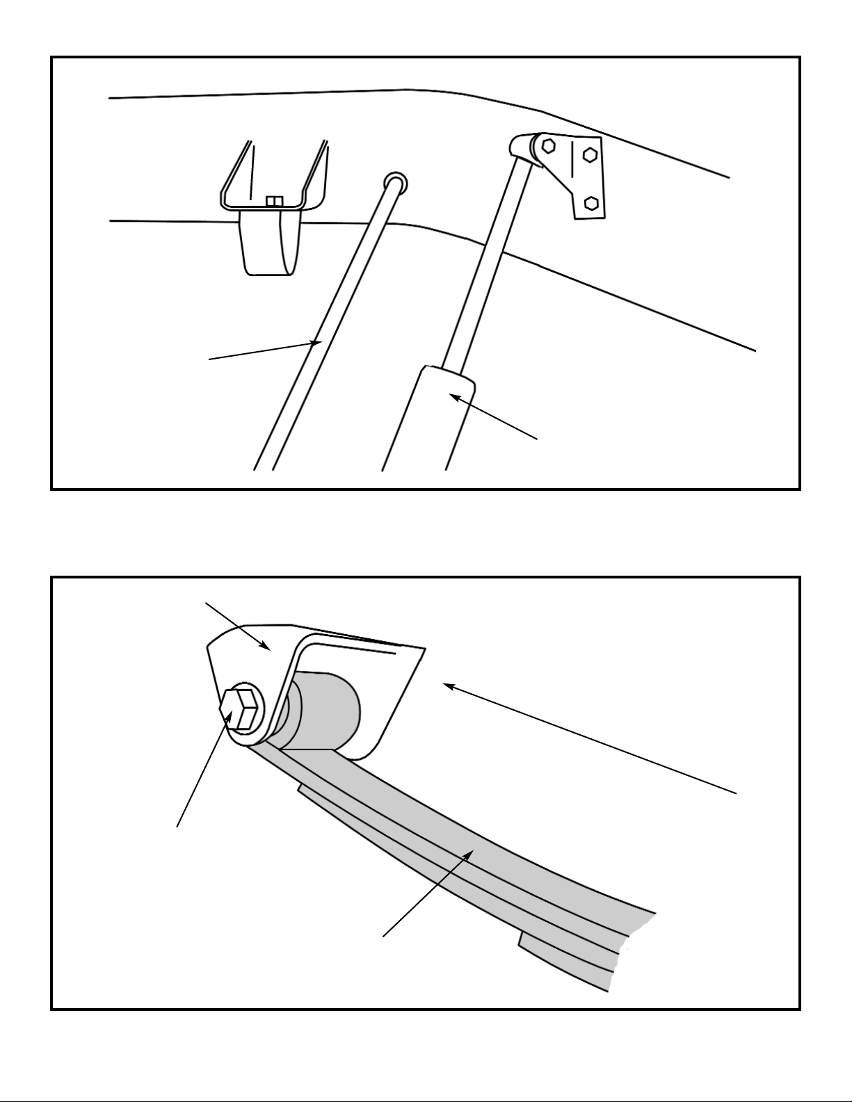
ILLUSTRATION # 1
STOCK FRONT SHOCK
ILLUSTRATION # 2
NEW FRONT
LEAF SPRING
FRONT OF VEHICLE
STOCK FRONT
SPRING HANGER
NEW FRONT SPRING
HANGER HARDWARE
STOCK FRONT
BRAKE HOSE
Page 7
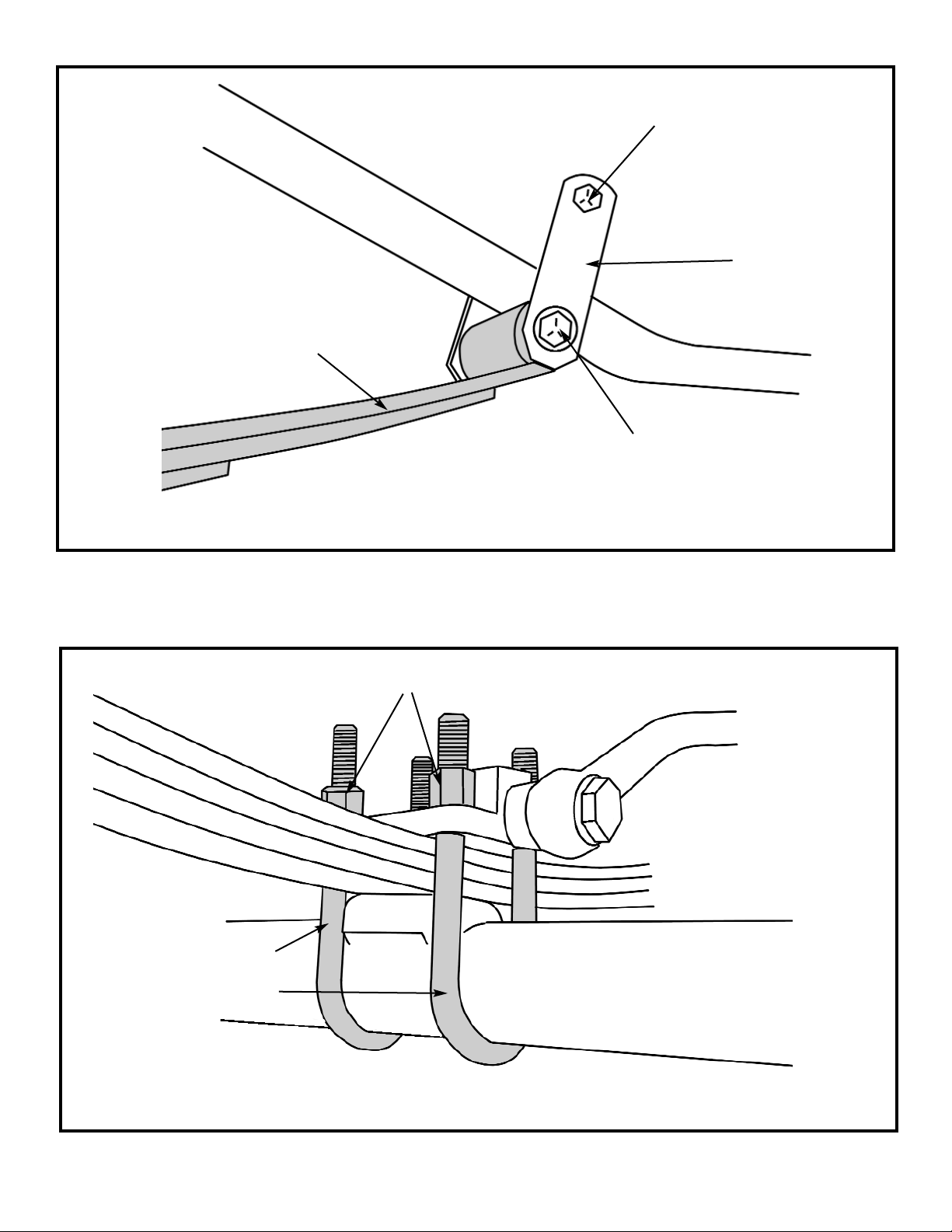
ILLUSTRATION # 3
ILLUSTRATION # 4
STOCK SPRING SHACKLE
HARDWARE
STOCK
SHACKLE
NEW FRONT LEAF
SPRING
NEW FRONT SPRING
SHACKLE HARDWARE
DRIVER SIDE
NEW 5/8” X 3” X 7 5/8”
U-BOLTS
NEW 5/8” U-BOLT HIGH NUTS & WASHERS
Page 8
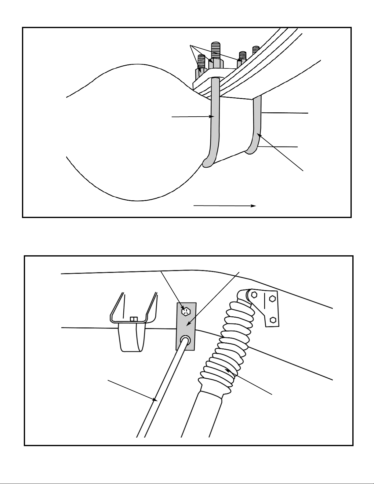
ILLUSTRATION # 5
ILLUSTRATION # 6
PASSENGER SIDE OF VEHICLE
NEW 5/8” X 3 1/2” X 9 5/8”
U-BOLT
NEW FRONT BRAKELINE
RELOCATION BRACKET
NEW FRONT
SHOCK
NEW 5/8” X 3” X 7 5/8”
U-BOLT
NEW 5/8” U-BOLT HIGH NUTS & WASHERS
STOCK FRONT
BRAKE HOSE
NEW 5/16” X 1” BOLT & HARDWARE
Page 9
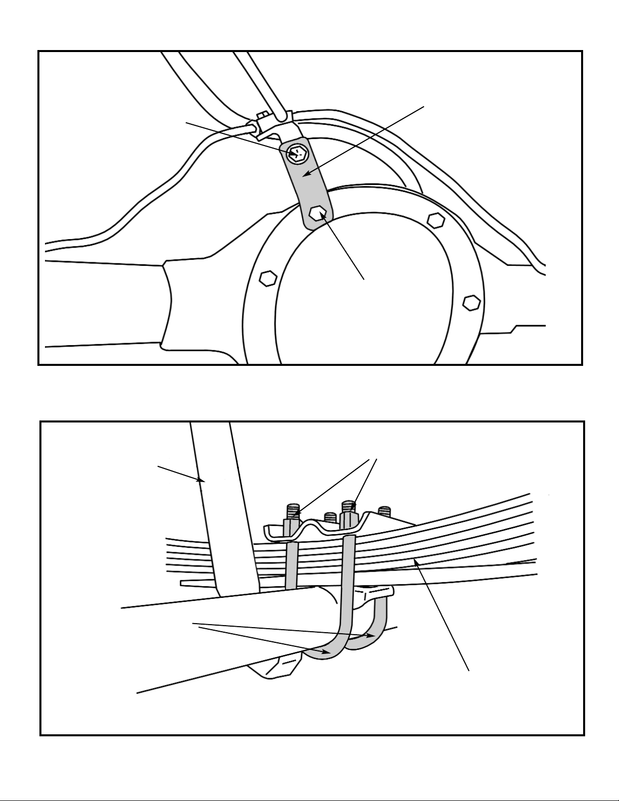
ILLUSTRATION # 7
ILLUSTRATION # 8
NEW REAR
LEAF SPRING
NEW 5/8” X 3 1/2” X 9 5/8”
U-BOLTS
NEW 5/16” X 1”
BOLT & HARDWARE
NEW REAR BRAKE LINE
RE-LOCATING BRACKET
STOCK HARDWARE
NEW 5/8” U-BOLT HIGH NUTS & WASHERS
NEW SHOCK
 Loading...