

TUFFCAT 2X1000, 2X1500, 3X1000, 3X1250, 2X1000P Owner's Manual
...
®
High Pressure Cleaning System
Standard and Pulsating
Owner’s Manual
Standard Models
2X1000, 2X1500, 3X1000, 3X1250
Pulsating Models
2X1000P, 3X1000P
SAVE THESE INSTRUCTIONS

High Pressure Cleaning System
ONE YEAR LIMITED WARRANTY
For one year from date of purchase, when the
High Pressure Cleaning System is maintained
and operated according to the instructions in the
SEND PREP AID to Cat Pumps, 1681 - 94th Lane
N.E., Minneapolis, MN 55449 or call 763-780-5440
for assistance.
owner’s manual, we will repair, free of charge,
any defects in material or workmanship.
Replacement of parts or accessories with non-
original items or servicing of unit other than that
This warranty does not cover repairs necessary
as a result of operator neglect or abuse or normal
specifically outlined in owner’s manual will VOID
THE WARRANTY.
wear. This cleaning system may be returned to
any Cat Pump distributor or directly to the factory .
TABLE OF CONTENTS
Features............................................................................................................................................................................3
Specifications..............................................................................................................................................................3
Important Safeguards
Rules for Safe Operation
Grounding Instructions
Ground-Fault Circuit-Interrupter
Extension Cords
Motor Reset
Accidental Submersion
...............................................................................................................................................................5
.......................................................................................................................................................................5
Assembly and Start-up.......................................................................................................................................6-7
Operation
Pressure Adjustment and Gauge Reading
Vari-Nozzle Adjustmen
Chemical Injection
Unit Shut-Down and Storage Instructions
Freeze Protection
Lubrication
Draining and Adding Oil ..................................................................................................................................................
........................................................................................................................................................................10
Maintenance of the Pump
Disassembly of the Discharge Valve Assembly
Disassembly of the Seal Assembly
Reassembly of the Seal Assembly
Reassembly of the Discharge Valve Assembly
Maintenance of the Crankcase, Unloader, Chemical Injector, Pulsator..................15
Cleaning System Parts List.............................................................................................................................16
Cleaning System Exploded View...............................................................................................................17
SF Pump Exploded View and Parts List..............................................................................................18
Unloader Exploded View and Parts List..............................................................................................19
Chemical Injector Exploded View and Parts List........................................................................19
Troubleshooting........................................................................................................................................................20-21
Standard and Optional Accessories.......................................................................................................22-23
.................................................................................................................................................4
...................................................................................................................................................4
.....................................................................................................................................5
...................................................................................................................................................5
....................................................................................................................8
t ...................................................................................................................................................8
............................................................................................................................................................9
.....................................................................................................................9
.............................................................................................................................................................10
............................................................................................................11
................................................................................................................................12
.................................................................................................................................13
.............................................................................................................14
10
!!
▲ CAUTION ▲
READ AND FOLLOW ALL SAFETY RULES AND
INSTRUCTIONS BEFORE OPERATING THIS UNIT.
INSTRUCTIONS GIVEN THIS SYMBOL
!
▲
ARE FOR PERSONAL SAFETY.
BE SURE TO FOLLOW THEM.
2

FEATURES
®
SPECIFICATIONS
1. The proven dependability of the SF
ceramic plunger pump offering unequaled
performance life in its horsepower range.
2. A custom designed, industrial electric
motor featuring Thermal Overload
Protection with reset button and low amp
draw performance.
3. 35 foot electrical cord with Ground-Fault
Circuit-Interrupter (GFCI) protection for
maximum safety during operation.
4. A convenient pop-up cord wrap making
carrying and storing easy and neat.
5. Impact resistant, lightweight molded plastic case free of excess weight and bulk.
6. Easy to read, flat-mount, glycerine-filled
pressure gauge to monitor system operation and meet exact cleaning needs.
7. Adjustable pressure regulating unloader
to set and maintain system pressure for
various cleaning applications.
8. Adjustable downstream chemical injector
with inlet hose and chemical strainer.
MODEL 2X1000 and 2X1000P
Listed LR 91309
80U8
Flow......................................2.0 GPM (7.6 LM)
Pressure ..............................1000 PSI (70 Bar)
Horsepower...................................1.5 (1.5)
Voltage................110 to 115V, 60 HZ (110 to 115V, 60 HZ)
Maximum Amperage ......................15 (15)
Weight......................................60 lbs. (27.1 kg)
PUMP MODEL...................2LIDX20E
MODEL 2X1500
Flow......................................2.0 GPM (7.6 LM)
Pressure ..............................1500 PSI (105 Bar)
Horsepower...................................2.0 (2.0)
Voltage................110 to 115V, 60 HZ (110 to 115V, 60 HZ)
Maximum Amperage ......................20 (20)
Weight......................................73 lbs. (33.2 kg)
PUMP MODEL...................2LIDX20E
MODEL 3X1000 and 3X1000P
Flow......................................3.0 GPM (11.4 LM)
Pressure ..............................1000 PSI (70 Bar)
Horsepower...................................2.0 (2.0)
Voltage................110 to 115V, 60 HZ (110 to 115V, 60 HZ)
Maximum Amperage ......................20 (20)
Weight......................................73 lbs. (33.2 kg)
PUMP MODEL...................2LIDX30E
9. Shut-off spray gun with molded extension
and quick coupling allows easy assembly
and quick changes to many optional
accessories.
10.Vari-Nozzle with extension, featuring
adjustable spray angle and high/low pressure settings for chemical application and
pressure cleaning flexibility.
11.30 foot, 3/8 inch, wire braid, nonmarking
high pressure hose with swivel and quick
disconnect for convenience in assembly
and operation.
12.Safety By-Pass hose with Thermo Valve
to minimize excessive liquid heat build-up.
Note: 100V, 50HZ, 60HZ available upon request.
Flow......................................2.4 GPM (9.0 LM)
Pressure ..............................1000 PSI (70 Bar)
Horsepower...................................2.0 (2.0)
Voltage...........................220V, 50 HZ (220 V, 50 HZ)
Maximum Amperage ...................10.2 (10.2)
Weight......................................73 lbs. (33.2 kg)
PUMP MODEL...................2LIDX30E
COMMON SPECIFICATIONS
Inlet *Pressure.......Flooded to 40 PSI (Fld to 3 BAR)
Max. **Liquid Temperature.......140°F (60°C)
Pump Oil Capacity....................11 oz. (0.35 L)
Hose Length...............................30 ft. (9.1M)
Cord Length (w/GFCI)............... 35 ft. (10.7M)
Wand Length .............................36 in. (91 cm)
Dimensions...........21.75x17.0x9.62" (553x432x244mm)
*Contact factory for information on optional inlet suction kit
**or high temperature version.
MODEL 3X1250
3
IMPORTANT SAFEGUARDS
WARNING - When using this product basic
precautions should always be followed,
including the following:
IMPORTANT: This manual should be read
and understood thoroughly before assembly
and operation of this High Pressure Cleaning
System. Keep this manual available for
future reference in servicing or ordering parts
or accessories.
Failure to follow basic safety rules and precautions could result in serious injury, shock
or fire.
RULES FOR SAFE OPERATION
!
▲ WARNING ▲
Risk of shock or electrocution.
●
Connect only to
properly grounded
outlet.
●
Do not remove
ground pin or use
cheater.
●
Know how to stop the product and bleed pressures
quickly. Be thoroughly familiar with the controls.
●
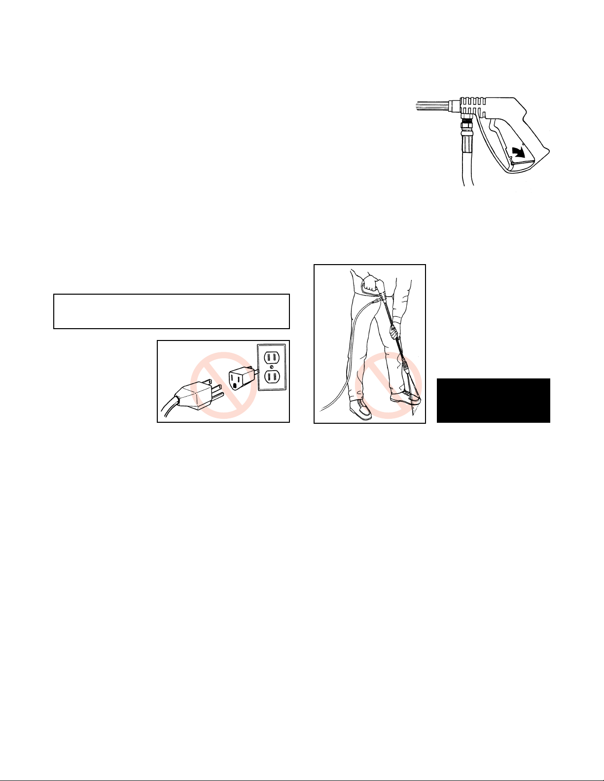
Do not overreach or stand on unstable support.
●
Keep good footing and balance at all times.
●
Do not use extension cords unless plugged into a
GFCI protected outlet and cord meets specifications
shown under “Extension Cords” in this manual.
●
Keep all connections dry and off ground.
●
Inspect electric cord before using and do not use if
damaged.
●
Do not spray at electrical areas.
●
Do not touch plug with wet hands.
●
This product is provided with a Ground-Fault
Circuit-Interrupter built into the power cord plug. If
replacement of the plug or cord is needed, use only
identical replacement parts.
●
Do not modify electric outlet. Have a qualified
electrician install the properly grounded outlet.
●
Unplug cord from receptacle before disconnecting
cleaning system from extension cord.
●
Keep operating area clear of all persons.
●
Never leave unit unattended while running.
!
●
To reduce the risk of injury, close supervision is
necessary when a product is used near children.
●
Stay alert - watch
what you are doing.
●
Engage safety lock on gun
trigger when not spraying.
●
Do not place hand over end of
nozzle, injury will result.
●
Do not remove nozzle guard.
●
Do not lift or pull unit by
pop-up cord wrap.
●
Do not operate the product when fatigued or
LOCK
under the influence of alcohol or drugs.
●
Do not spray at people or animals.
●
WARNING
Risk of injection or
injury - Do not direct
discharge stream at
persons.
●
Follow the maintenance
instructions specified in
the manual.
SAVE THESE
INSTRUCTIONS
In case of accidental injection with water,
contact physician.
GROUNDING INSTRUCTIONS
This product must be grounded. If it should
malfunction or break down, grounding provides a path of least resistance for electrical
current to reduce the risk of electric shock.
This product is equipped with a cord having
an equipment-grounding conductor and a
grounding plug. The plug must be plugged
into an appropriate outlet that is properly
installed and grounded in accordance with all
local codes and ordinances.
DANGER: Improper connection of the equipment-grounding conductor can result in a
risk of electrocution. Check with a qualified
4

electrician or service person if you are in
doubt as to whether the outlet is properly
grounded. Do not modify the plug provided
with the product—if it will not fit the outlet,
have a proper outlet installed by a qualified
electrician. Do not use any type of adapter
with this product.
GROUND-FAULT
CIRCUIT-INTERRUPTER
PROTECTION
This pressure washer is provided with a
GROUND-FAULT CIRCUIT-INTERRUPTER
(GFCI) built into the plug of the power supply
cord. This device provides additional protection from the risk of electric shock. Should
replacement of the plug or cord become necessary, use only identical replacement parts
that include GFCI protection.
If the GFCI is not the AUTOMATIC RESET
TYPE, it must be manually TESTED and
RESET each time the cleaning system is
plugged in. Press firmly to assure internal
spring activates switch. Push “test” then push
“reset”. Motor will not start if GFCI does not
reset. Check circuit
breakers or outlet.
If circuit breaker is
not tripped and
unit will not reset,
contact local
service center.
RESET
not in use". Use only extension cords having
an electrical rating not less than the rating of
the product. Do not use damaged extension
cords. Examine extension cord before using
and replace if damaged. Do not abuse extension cord and do not yank on any cord to disconnect. Keep cord away from heat and sharp
edges. Always disconnect the extension cord
from the receptacle before disconnecting the
product from the extension cord.
Extension Cord Length
Model up to 50 feet 50 to 100 feet
2X1000 14 AWG 12 AWG
2X1500 12 AWG 10 AWG
3X1000 12 AWG 10 AWG
3X1250 14 AWG 12 AWG
Extension cords are not recommended unless
they are plugged into a ground-fault circuitinterrupter found in circuit boxes or protected
outlet receptacles.
MOTOR RESET
This cleaning system has a motor reset button
in the event the motor overheats or overloads.
If the motor stalls turn the power switch to
OFF and unplug. Follow the guidelines under
“TROUBLESHOOTING” to determine the
cause of the motor shutdown. A plastic extension inserted into the reset hole on the side of
the case will initiate motor operation. TEST
AND RESET THE GFCI BEFORE TURNING
THE UNIT “ON”.
EXTENSION CORDS
!!
▲ WARNING ▲
To reduce the risk of electrocution, keep all
connections dry and off the ground. Do not
touch plug with wet hands.
Use only 3-wire extension cords that have
3-prong grounding-type plugs and 3-pole cord
connectors that accept the plug from the product. Use only extension cords that are intended for outdoor use. The extension cords are
identified by a marking “Acceptable for use
with outdoor appliances; store indoors while
RESET
ACCIDENTAL SUBMERSION
The molded case of this cleaning system is not
watertight. In case of accidental submersion,
case must be opened and all internal components thoroughly dried. Pump crankcase
should be drained and fresh oil added. See
“LUBRICA TION” for additional information.
5

ASSEMBLY AND START-UP
Remove the cleaning system from the carton
and inspect for damage or missing components. Keep box for storage or shipping unit
if service is required.
Place unit on a hard level surface and
visually verify that the oil level is at the dot in
center of gauge. The unit is shipped slightly
overfilled. Tip case to see air bubble before
operation.
Set unit on a hard level surface. Do not operate unit in tall grass or on other soft surface
that would restrict air flow to and from the
bottom of the case.
AIR FLOW
Attach the high pressure hose quick-disconnect to the discharge nipple on the top of the
case by pulling back the collar and pressing
over the nipple. Push down until it snaps into
position.
CAUTION
Lack of proper lubrication will result in
severe damage to pump. Visually check oil
before each use.
Be sure the power switch is in the “OFF”
position.
NOTE
When attaching accessories to the inlet
connection or chemical injector, some
movement may be noticeable. Each connection is o-ring sealed and the movement
is normal.
6
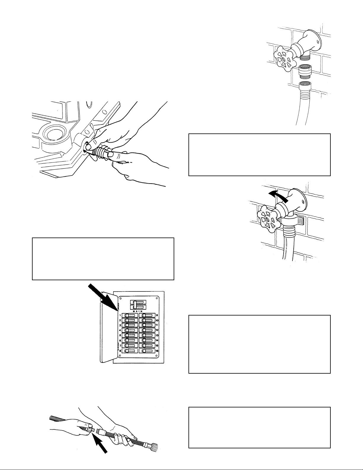
Attach a garden hose to the inlet fitting on the
side of the case. Check for the gasket and
screen in the fitting. The gasket assures a
good seal and the screen keeps debris from
entering the pump. CLEAN THIS SCREEN
periodically to avoid restricting liquid to the
pump. Inlet line must be a minimum of 1/2".
Be certain the inlet water supply is sufficient
before operating unit.
Uncoil the power cord and connect to a properly grounded receptacle. Voltage should be
between 110 and 115 to avoid stalling or
overloading motor. (15 amp for 1.5 H.P.,
20 amp for 2.0 H.P.)
CAUTION
2 H.P. Model must be plugged into an
outlet that is rated for 20 amps or greater
or the circuit breaker will trip.
15 amp
2X1000
20 amp
2X1500
3X1000
3X1250
Attach Vari-Nozzle with extension to gun with
extension. Snap Vari-Nozzle fitting into
extended hex collar on gun extension and
thread on hand tight.
Remove the
BACK FLOW
FAUCET
PREVENTER
from the owner’s
manual plastic
bag. Thread
female end of
preventer onto
BACK FLOW
PREVENTER
water supply
faucet. Then
thread garden
hose onto
GARDEN
HOSE
preventer.
CAUTION
Be certain to install the BACK FLOW
PREVENTER to prevent chemicals or soap
from flowing back into the supply line.
Turn inlet
water supply to
OPEN
the unit to full
open. Inlet water
temperature
should not
exceed the
maximum listed
in specifications.
Bleed air from system by triggering gun. With
adequate water pressure, unit should prime
within one minute. Trigger the gun with the
Vari-Nozzle in the (forward) low pressure
position to speed the priming.
CAUTION
If the unit is run with an inadequate inlet
water supply the unit will cavitate.
Cavitation causes the pump to operate
loudly, vibrate and cause damage to
the pump.
Flip power switch from “OFF” to “ON”.
Then trigger gun to assure all air is bled from
system.
CAUTION
NEVER leave unit unattended in by-pass
(with trigger gun shut off) for prolonged
periods.
7
OPERATION
PRESSURE ADJUSTMENT AND
GAUGE READING
Before using the cleaning system, the operating pressure must be set. The cleaning
system is equipped with a pressure gauge
for setting and monitoring system pressure.
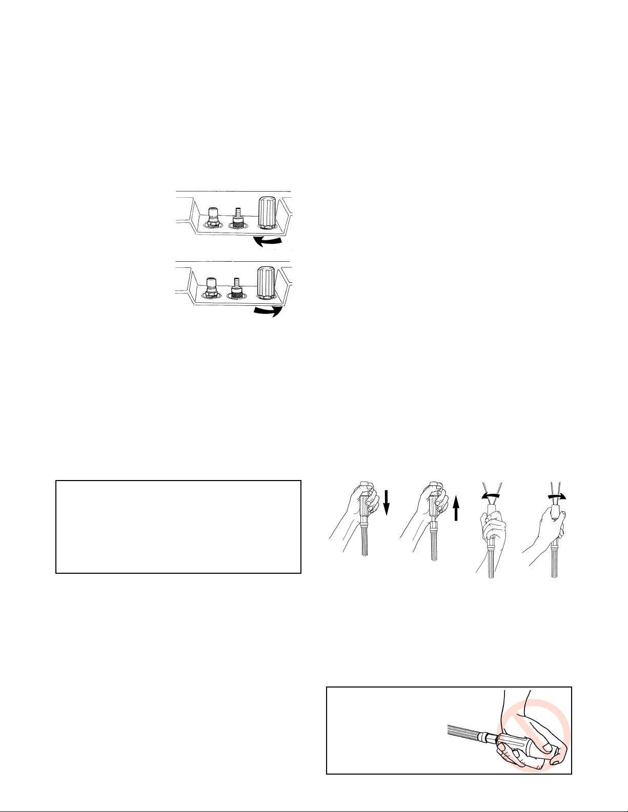
To set or adjust
pressure, rotate the
unloader adjustment
knob, marked “PSI”
on the top of the
case clockwise to
increase pressure
and counterclockwise to decrease
pressure. Make all
adjustments with the gun off (trigger
released). Adjust unloader 1/2 turn, squeeze
trigger and read pressure. If operating pressure has not been reached, repeat until
desired pressure is reached. Do not exceed
the maximum operating pressure listed in
specifications. Be certain to use only the
Vari-Nozzle provided with cleaning system or
replacement nozzle sized for the flow and
pressure of unit.
several times and check reading. If pressure
still has not dropped shut the unit off and consult “TROUBLESHOOTING”. For safety and
optimum life, operation in by-pass should not
exceed 6 minutes.The cleaning system is
equipped with an internal by-pass hose and
Thermo Valve. The Thermo Valve will sense
the rise in liquid temperature as a result of
running the unit in by-pass and bleed a small
amount of heated water from the bottom of
the case. Cool inlet water will fill the line and
protect the pump from overheating.
Prolonged operation in by-pass at high
pressure may result in damage to the pump
or the unloader. Turn system “OFF” during
prolonged periods of nonuse.
VARI-NOZZLE ADJUSTMENT
This unit is equipped with a multi-function
nozzle. The Vari-Nozzle changes from high
pressure (back position) to low pressure
(forward position) with an easy push-pull
motion. Changing from high to low pressure
permits the the low pressure adjustable chemical injector to begin drawing chemical into the
system. When chemical is no longer needed,
CAUTION
The maximum operating pressure of your
cleaning system has been secured at the
factory with a Locking Collar . Tampering or
removal of the Locking Collar on the
unloader valve will VOID THE WARRANTY.
Check your gauge while setting pressure
and periodically during operation. Changes
in pressure will warn you of wear or improper
operating conditions. If maximum pressure
cannot be reached or pressure drops after
prolonged use, it is most likely due to a worn
nozzle or lack of sufficient inlet water to the
unit. Consult “TROUBLESHOOTING” or call
your local service center.
When unit is running but in by-pass (gun off,
trigger released) pressure should drop to
approximately 100 PSI. If the pressure reading on the gauge does not drop, trigger gun
HIGH
PRESSURE
LOW
PRESSURE
WIDE
SPRAY
NARROW
SPRAY
return to high pressure (back position). The
Vari-Nozzle will also rotate right to left to adjust
from a 0° to 60° spray angle for desired cleaning needs. Make high to low pressure adjust-
ments with gun off or trigger released.
!!
▲ WARNING ▲
Do not place hand
over end of nozzle
while spraying or
adjusting nozzle.
8
 Loading...