

Tuff TNT-503021E, TNT-503531E, TNT-603531E, TNT-503061E, TNT-503021E/G Operator's Manual
...
TNT
OPERATOR’S MANUAL
■ TNT-503021E ■ TNT-503531E ■ TNT-603531E ■ TNT-503061E
■ TNT-503021E/G ■ TNT-503531EG ■ TNT-603531E/G ■ TNT-503061E/G
TUFF PRESSURE WASHERS ■ 659 Randall Wobbe Ln. ■ Sprindale, AZ 72764 ■ USA
For technical assistance or the TUFF Dealer nearest you, call 1-800-772-8833.

2
CONTENTS
Introduction...................................................................................................................................3
Important Safety Information.....................................................................................................3, 5
Component Identification ..............................................................................................................4
Pre-Operation Check ....................................................................................................................5
Set-Up Procedures ....................................................................................................................5-6
Operating Instructions...................................................................................................................6
General Washing T echniques........................................................................................................6
Shut Down Procedures.................................................................................................................6
How T o Use The Detergent Injector ..............................................................................................7
Prev entative Maintenance.............................................................................................................8
Maintenance and Service ..........................................................................................................8-9
Exploded Vie w, Left Side.............................................................................................................10
Exploded Vie w, Right Side ..........................................................................................................11
Parts List................................................................................................................................12-14
Float Tank Assembly, Exploded Vie w and P arts List ...................................................................15
Control Panel, Exploded Vie w.....................................................................................................16
Control Panel, Parts List .............................................................................................................17
Burner Assembly and Parts List..................................................................................................18
Hose and Spray Gun Assemb ly and Parts List ...........................................................................19
Troubleshooting .....................................................................................................................20-23
Maintenance Chart .....................................................................................................................24
Oil Change Record .....................................................................................................................24
Warranty .....................................................................................................................................25
Model Number ______________________________
Serial Number ______________________________
Date of Purchase ____________________________
The model and serial numbers will be found on a decal attached to
the pressure washer. You should record both serial number and
date of purchase and keep in a safe place f or future reference.
TUFF TNT Manual • Form #XX-XXXX • Revised 7/01

TNT SERIES PRESSURE W ASHER
WARNING
OPERAT OR’S MANUAL
3
INTRODUCTION
Thank you for purchasing a TNT Pressure Washer.
This manual covers the operation and maintenance of
the TNT -503021E, TNT -503021E/G, TNT -503531E, TNT 503531E/G, TNT-603531E, TNT-603531E/G, TNT503061E and TNT-503061E/G washers. All information
in this manual is based on the latest product information
available at the time of printing.
Landa, Inc. reserves the right to make changes at any
time without incurring any obligation.
The TNT Series was designed for maximum
use of 8 hours per day, 5 days per week.
Owner/User Responsibility:
The owner and/or user must have an understanding of
the manufacturer’ s oper ating instructions and warnings
before using this Landa pressure washer . W arning information should be emphasized and understood. If the operator is not fluent in English, the manufacturer’ s instructions and warnings shall be read to and discussed with
the operator in the operator’s native language by the
purchaser/owner, making sure that the operator comprehends its contents.
Owner and/or user must study and maintain for future
reference the manufacturers’ instructions.
This manual should be considered a permanent
part of the machine and should remain with it if
machine is resold.
When ordering parts, please specify model and
serial number .
IMPORTANT SAFETY
INFORMATION
WARNING: When using this product basic precautions
should always be follo wed, inc luding the following:
CAUTION
WARNING
READ OPERATOR’S
MANUAL
THOROUGHLY
PRIOR TO USE.
2. Know how to stop the machine and b leed pressures
quickly. Be thoroughly familiar with the controls.
3. Stay alert — watch what you are doing.
CAUTION: To reduce the risk of
injury, read operating instructions carefully before using.
1. Read the owner’s man ual thoroughly . Failure to follo w instructions could cause a malfunction
of the machine and result in
death, serious bodily injury and/
or property damage.
4. All installations must comply with local codes. Contact your electrician, plumber, utility compan y or the
selling distributor for specific details.
WARNING
WARNING: Risk of asphyxiation.
Use this product only in a well
ventilated area.
5. Avoid installing machines in
small areas or near exhaust
RISK OF
ASPHYXIATION.
USE THIS PRODUCT
ONLY IN A WELL
VENTILATED AREA.
fans. Exhaust contains poisonous carbon monoxide gas; exposure may cause loss of consciousness and may lead to
death. It also contains chemi-
cals known in certain quantities, to cause cancer,
birth defects, or other reproductive harm.
WARNING: Flammable liquids can
create fumes which can ignite,
causing property damage or severe injury .
CAUTION: Risk of fire. Do not add
RISK OF EXPLOSION:
DO NOT USE WITH
FLAMMABLE
LIQUIDS.
fuel when the product is operating.
6. Allow engine to cool for 2 minutes before refueling. If any fuel
is spilled, make sure the area
is dry before testing the spark plug or starting the engine. (Fire and/or explosion may occur if this is not done.)
Gasoline engines on mobile or portable equipment
shall be refueled:
(a) outdoors;
(b) with the engine on the equipment stopped;
(c) with no source of ignition, within 10 feet of the
dispensing point; and
(d) with an allowance made for expansion of the fuel
should the equipment be exposed to a higher
ambient temperature.
In an overfilling situation, additional precautions are
necessary to ensure that the situation is handled in
an safe manner.
WARNING: Risk of explosion – do not spray flammable liquids.
7. Do not place machine near flammable objects as
the engine is hot.
WARNING
WARNING: Risk of injection or severe injury to persons - Keep clear
of nozzle - Do not touch or direct
discharge stream at persons. This
machine is to be used only by
trained operators.
HIGH PRESSURE
STREAM CAN
PIERCE SKIN AND
TISSUES.
CAUTION: Hot discharge fluid. Do
not touch or direct discharge
stream at persons.
4
TNT SERIES PRESSURE W ASHER
COMPONENT IDENTIFICATION
OPERAT OR’S MANUAL
TNT SERIES PRESSURE W ASHER
OPERAT OR’S MANUAL
5
8. High pressure developed by these machines will cause
personal injury or equipment damage. Use caution
when operating. Do not direct discharge stream at
people, or sev ere injury or death will result.
WARNING
WARNING: High pressure spray
can cause paint chips or other
particles to become airborne and
fly at high speeds.
9. Eye safety devices, safety
USE PROTECTIVE
EYE WEAR
AND CLOTHING
WHEN OPERA TING
THIS EQUIPMENT.
clothing and foot protection
must be worn when using this
equipment.
10. Never make adjustments on
machine while it is in operation.
WARNING: Spray gun kicks back. Hold with both
hands.
11. Grip cleaning wand securely with both hands before
starting the cleaner. Failure to do this could result in
injury from a whipping wand.
12. Machines with spray gun should not be operated with
the spray gun in the off position for extensive periods of time as this may cause damage to the pump.
13. The best insurance against an accident is precaution and knowledge of the machine.
14. TUFF will not be liable for any changes made to our
standard machines, or any components not purchased from TUFF.
WARNING
WARNING: K eep wand, hose and
water spray away from electrical
wiring or fatal electric shock may
result.
15. Read engine safety instructions
KEEP WA TER
SPRA Y AWAY FROM
ELECTRICAL WIRING.
17. Inlet water must be cold and clean fresh water .
18. Use No. 1 or No. 2 Heating Oil (ASTM D306) only.
NEVER use gasoline in your fuel oil tank. Gasoline
is more combustible than fuel oil and could result in
a serious explosion. NEVER use cr ankcase or waste
oil in your burner. Fuel unit malfunction could result
from contamination.
19. Do not confuse gasoline and fuel oil tanks. Keep
proper fuel in proper tank.
20. Protect machine from freezing.
21. Be certain all quick coupler fittings are secured before using pressure washer .
22. Do not allow acids, caustic, or abrasive fluids to pass
through the pump.
provided.
16. Never run pump dry or leave
spray gun closed longer than 5
minutes.
23. T o reduce the risk of injury , close supervision is necessary when a product is used near children. Do not
allow children to operate the pressure washer . This
machine must be attended during operation.
24. Do not operate this product when fatigued or under
the influence of alcohol or drugs. K eep operating area
clear of all persons.
25. Protect discharge hose from vehicle traffic and sharp
objects. Inspect condition of high pressure hose before using or bodily injury may result.
26. Before disconnecting discharge hose from water outlet, turn burner off and open spray gun to allow water to cool below 100°F before stopping the machine.
Then open the spray gun to relie ve pressure. Failure
to properly cool down or maintain the heating coil
may result in a steam explosion.
27. TUFF will not be liable for any changes made to our
standard machines or any components not purchased from TUFF.
28. Do not overreach or stand on unstable support. K eep
good footing and balance at all times.
29. This machine must be attended during operation.
30.
CAUTION: Risk of injury. Disconnect battery
ground terminal before servicing.
PRE-OPERATION CHECK
❑ Pump oil (SAE 30W non-detergent oil, General)
❑ Cold water supply (6 gpm • 58" • 20 psi)
❑ Hose, wand, nozzle (nozzle size per serial plate)
❑ W ater filter (intact, non restrictive)
❑ Engine fuel (unleaded 86 or higher octane)
❑ Engine oil (SAE 10W30)
❑ Burner fuel (No. 1 home heating fuel or diesel)
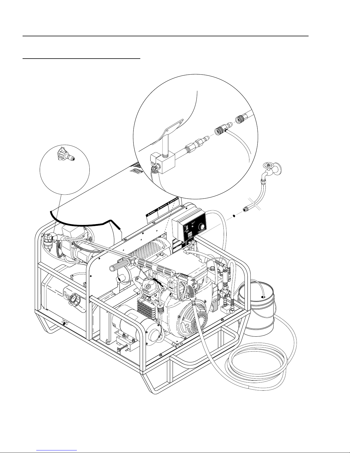
SET-UP PROCEDURES
This machine is intended for outdoor use only.
Machine must be stored indoors when not in use.
1. Attach a 5/8" water supply hose to inlet connector.
Minimum flow should be 6 or 10 gpm depending on
model of machine.
2. Attach high pressure hose to discharge nipple using
quick coupler. Lock coupler securely into place by
pulling back coupler collar and inserting it into discharge nipple, then pushing collar forward to loc k in
place.
3. Attach variable pressure control wand to spray gun
using teflon tape on threads to prevent leakage .
4. Attach swivel connector on discharge hose to spray
gun using teflon tape on threads.
6
TNT SERIES PRESSURE W ASHER
OPERAT OR’S MANUAL
5. Check engine and pump oil level by remo ving oil dipstick, making sure oil is on proper indicator marking.
Oil should be visible one half way up sight glass (SAE
30W non-detergent).
6. Fill red gasoline tank.
7. Fill green fuel tank. Do not confuse gasoline and fuel
oil (diesel) tanks. Keep proper fuel in proper tank.
8. Install proper battery making sure that the red cable
is attached to the positive terminal. Use a 12V Group
24 battery .
OPERATING INSTRUCTIONS
1. Read engine warning and operating instructions.
2. Turn on water at faucet. Check for water leaks; tighten
as needed.
3. Pull wand coupler collar back and insert desired pressure nozzle into wand coupler then secure by pushing coupler collar forward.
NOTE: V ariable pressure control w and handle must
be turned clockwise to enable water to flow out of
the high pressure nozzle.
4. Pull spray gun trigger to relieve pressure. Read engine manual provided and pull choke. Turn engine
switch to the START position and hold it there until
the engine starts. NOTE: Do not engage electric
starter for more than five (5) seconds at a time. If
engine fails to start, release the switch, pull spray
gun trigger to relieve pressure and wait ten seconds
before operating the start again. When the engine
starts, allow the engine switch to return to the ON
position. If the engine is to be started without the
battery , turn s witch to start position and pull starter
grip to start. Turn off choke.
CAUTION: Small engines may kick back. Do not hold
starter grip tightly in hand.
5. With the spray nozzle pointed aw ay from y ou or anybody else, press the trigger on the spray gun to obtain pressurized cold water spray.
6. For hot water , turn the b urner switch to ON when a
steady stream of water flows out of the spray gun.
Burner will now light automatically .
NOTE: Do not start machine with burner switch on.
7. T o apply detergent, place detergent pick-up tube into
a container of detergent and turn the detergent valve
counter clockwise (see page 4).
GENERAL W ASHING
TECHNIQUES
1. Hold spray nozzle approximately one foot from the
surface being cleaned. Spray at an angle to get under the material and lift it off.
2. When detergent is required for cleaning, start washing from the bottom and work up. Better detergent
economy and faster results will be obtained by allowing the chemical to set 5-10 minutes. After washing, rinse from the top down.
3. Cleaning heavy dir t or material away with a hard
stream of clear water is recommended before using
a cleaning agent.
SHUT DOWN PROCEDURES
1. Rinse all detergent lines with clean water, to remo ve
any soap residue.
2. T urn burner switch off and continue spraying, allo wing the water to cool to below 100°F.
3. Turn engine key switch off.
4. Turn off water supply.
5. Squeeze trigger on spray gun to relieve remaining
pressure.
6. Remove water supply hose.
7. In freezing conditions, disconnect water, dr ain float
tank and add a 50/50 mixture of anti-freeze. Start
the machine and squeeze trigger on spray gun to
allow the mixture to flow out of the wand. Now turn
off the engine. See winterizing procedure under Maintenance and Service.
WARNING
RISK OF
ASPHYXIATION.
USE THIS PRODUCT
ONL Y IN A WELL
VENTILA TED AREA.
causing severe nausea, fainting or poisoning. The
harmful elements may cause property damage or severe injury.
CAUTION: Do not allow pump to
run longer than 5 minutes without water. Disconnect all hoses to
allow water to drain.
With machine off, open spra y gun
to release pressure before removing discharge hose.
WARNING: Some detergents may
be harmful if inhaled or ingested,
TNT SERIES PRESSURE W ASHER
OPERAT OR’S MANUAL
7
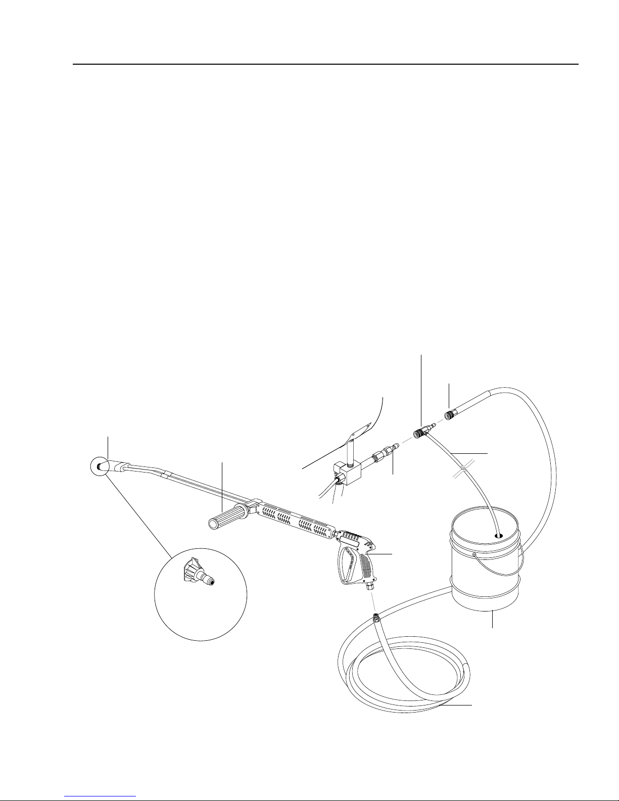
HOW TO USE THE OPTIONAL
DETERGENT INJECTOR
The machine can siphon and mix detergents with the use
of Landa's detergent injector kit.
1. Pull injector quick coupler collar back and secure on
discharge nipple. Injector valve body arrow should
point in direction of flow .
2. Connect high pressure hose to injector discharge
nipple securing quick coupler.
3. Start machine as outlined in Operating Instructions.
4. Place detergent pick-up tube into container of detergent.
5. Turn pressure control handle counterclockwise on
the variable pressure wand. This lowers the pressure by directing the water flow through the soap
nozzle and allows the detergent injector to siphon
soap.
6. Open spray gun. Water detergent ratio is approximately 15 to 1.
7. When you finish washing, rinse by simply turning
the variable pressure wand control handle cloc kwise
to increase pressure.
NOTE: The detergent injector will not siphon detergent with the water flowing through the high pressure nozzle at the end of the wand.
8. For clean up , place detergent c v tube into container
of clear water and follow steps 4 and 5 to prevent
detergent deposits from damaging the injector.
Detergent Injector
Quick
Coupler
Soap Nozzle
Variable Pressure
Control Wand Handle
High Pressure
Nozzle
Detergent
Pickup T ube
Discharge
Nipple
Spray Gun
Detergent
Bucket (Not
Included)
Detergent
Bucket (Not
Included)

8
TNT SERIES PRESSURE W ASHER
OPERAT OR’S MANUAL
PREVENTA TIVE MAINTENANCE
1. Check to see that water pump is properly lubricated.
2. Follow winterizing instructions to prevent freez e damage to pump and coils.
3. Always neutralize and flush detergent from system
after use.
4. If water is known to be high in mineral content, use a
water softener on your water system, or de-scale as
needed.
5. Do not allow acidic, caustic or abrasive fluids to be
pumped through system.
6. Alwa ys use high grade quality cleaning products.
7. Never run pump dry for extended periods of time.
8. Use clean fuel-kerosene, No. 1 fuel oil, or diesel.
Clean or replace fuel filter every 100 hours of operation. A void water contaminated fuel as it will damage
the fuel pump.
9. If machine is operated with smoky or eye burning
exhaust, coils will soot up, not letting water reach
maximum operating temperature.
10. Nev er allow water to be spray ed on or near the engine
or burner assembly or any electrical component.
11. Periodically delime coils as per instructions.
12. Check to see that engine is properly lubricated.
It is advisable, periodically, to visually inspect the burner.
Check air inlet to make sure it is not clogged or blocked.
Wipe off any oil spills and keep equipment clean and dry .
The flow of combustion and ventilating air to the b urner
must not be blocked or obstructed in any manner.
The area around the Landa washer should be kept clean
and free of combustible materials, gasoline and other
flammable vapors and liquids .
MAINTENANCE AND SERVICE
Unloader V alves:
Unloader valves are preset and tested at the f actory before shipping. Occasional adjustment of the unloader may
be necessary to maintain correct pressure.
Winterizing Procedure:
Damage due to freezing is not covered by w arranty. Adhere to the following cold weather procedures whene ver
the washer must be stored or operated outdoors under
freezing conditions.
During winter months, when temperatures drop below
32°F, protecting your machine against freezing is necessary . Store the machine in a heated room. If this is not
possible then mix a 50/50 solution of anti-freeze and
water in the float tank. Turn the engine on to siphon the
anti-freeze mixture through the machine. If compressed
air is available , an air fitting can be screwed into the float
tank by removing the float tank strainer and fitting. Then
inject the compressed air. Water will be blown out of the
machine when the trigger on the spray gun is opened.
High Limit Hot Water Thermostat:
For safety, each machine is equipped with a temperature sensitive high limit control switch. In the event that
the water should exceed its operating temperature, the
high limit control will turn the burner off until the water
cools then automatically reset itself. The thermostat sensor is located on the discharge side of the heating coil.
The thermostat control dial is located on the control panel.
Pumps:
Use only SAE 30 weight non-detergent oil. Change oil
after first 50 hours of use. Thereafter, change oil every
three months or at 500 hour intervals. Oil level should be
checked through use of dipstick found on top of pump,
or the red dot visible through the oil gauge window. Oil
should be maintained at that level.
Cleaning of Coils:
In alkaline water areas, lime deposits can accumulate
rapidly inside the heating coil. This growth is increased
by the extreme heat build up in the coil. The best pre ventative for liming conditions is to use high quality cleaning
detergents. In areas where alkaline water is an e xtreme
problem, periodic use of Landa Deliming Powder (C-Tech
Part #9-028008) will remove lime and other deposits
before coil becomes plugged. (See Deliming instructions
for use of Landa Deliming P owder.)
Deliming Coils:
Periodic flushing of coils or optional float tank is recommended.
Step 1 Fill a container with 4 gallons of water, then add
1 lb. of deliming powder . Mix thoroughly. Pour
mixture into float tank.
Step 2 Remove wand assembly from spra y gun and put
spray gun into float tank. Secure the trigger on
the spray gun into the open position.
Step 3 T urn engine on, allowing solution to be pumped
through coils back into the float tank. The solution should be allowed to circulate 2-4 hours or
until the color changes.
Step 4 After circulating solution, flush the entire sys-
tem with fresh water . Clean out float tank and
then reinstall wand assembly to spra y gun.
Removal of Soot and Heating Coil:
In the heating process, fuel residue in the form of soot
deposits may dev elop between the heating coil pipe and
block air flow which will aff ect burner combustion. When
soot has been detected on visual observation, the soot
on the coil must be washed off after following the coil
removal steps (See Coil Remov al on page 9).

TNT SERIES PRESSURE W ASHER
OPERAT OR’S MANUAL
9
Rupture Disk:
If pressure from pump or thermal expansion should exceed safe limits, the rupture disk will burst allo wing high
pressure to be discharged through hose to ground. When
disk ruptures it will need to be replaced.
Fuel:
Use clean fuel oil that is not contaminated with water
and debris. Replace fuel filter and drain tank every 100
hours of operation.
Use No.1 or No 2 Heating Oil (ASTM D306) only. NEVER
use gasoline in your burner fuel tank. Gasoline is more
combustible than fuel oil and could result in a serious explosion. NEVER use crankcase or waste oil in your burner .
Fuel unit malfunction could result from contamination.
Fuel Control System:
This machine utilizes a fuel solenoid valv e located on the
fuel pump to control the flow of fuel to the combustion chamber. The solenoid, which is normally closed, is activated b y
a flow switch when water flo ws through it. When the operator releases the trigger on the spray gun, the flow of water
through the flow switch stops, turning off the electrical current to the fuel solenoid.
The solenoid then closes, shutting off the supply of fuel to
the combustion chamber. Controlling the flow of fuel in this
way gives an instantaneous burn-or-no-burn situation,
thereby eliminating high and low water temperatures and
the combustion smoke normally associated with machines
incorporating a spray gun. Periodic inspection, to insure
that the fuel solenoid valve functions properly, is recommended. This can be done by operating the machine and
checking to see that the burner is not firing when the spray
gun is in the OFF position.
Fuel Pressure Adjustment:
T o control water temperature , adjust fuel pressure by turning the regulating pressure adjusting screw clockwise to
increase, counterclockwise to decrease. Do not exceed
200 psi. NO TE: When changing fuel pump, a bypass plug
must be installed in return port or fuel pump will not prime.
Air
Adjustment
Screw
Pressure
Gauge
Port
#7-0009
Fuel
Pump
Transformer
#7-20358
Air Band
Motor
#7-0005
Adjusting
Screw
#7-3753895
Cord Set
DC Electrodes Setting
Gap
1/8"
3/8"
1/2"
3/16"
Top Vie w Side View
Periodically Check Wiring Connections. If Necessary
To Adjust Electrodes, Use Diagram.
1/8"
Electrodes
2-7/8"
Nozzle
Adapter
Burner Nozzle:
Keep the tip free of surface deposits by wiping it with a
clean, solvent saturated cloth, being careful not to plug
or enlarge the nozzle. For maximum efficiency, replace
the nozzle each season.
Air Adjustment:
Machines are preset and performance tested at the factory - elevation 100'. A one-time initial correction for y our
location will pay off in economy, performance, and extended service life. If a smoky or eye-b urning exhaust is
being emitted from the stack, two things should be
checked. First, check the fuel to be certain that kerosene or No. 1 home heating fuel is being used. Next,
check the air adjustment on the burner.
Coil Removal:
Removal of coil because of freeze breakage , or to clean
soot from it can be done quickly and easily.
1. Disconnect hose from pump to inlet side of the coil.
2. Carefully disconnect the thermostat sensor making
sure you do not crimp the capillary tube.
3. Remove burner assembly from combustion chamber.
4. Remove the 3-3/8 bolts from each side of coil and
tank assembly (these bolts are used to fasten tank
to chassis).
5. Remove fittings connected to the 1/2" pipe nipples
from inlet and discharge sides of coil.
6. Remove top tank wrap, bend back insulation tabs
and fold back b lanket.
7. Remove bolts that hold down coil to bottom wrap.
8. Remove coil.
9. Replace or repair any insulation found to be torn or
broken.
10. Remove insulation retainer plates.
Coil Reinstallation:
Reinstall new or cleaned coil rev ersing Steps 9 through 1.

10
TNT SERIES PRESSURE W ASHER
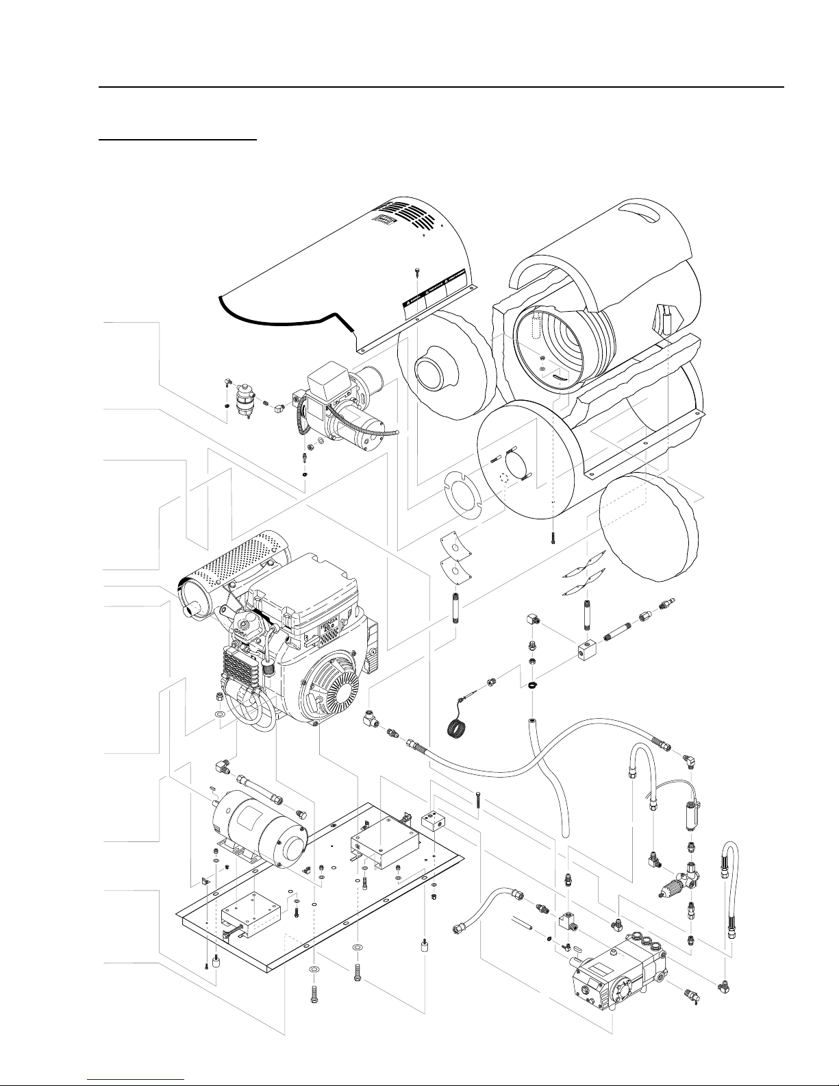
EXPLODED VIEW
LEFT SIDE
OPERAT OR’S MANUAL
TNT SERIES PRESSURE W ASHER
EXPLODED VIEW
RIGHT SIDE
OPERAT OR’S MANUAL
11

12
TNT SERIES PRESSURE W ASHER
EXPLODED VIEW
PARTS LIST
OPERAT OR’S MANUAL
ITEM P ART NO. DESCRIPTION QTY
1 95-07200010 Top Wrap, SS, PHW Series II 1
2 2-01104 Trim, 1/16" Black, /ft .6
3 90-1006 Bolt, 5/16" x 3/4" 4
4 2-0031 Elbow, 3/8" Street 1
5 90-1016 Bolt, 3/8" x 1", NC HH 15
6 7-01484 Insulation/Blanket - Die Cut
28" x 24" 1
7 7-01430 Insulation Blanket - No Foil,
24" x 57" 1
8 10-02011 Label, Use only Gasoline 1
9 10-02025A Label, Hot/Caliente 3
10 10-02028 Label, Warning-
Exposed Pulleys 2
11 7-0141 Insulation, Burner Head, w/Hole1
12 95-07121212 Coil Replacement Schedule 80
w/Mild Steel Wrap 1
13 95-07200012 Wrap, Bottom, Stainless Steel 1
14 7-0140 Insulation, Front Head, No Hole1
15 7-12484 Gasket, Standard - Large 1
16 7-0144 Gasket, Burner Plate 2
17 95-07121113 PHW/VNG Insulation
Retainer Plate 2
18 7-00030 Burner Assy, Beckett 12 Volt 1
7-58726 ▲ Electrode Rod & Insulator
Assy 1
7-21441 ▲ Solednoid, Valve, Fuel
12 V olt 1
7-21404 ▲ Wheel, Blower Fan 1
7-21405 ▲ Coupling, Fuel 1
7-0102 ▲ Nozzle, Burner 2.00, 90°, B 1
7-0103 ▲ Nozzle, Burner, 2.25, 90°, B 1
19 2-1022 Elbow, 1/4" Street 1
20 2-1002 Nipple, 1/4" Close 1
21 2-9905 Filter, Fuel/Oil H20 Separator 1
22 90-1019 Bolt, 3/8" x 1-3/4" Tap 3
23 2-9000 Clamp, Screw, #4 7
24 4-02100000 Hose, 1/4", Push-on /ft 14
25 2-1085 Hose Barb, 1/4" Barb x 1/4"
ML Pipe 1
26 2-00120 Nipple, 1/2" x 5" (4-2000, 4-3000,
5-3000, 5-3500) 1
2-00123 Nipple, 1/2"x5" Black Pipe
(4-4000) 2
ITEM P AR T NO. DESCRIPTION QTY
27 2-00101 Nipple, 1/2" x 3", Galv. 2
28 2-00241 Coupling, 1/2" x 3/8" Reducing 1
29 2-2007 Nipple, 3/8" x 3/8" NPT St Mal 1
2-20022 Nipple, 3/8" Female Fastener 1
30 2-0032 Elbow, 1/2" Street 1
31 2-90041 Clamp Screw #16 1
32 4-05088 Thermostat, General, 302° 1
33 4-02047725 Hose, 25" x 3/8", 100R2,
Pres Loop 1
34 4-02047716 Hose, 16" x 3/8", 100R2
Pres Loop 1
35 90-19959 Screw, 3/8" x 1" HX Wash 6
36 90-2001 Nut, 5/16" ESNA 4
37 90-4001 Washer, 5/16" Flat SAE 8
38 2-1089 Hose Barb, 1/4" Barb x 1/4"
Pipe, 90° 3
39 2-1037 Tee, 1/4" Branch Male 1
40 2-1076 Bushing, 1/2" x 1/4" Pipe 1
41 2-11080 Push-on 3/4" x 1/2" Male 1
42 4-02120000 Hose, 3/4", Push-on /ft. 1.3
43 5-3208 Unloader, AR, AL607 1
44 2-00101 Nipple, 1/2" x 4" Gal Sch 80 1
45 2-1060 Elbow, 1/2" JIC x 3/8" 90° 3
46 95-07101226 Discharge Block, 1/2" 1
47 90-1020 Bolt, 3/8" x 2", NC HH 2
48 95-07101216/B Block, Unloader, 3/8" x 3/8" Brass 1
49 4-02130050 Hose, Conduit 7/8" /ft. 2
50 10-02029 Label, Danger Cool Engine 1
51 2-0079 Swivel, 1/2" JIC x 3/8" Male 1
52 2-0051 Nipple, 1/2" JIC x 3/8" Pipe 1
53 90-1011 Bolt, 5/16" x 2", NC HH 4
54 2-10730 Elbow, 3/4" JIC x 1/2", 90° 1
55 2-1105 Swivel, 1/2" JIC Fem, Push-on 4
56 4-02110000 Hose, 1/2" Push-on /ft. 1.5
57 2-1062 Elbow, 1/2" JIC x 1/2" 90° 1
58 2-0053 Elbow, 1/2" JIC, 3/8" 90° 2
59 2-1035 Cross, 1/2" Female, Pipe 1
60 2-30082 Pump Protector, 1/2" PTP 1
61 2-1007 Nipple, 1/2" Hex 1
62 4-02100030 Inlet Hose, 30" Supply Water 1
63 4-02100013 Inlet Hose, 13" Supply Water 1

TNT SERIES PRESSURE W ASHER
EXPLODED VIEW
PARTS LIST (contin ued)
OPERAT OR’S MANUAL
13
ITEM P AR T NO. DESCRIPTION QTY
64 2-10712 Tee, 1/2" x 1/2" JIC 51# 1
65 2-1024 Elbow, 1/2" Street, Brass 1
66 6-0601 Generator, Winco (2000 watts) 1
66 6-0107 ▲ Cord, Molded, Royal, K1426,
14-3 1
67 2-0006 Nipple, 3/8" Hex 1
68 95-0712112 Rail, Pump or Generator
Combo (PHW/Skid) 2
69 95-07141110
70 90-10220 Bolt, 3/8" x 3-1/2", Tap 4
90-2020
90-2007
90-4002
71 2-0056 Elbow, 1/2" JIC, 3/8", 90°,
2-1101
72 2-1050 Plug, 1/2" JIC, Flare (VAN., 20 HP
73 10-99087 Label, Warning 1
74 2-11050 Swivel, 3/4" JIC FEM, Push-on 1
75 5-0107 Engine, Honda, GX340 QAE,
5-010722 Engine, Honda GX390 KQAE2
5-0309 Engine, Van. 16 HP ES No
5-0316 Engine, Van. 21 HP E/S
5-0105 Engine, Honda, GX340KQAP2
5-01093 Engine, Honda, GX620K1QB3,
76 76-807964 Muffler, Exhaust Skid,
76-808597 ▲ Muffler, Van. 21 HP 1
77-VHLM4 ▲ Muffler, (20 HP Honda) 1
77 95-07101149 Guard, Muffler, Vanguard 1
95-07101153 Guard, Van. 21 HP 1
95-071011491 ▲ Brace, Vangrd Muff. Bracket 2
78 5-511063 Bushing, H x 5/8" (Winco only) 1
Retainer, Pump Take Up, Plated
▲▲
▲ Nut, Cage 3/8" x 12 GA 9
▲▲
▲▲
▲ Nut, 3/8", HEXNC 4
▲▲
▲▲
▲ Washer, 3/8", SAE, Flat 50
▲▲
LBG (VAN., 20 HP Honda only) 1
▲▲
▲ Adaptor, 3/8" x 1/4" (20 HP
▲▲
Honda only) 1
Honda only) 1
E/S 11 HP (PGHW4-20321E) 1
13 HP E/S (4-30321E1) 1
Tank (5-30221E) 1
(5-35221E, 4-40221E) 1
11 HP, Pull Star t (4-20321) 1
20 HP, 20 Amp E/S (5-35321E) 1
16 HP Van. 1
2
ITEM P AR T NO. DESCRIPTION QTY
79 5-40403001 Pulley, BK30H (4-2000) GEN. 1
5-40403201 Pulley BK32H (4-4000, 5-3000,
5-3500) GEN 1
5-40403401 Pulley, BK34H (4-3000) GEN. 1
80 5-604022 Belt, BX 22 (all models) 1
81 5-531112 Bushing, P2, x 1" (all models) 1
82 5-407034 Pulley, 3 TB 34 (all models) 1
83 5-602033 Belt, AX33 (4-2000) 2
5-602035 Belt, AX35 (4-3000) 2
5-604032 Belt, BX32 (4-4000) 2
5-604036 Belt, BX36 (5-3000, 5-3500) 2
84 5-402084 Pulley, 2AK84 Pump (4-3000) 1
5-40509001 Pulley, 2BK90 H Pump
(5-3000, 5-3500) 1
5-402074 Pulley, 2AK74 H Pump (4-2000)1
5-40506701 Pulley, 2BK67H (4-4000) 1
85 5-12024 Bushing, H x 24 mm (all models)1
86 95-071410294 Belt Guard, Cover,
(4-2000, 4-3000) 1
95-071410293 Belt Guard, Cover,
(4-4000, 5-3000, 5-3500) 1
87 2-3408 Rupture Disk Assy, 8000 PSI 1
2-3480 Rupture Disk Replacement Only,
8000 PSI 1
88 95-071410274 Belt Guard, End Support,
Gen End
(16, 20, 21 HP Engines) 1
95-071410230 Belt Guard, End Support,
Gen End (9, 11, 13 HP Engines)1
89 2-10884 Diptube, 17" 2
90 95-071410273 Belt Guard, End Support,
Pump End (all models) 1
91 95-071410292 Face Plate, Belt Guard
(all models) 1
92 5-23042 Pump, General, TS1011L
(4-2000, 4-3000) 1
5-2306 Pump, General TS2021-L
(5-3000, 5-3500) 1
5-2320 Pump, General, T-9281 (4-4000)1
93 90-1996 Bolt, 3/8" x 3/4", NC HH, whiz 5
90-2020
▲ ▲
▲ Nut, Cage, 3/8" x 12 GA 9
▲ ▲

14
TNT SERIES PRESSURE W ASHER
EXPLODED VIEW
PARTS LIST (contin ued)
OPERAT OR’S MANUAL
ITEM P ART NO. DESCRIPTION QTY
94 90-10343 Bolt, 10 mm x 20 mm, HH 4
95 90-2002 Nut, 3/8" ESNA, NC 4
96 90-4002 Washer, 3/8", SAE, Flat 50
97 2-0115 Box, Battery, M-100 1
2-0117 Battery Box
(5-35321E, 4-40321E Only) 1
2-011500 ▲ Plate, Battery Box, Large,
Polypro 1
2-011700 ▲ Plate, Battery Box, Small
Polypro (5-35321E Only) 1
98 90-10051 Bolt, 5/16" x 1/2", Button Head 4
99 90-4008 ▲ Washer, 5/16", Lock,
Split Ring 4
100 90-4011 Washer, 5/16" Star 4
101 2-01011 Isolator, 5/16", F x F, 1" 4
102 95-07141043 Power Platform, PGHW (All) 1
103 90-4007 Washer, 3/8" x 1-1/2", Fender,
SAE 8
104 2-0108 Bumper Pad, Engine 16
105 95-07141004 Cage, PGHW 1
106 2-0104 Pad, Hard Rubber 8
107 2-10942 Swivel, 1/2" MP x 3/4" GHF
w/Strainer 1
108 95-07164010 Strap, MHP Fuel Tank w/Hole 8
ITEM P AR T NO. DESCRIPTION QTY
109 2-01167 Cap, Fuel Tank, Plastic
(Van., 20 HP Honda only) 2
110 2-011501 Tank, Fuel, 10 Gallon Poly,
Diesel, Green (4-4000, 5-3000,
5-3500) 1
111 2-011502 Tank, Fuel, 5 Gallon Poly,
Gasoline, Red (4-4000, 5-3000,
5-3500) 1
112 2-1088 Hose Barb 1/4" Barb x 1/8"
ML Pipe, 90° 1
114 2-01157 Cap, 14" w/Fuel Gauge,
(4-2000, 4-3000) 1
115 2-1088 Hose Barb 1/4" Barb x 1/8"
ML Pipe 90° 2
116 2-1052 Nipple, 1/2" JIC x 3/8" Pipe 1
117 10-020110 Label, Use only Kerosene 2
118 2-1060 Elbow 1/2" JIC x 3/8", 90° 1
119 95-07141045 Tank, Fuel, PGHW (4-2000,
4-3000) 1
120 2-00602 Adapter, 1/2" MJIC x 1/2"
FWPT, 90° 1
121 6-04174 Switch, Reed 1
122 2-4019 Gasket, Fuel Tank/ in. 24
123 6-021730 Switch, Flow MV60 1
▲ Not Shown

TNT SERIES PRESSURE W ASHER
OPERAT OR’S MANUAL
TNT FLOAT TANK ASSEMBLY & PARTS LIST (OPTIONAL)
EXPLODED VIEW
15
ITEM P AR T NO. DESCRIPTION QTY
1 2-01164 Tank, Plastic Universal 1
2 2-0147 Plug, Overflow 2
3 2-0151 Plug, Float Tank (Items 3 - 6) 1
4-02100000 1/4", Push-on Hose /inch 1
4 90-4030 Screw, 5/16" - 18 x 1-1/2" SS,
Button Socket 1
5 90-4032 Washer, 5/16", SS 1
6 90-4031 Nut, 5/16" - 18, Wing, SS 1
7 2-1062 Elbow, 1/2" JIC x 1/2", 90° 1
8 2-11041 Connector, 1/2" Anchor 1
9 4-02100013 Inlet Hose, 13" Supply Water 1
10 4-02100030 Inlet Hose, 30" Supply Water 1
ITEM P AR T NO. DESCRIPTION QTY
11 95-07121207 Lid and Hinges 1
12 2-3014 Valve, Fluidmaster 400A Float 2
13 2-10942 Swivel, 1/2" MP x 3/4" GHF
w/Strainer 1
14 2-1902 Strainer, Inlet Garden Hose 1
15 2-1024 Elbow, 1/2" Street, Brass 1
16 2-10712 Tee, 1/2" x 1/2" JIC #51 1
17 90-300210 Screw, #14 x 1", Tek, Blk 5
18 90-40002 Washer, 1/4", SAE, Blk 3
19 2-11080 Push-on, 3/4" x 1/2" Male 1
20 2-1906 Strainer, 1/2" Basket 1
16
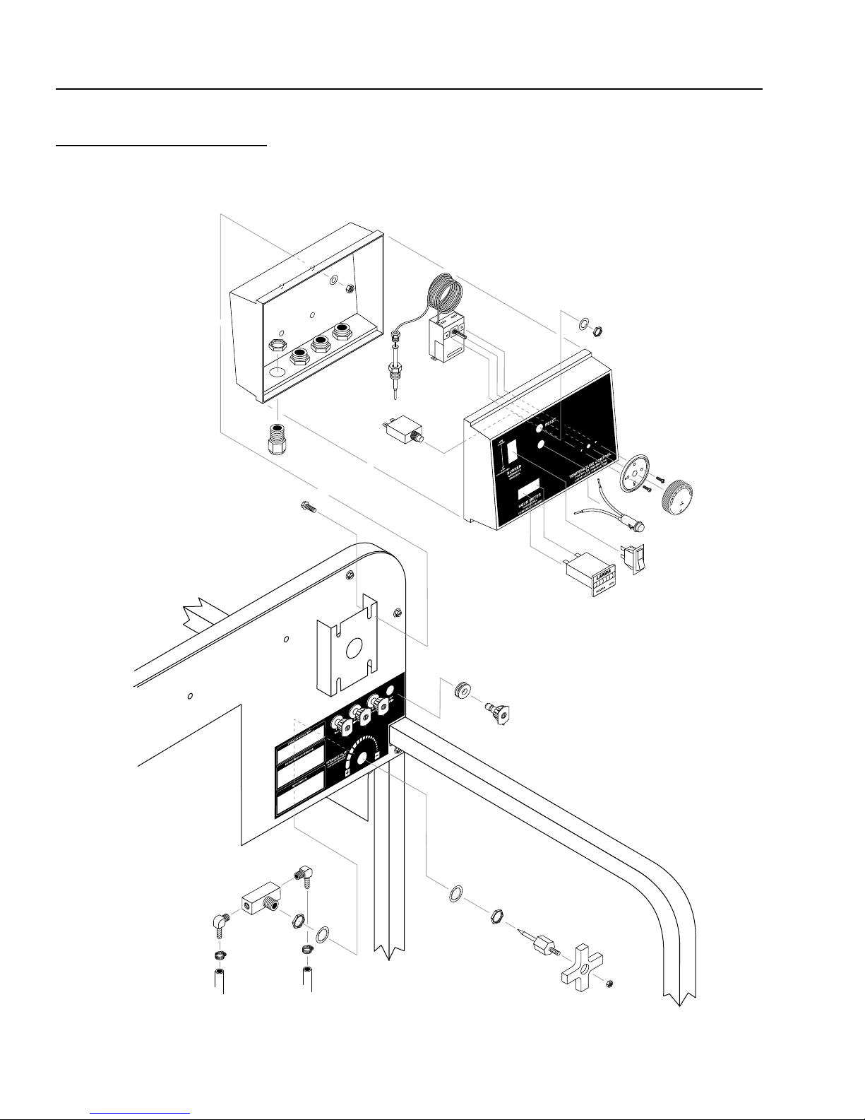
TNT SERIES PRESSURE W ASHER
TNT CONTROL PANEL
EXPLODED VIEW
OPERAT OR’S MANUAL

TNT SERIES PRESSURE W ASHER
TNT CONTROL PANEL
EXPLODED VIEW P ARTS LIST
OPERAT OR’S MANUAL
17
ITEM P AR T NO. DESCRIPTION QTY
1 10-07998 Label, PGHW Control Panel 1
2 2-0103 Grommet, 1/8" Rubber 4
3 2-0133 Screw, 10/32" x 1/2", Knob 2
4 2-10260 Elbow, 1/4" Street, 45° 1
5 2-1089 Hose Barb, 1/4" Barb x
1/4" Pipe 3
6 2-3015 Valve/Control, Metering 2
7 2-9000 Clamp, Screw #4 3
8 2-3028 Valve, Inline Metering MV250 1
9 4-050822 Hour Meter, ENM, 115Vac
50/60 Hz 1
10 4-02021226 Hose, Pressure Loop, 100R2,
26" x 1/4" (PGHW5-30221E,
5-35221E, 4-40221E) 1
4-02021236 Hose, Pressure Loop, 100R2 36"
x 1/4" (PGHW-4-20321E,
4-30321E) 1
11 95-071410460 Control Panel, PGHW 1
12 6-020251 Switch, Curvette 120V and
220V 1
13 2-1022 Elbow, 1/4" Steel 1
14 4-02080000 Tube, 1/4" X 1/2" Clr Vinyl /ft. 8
15 2-00260 Elbow, 1/4", Male, Pipe 1
16 4-02100000 Hose 1/4" /ft. 1
17 4-05088 Thermostat, General 302° 1
ITEM P AR T NO. DESCRIPTION QTY
18 4-12806000 Nozzle, 0006, Red (4-2000) 1
4-12806015 Nozzle, 1506, Yellow (4-2000) 1
4-12806025 Nozzle, 2506, Green (4-2000) 1
4-12806040 Nozzle, 4006, White (4-2000) 1
4-12804000 Nozzle, 0004, Red (4-3000) 1
4-12804015 Nozzle, 1504, Yellow (4-3000) 1
4-12804025 Nozzle, 2504, Green (4-3000) 1
4-12804040 Nozzle, 4004, White (4-3000) 1
4-12805500 Nozzle, 0005.5, Red (5-3000) 1
4-12805515 Nozzle, 1505.5, Yellow (5-3000)1
4-12805525 Nozzle, 2505.5, Green (5-3000)1
4-12805540 Nozzle, 4005.5, White (5-3000) 1
4-12805000 Nozzle, 0005, Red (5-3500) 1
4-12805015 Nozzle, 1505, Yellow (5-3500) 1
4-12805025 Nozzle, 2505, Green (5-3500) 1
4-12805040 Nozzle, 4005, White (5-3500) 1
4-01404000 Nozzle Only, 1/4" MEG-0004
SS (4-4000) 1
4-01404015 Nozzle Only, 1/4" MEG-1504
SS (4-4000) 1
4-01404025 Nozzle Only, 1/4" MEG-2504
SS (4-4000) 1
4-01404040 Nozzle Only, 1/4" MEG-4004
SS (4-4000) 1
19 2-20024 ▲ Nipple, 1/4" Female
(4-4000 only) 4
▲ Not Shown
18
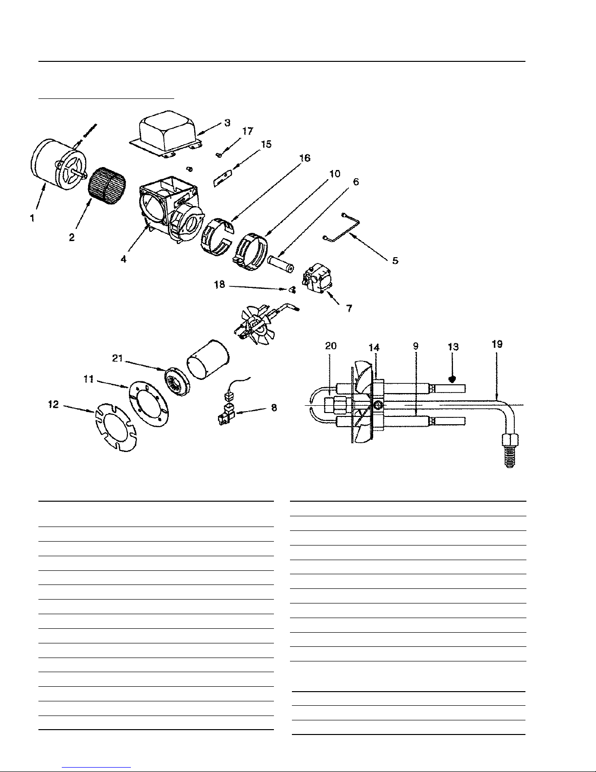
TNT SERIES PRESSURE W ASHER
BURNER ASSEMBLY
ALL MODELS
OPERAT OR’S MANUAL
ITEM PAR T NO. DESCRIPTION QTY
1 7-0005 Motor 1/5 HP 3450 RPM
Cap, 115V/230V 1
2 7-21854001 Fan, Burner 6" 1
3 7-20358 Transformer, Burner 115V 1
4 7-4725 Burner Housing 1
5 7-0020 Fuel Line, Copper 1
6 7-13279 Coupling, Fuel Pump to Motor 1
7 7-0009 Fuel Pump 1
8 7-0009611 Solenoid Kit w/115V Coil 1
9 7-13286 Electrode, Bur ner 2
10 7-2668-002 Air Adjustment Band, Outer 2
11 7-21526 Cast Flange 1
12 7-12484 Burner Gasket 2
13 7-12945 Buss Bar 2
7-14296 ▲ Nut, Gun Assembly 1
7-100418-003 ▲ Screw, Electrode Clamp 1
ITEM P AR T NO. DESCRIPTION QTY
14 7-1006750-001 Clamp, Electrodes 1
15 7-13392 Adjustment Plate, Gun Assembly 1
16 7-2669-002 Air Band, Inner 1
17 7-13045 Bolt, Transf ormer Hinge 2
7-13360 ▲ Bolt, Transf ormer Clip 1
7-1000689-001 ▲ Hold Down Clip, Transformer 1
18 7-13494 Brass Elbow, Fuel Pump 1
19 7-30540003 Gun Assembly, Complete 1
20 7-21913-001 Adapter, Nozzle 1
Machine Model Nozzle Fuel Burner 1
21 7-14160 Cone, Air, 4A 1
▲ Not Shown
MACHINE MODEL PART NO.BURNER NOZZLE QTY
PGHW4-2000 7-0126 2.25/80° 1
PGHW5-3000, 5-3500 7-0127 2.50/80° 1
PGHW4-3000, 4-4000 7-0125 2.00/80° 1
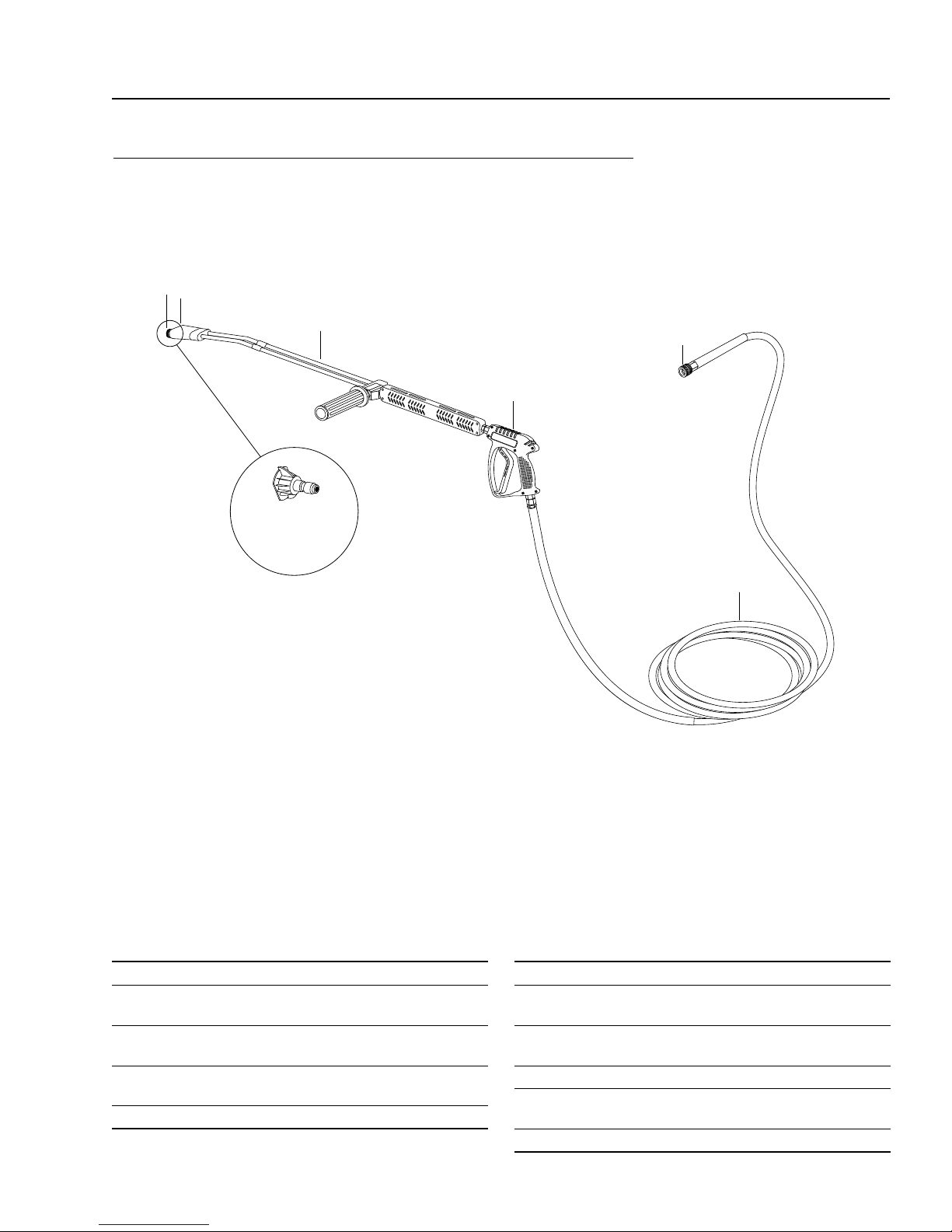
TNT SERIES PRESSURE W ASHER
TNT HOSE/SPRAY GUN ASSEMBLY & PARTS LIST
ALL MODELS
5
6
OPERAT OR’S MANUAL
19
4
3
1
2
ITEM P AR T NO. DESCRIPTION QTY
1 2-2002 Coupler, 3/8" Female 1
2 4-02083450 Hose, 50' x 3/8", 2 Wire,
8500 PSI 1
3 4-01226 Spray Gun, Shut-Off, 10 GPM @
4000 PSI, AL-A5 1
4 4-011134 Wand, VP, Molded Grip, 1/4"
(X-Series) 1
83-SSVPKIT Repair Kit, AL Stainless Seat 1
ITEM P AR T NO. DESCRIPTION QTY
5 2-2001 Coupler, 1/4" Male 1
2-20023 Coupler, 1/4" Female
(4-4000 only) 1
2-0003 ▲ Nipple, 1/4" Steel
(4-4000 only) 1
2-0119 ▲ O-Ring, Replacement Only 1
2-0132 ▲ Seal, 1/4" Replacement Only
(4-4000 Only) 1
6 4-06540 ▲ Nozzle, Soap, 1/8" Brass 1
▲ Not Shown

20
TNT SERIES PRESSURE W ASHER
TROUBLESHOOTING
PROBLEM POSSIBLE CAUSE SOLUTI ON
OPERAT OR’S MANUAL
LOW OPERATING
PRESSURE
Faulty pressure gauge Install new gauge.
Insufficient water supply Use larger supply hose; clean filter at water
inlet.
Old, worn or incorrec t spray nozzle Match nozzle number to machine and/or
replace with new nozzle.
Belt slippage Tighten or replace; use correct belt.
Plumbing or hose leak Check plumbing syste m for leaks. Retape
leaks with teflon tape.
Faulty or misadjusted unloader valve Adjust unloader for proper pres sure. Install
repair kit when needed.
Worn packing in pump Install new packing kit.
Fouled or dirty inl et or disch arge
valves in pump
Worn inlet or discharge valves Replace with valve kit.
Obstruction in s pray nozzle Remove obstruction.
Leaking pressure contr ol valve Rebuild or replace as needed.
Slow engine RPM Set engine speed at proper specificat ions.
Clean inlet and discharge valves.
BURNER WILL NOT
LIGHT
(continued on next
page)
Pump sucking air Check water supply and possibility of air
seepage.
Valves sticking Check and clean or replace if necessar y.
Unloader valve seat faulty Check and replace if necessar y.
Little or no fuel Fill tank with fuel.
Improper fuel or water in fuel Drain fuel tank and fill wi th proper fuel.
Clogged fuel line Clean or replace.
Plugged fuel filter Replace as needed.
Misadjusted burner air bands Readjust air bands for clean burn.
Little or no fuel press ure from fuel
pump
Faulty burner transformer Test transformer for proper arc between
Disconnected or shor t in elec tr ical
wiring
Increase fuel pressure t o speci ficati on and/or
replace fuel pump. Test with pressure gauge.
contacts. Replace as needed.
All wire contacts shoul d be clean and t ight.
No breaks in wire.

TNT SERIES PRESSURE W ASHER
OPERAT OR’S MANUAL
TROUBLESHOOTING
PROBLEM POSSIBLE CAUSE SOLUTION
21
BURNER WILL NOT
LIGHT
(continued from
previous page)
Flex coupling slipping on fuel pump
shaft or burner motor shaft
On-Off switch defective Check for electrical cu rrent reac hing burner
Heavy sooting on coil and burner can
cause interruption of ai r flow and
shorting of el ectr odes
Improper electrode setting Check and reset according to diagram in
Fuel not reaching combustion
chamber
Clogged burner nozzle Clean as required.
Thermostat faulty or slow engine
speed
Flow switch malfunction Remove, test for continuity and replace as
Flow solenoid malfunction Replace if needed.
Replace if needed.
assembly with burner switch on.
Clean as required.
Operator's Manual.
Check fuel pump for proper flow. Check
solenoid flow switch on machines withspray
gun control, for proper on-off fuel flow
control.
Increase engine RPM to increase voltage.
needed.
FLUCTUATING
PRESSURE
MACHINE SMOKES
Valves worn Check and replace if necessary.
Blockage in valve Check and replace if necessary.
Pump sucking air Check water supply and air seepage at joi nt s
in suction line.
Worn piston packing Check and replace if necessary.
Improper fuel or water in fuel Drain tank and replace contaminated fuel.
Improper air adjustment Readjust air bands on burner assembly.
Low fuel pressure Adjust fuel pump pressure to specif ications.
Plugged or dirt y burner nozz le Replace nozzle.
Faulty burner nozzle spray pattern Replace nozzle.
Heavy accumulation of soot on coils
and burner assembly
Misaligned electrode setting Realign electrodes to specific ations.
Obstruction in smoke stack Check for insulation blockage or other foreign
Low engine RPM Inc rease RPM.
Remove coils and burner assembly, clean
thoroughly.
objects.

22
TNT SERIES PRESSURE W ASHER
TROUBLESHOOTING
PROBLEM POSSIBLE CAUSE SOLUTION
OPERAT OR’S MANUAL
LOW WATER
TEMPERATURE
WATER
TEMPERATURE
TOO HOT
Improper fuel or water in fuel Replace with clean and proper fuel.
Low fuel pressure Increase fuel pressure.
Weak fuel pump Check fuel pump pressure. Replace pump if
needed.
Fuel filter par ti ally cl ogged Replace as needed.
Soot build-up on coils not allowing
heat transfer
Improper burner nozzle See specifications. (page 18)
Incoming water to machine warm or
hot
Fuel pump pressure too high See specifications for proper fuel pressur e.
Fuel pump defective Replace fuel pump.
Detergent line sucking air Tighten all clamps. Check detergent lines for
Defective temperature switch Replace.
Incorrect fuel nozzle si ze
Clean coils.
Lower incoming water temperature.
holes.
See specifications for proper fuel pressur e.
(page 18)
PUMP NOISY
PRESENCE OF
WATER IN OIL
WATER DRI PPI NG
FROM UNDER
PUMP
Insufficient water supplied
Restrict water flow Check nozzle for obstruction, proper size.
Air in suction line Check water supply and connections on
Broken or weak inlet or discharge
valve springs
Excessive matter in valves Check and clean if necessar y.
Worn bearings Check and replace if necessary.
Oil seal worn Check and replace if necessary.
High humidity in air Check and change oil twice as often.
Piston packing worn Check and replace if necessary.
O-Ring plunger retainer worn Check and replace if necessar y.
Cracked piston Check and replace if necessary.
Pump protector Lower water supply pressure. Do not run with
Check water G.P.M. to machine.
suction line.
Check and replace if necessary.
spray gun closed longer than 5 minutes.

TNT SERIES PRESSURE W ASHER
OPERAT OR’S MANUAL
TROUBLESHOOTING
PROBLEM POSSIBLE CAUSE SOLUTION
23
OIL DRIPPING
EXCESSIVE
VIBRATION IN
DELIVERY LINE
DETERGENT NOT
DRAWING
PUMP RUNNING
NORMALLY BUT
PRESSURE LOW ON
INST ALLATION
Oil seal worn Check and replace if neces sar y.
Irregular functioni ng of the valves Check and replace if necessary.
Air leak Tighten all clamps. Check chemical lines for
holes.
Restrictor i n float tank i s missing Replac e rest ri ctor. Check for proper ori fic e in
restrictor.
Filter screen on deterge nt sucti on
hose plugged
Dried up detergent plugging met eri ng
valve
High viscosity of detergent Dilute detergent to specif icat ions.
Hole in detergent line( s) Repair hole.
Low detergent level Add detergent, if needed.
Pump sucking air Check water supply and possibilit y of air
Valves sticking Check and clean or repl ace i f necess ar y.
Nozzle incorrectly sized
Clean or replace.
Disassemble and clean thoroughly.
seepage.
Check and replace if necessay (See serial
plate for proper size).
BURNER MOTOR
WILL NOT RUN
RELIEF VALVE
LEAKS WATER
Unloader valve seat faulty Check and replace if necessary.
Worn piston packing Check and replace if necessary.
Fuel pump seized Replace fuel pump.
Burner fan loose or misaligned Position correctly, tighten set screw.
Defective control switch Replace switch.
Loose wire Check and replace or tighten wiring.
Defective burner motor Replace motor.
Relief valve defective Replace or repair.

24
TNT SERIES PRESSURE W ASHER
OPERAT OR’S MANUAL
OIL CHANGE RECORD
Check pump oil level before first use of your new Power Washer. Change pump oil after first 50 hours and
every 3 months or 500 hours thereafter . Use SAE 30 weight oil, non-detergent.
Date Oil Ch ange d
Month/Day/Year
No. of Operating Hours
Since Last Oil Change
Brand Name and
Type of Oil (see above)
MAINTENANCE
Maintenance O per a t ion
Pump
Check Oil
Engine
Pump
Change Oil
Engine
Air Clea ner Check Clean
Spark Pl ug
Check Valve Clearance
Fuel Tank Filter
Water Filter/Clean
Every 8 Hrs
or Daily
X
Check
25 Hrs or
Weekly
X
50 Hrs or
Monthly
100 Hrs or
Yearly
X
X
X
Yearly
X
X
X

TNT SERIES PRESSURE WASHER
WARRANTY
TNT LIMITED NEW PRODUCT WARRANTY
PRESSURE W ASHERS
WHAT THIS WARRANTY COVERS
All TUFF PRESSURE WASHERS are warranted by TUFF to the original purchaser to be free from defects in materials and
workmanship under normal use, for the periods specified below . This Limited W arranty is subject to the e xclusions sho wn below ,
is calculated from the date of the original purchase, and applies to the original components only. Any parts replaced under this
warranty will assume the remainder of the part’s warranty period. In the case of defect, please return with a copy of your proof
of purchase, to the dealer from whom you purchased your pressure washer for possible warranty.
THREE YEAR PARTS AND NO LABOR WARRANTY:
Components manufactured by TUFF, such as frames, handles, coil wraps, float tanks, belt guards, and coils. Internal components on the oil-end of all pressure washer pumps.
NINETY DAYS MINIMUM ON PARTS AND NO LABOR WARRANTY:
All other components, excluding normal wear items as described below, will be warranted for ninety days on parts. Parts
warranty will be for ninety days regardless of the duration of the original component manufacturer’s warranty.
WARRANTY PROVIDED BY OTHER MANUFACTURERS:
Motors, generators, and engines, which are warranted by their respective manu facturers, are serviced through these manufacturers’ local authorized service centers. TUFF cannot provide warranty on these items.
WHAT THIS WARRANTY DOES NOT COVER
This warranty does not cover the following items:
1. Normal wear items, such as nozzles, guns, discharge hoses, wands, quick couplers, seals, filters, gaskets, O-rings,
packings, pistons, pump valve assemblies, strainers, belts, brushes, rupture disks, fuses, pump protectors.
2. Damage or malfunctions resulting from accidents, abuse, modifications, alterations, incorrect installation, improper
servicing, failure to follow manufacturer’s maintenance instructions, or use of the equipment beyond its stated usage
specifications as contained in the operator’s manual.
3. Damage due to freezing, chemical deterioration, scale buildup, rust, corrosion, or thermal expansion.
4. Damage to components from fluctuations in electrical or water supply.
5. Normal maintenance service, including adjustments, fuel system cleaning, and clearing of obstructions.
6. Transportation to service center, field labor charges, or freight damage.
WHAT YOU MUST DO TO OBTAIN WARRANTY SERVICE
In order to obtain warranty service on items warranted by TUFF, you must return the product to the dealer from whom you
purchased, freight prepaid, with proof of purchase, within the applicable warranty period. For warranty service on components
warranted by other manufacturers, the TUFF Dealer can help you obtain warranty service through these manufacturers’ local
authorized service centers.
LIMITATION OF LIABILITY
TUFF’S liability for special, incidental, or consequential damages is expressly disclaimed. In no event shall TUFF’S liability
exceed the purchase price of the product in question. TUFF makes e v ery effort to ensure that all illustrations and specifications
are correct, however, these do not imply a warranty that the product is merchantable or fit for a particular purpose, or that the
product will actually conform to the illustrations and specifications. THE W ARRANTY CONTAINED HEREIN IS IN LIEU OF ALL
OTHER WARRANTIES, EXPRESS OR IMPLIED, INCLUDING ANY IMPLIED WARRANTY OF FITNESS FOR A PARTICULAR PURPOSE. TUFF does not authorize any other party, including authorized Dealers, to make an y representation or prom-
ise on behalf of TUFF, or to modify the terms, conditions, or limitations in any way. It is the buyer’s responsibility to ensure that
the installation and use of TUFF products conforms to local codes. While TUFF attempts to assure that its products meet
national codes, it cannot be responsible for how the customer chooses to use or install the product.
TUFF PRESSURE WASHERS
659 Randall Wobbe Ln. • Springdale, AR 72764 • 1-800-772-8833

659 Randall W obbe Ln. • Springdale, AZ 72764 • 1-800-772-8833
Form #XX-XXXX • Revised 7/01 • Printed in U .S .A.
 Loading...