

Page 1
INSTALLATIO N MA NU AL
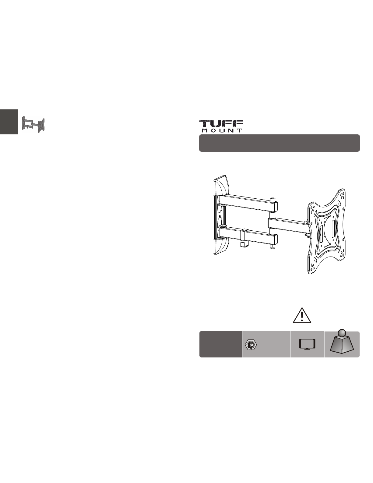
Full Motion LED, LCD TV Wall Mount
42"
MAX
CAU TION: D O NOT EXC EED
RATED L ISTED W EIGHT. SE RIOUS
INJ URY OR PRO PERTY DA MAGE
MAY OCC UR!
75x 75/10 0x100
200 x100/ 200x2 00
A2 0 07
20k g
(44 lbs)
RATE D
20k g
(44 lbs)
RATE D
FOR CUS TO MER SER VI CE CALL 8 55-44 9- 88 33 TU FF
Page 2
21
NOTE: R ea d the e nt ire ins tr uct io n manua l be for e yo u st art i ns talla ti on an d as sembl y.
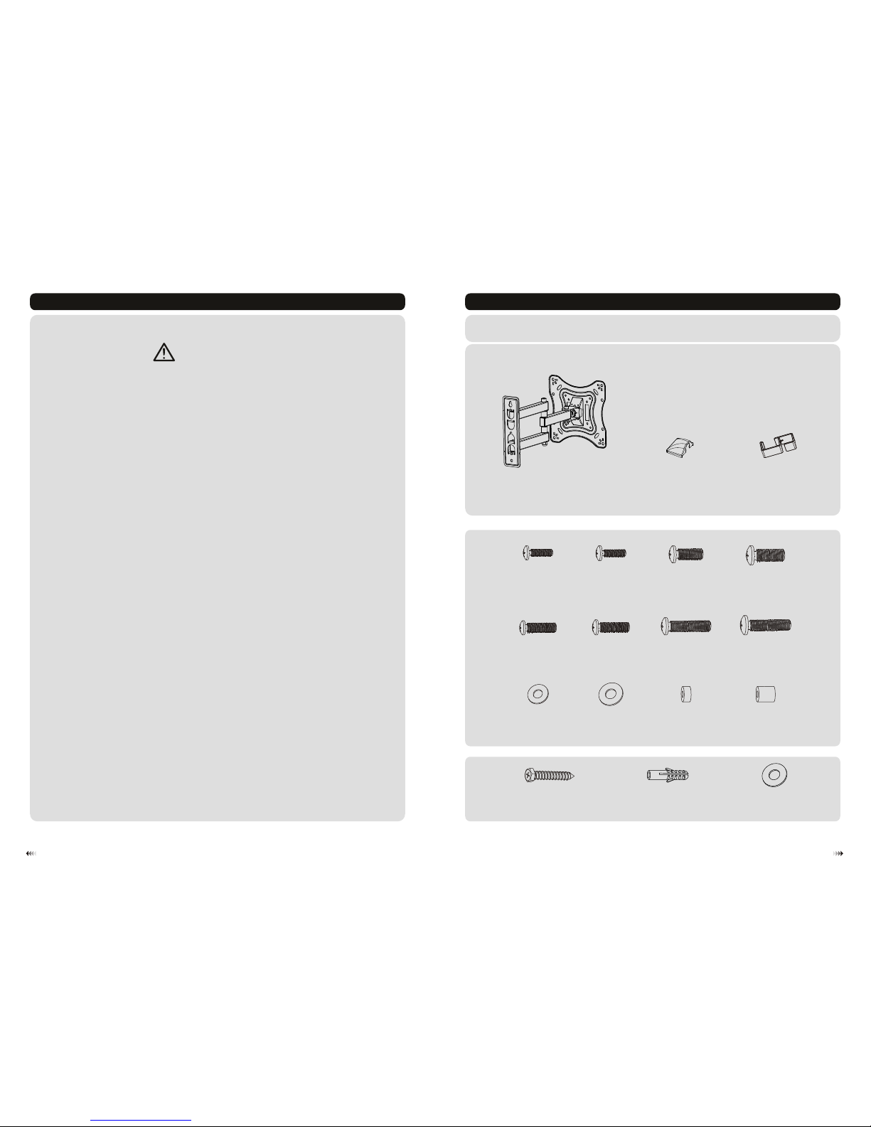
Component Checklist
WARNING
IMPOR TANT: En sure th at you ha ve rece ived al l parts a ccord ing to th e compo nent ch eckli st prio r to inst allat ion.
If an y parts a re miss ing or fa ulty, tel ephon e your lo cal dis tribu tor for a r eplac ement .
Packa ge M
Packa ge W
• Do not begin the in sta llation unti l you ha ve re ad and unde rst ood all the instructions
and wa rni ngs contained in this ins tal lat ion sheet. If you have a ny questions
regarding an y of the instructions or warnings, plea se contact you r loc al dis tri but or.
• This mounting brac ket was des ign ed to be i nst all ed and u til ise d ONLY as
specified in this ma nua l. Improper in sta lla tio n of thi s product may ca use da mag e
or ser iou s injury.
• This product sh oul d only be ins talled by s ome one with go od mechanical abi lit y
who ha s basic bui ldi ng experience and f ully unde rst and s this manu al.
• Make sure that th e supporting surf ace will sa fel y sup port the co mbi ned weigh t of
the eq uip men t and al l attached har dwa re and comp one nts .
• If mou nti ng to wo od wall stu ds, m ake sure th at mounting sc rew s are an cho red
into the center of the st uds . The us e of a stu d find er is highly rec omm end ed.
• Alway s use an a ssi sta nt or me cha nic al liftin g equ ipm ent to s afe ly lift and position
the eq uip men t.
• Tight en screws firm ly, but do not over tig hte n. Over tig hte nin g can ca use d ama ge
to the items, This grea tly r edu ces th eir h old ing power.
• This product is intended for in door use on ly. Using thi s product outd oor s could
lead to product fail ure and per son al injury.
con crete a nchor ( x3)
W-B
W-A (x 3) was her (x1 )
W-C
M-L (x4)
M4x 12
M-A
(x4 )
M4x 25
M-E
(x4 )
M5x 12
M-B
(x4 )
M5x 25
M-F
(x4 )
M6x 12
M-C
(x4 )
M6x 30
M-G
(x4 )
M8x 12
M-D
(x4 )
M8x 30
M-H
(x4 )
M-K (x4)
D8
M-J (x4)
D5
M-I(x4)
dec orati ve cove r B(x2 )
wal l mount
A
cab le dip C(x1 )
Page 3
X X
√
4
3
Inst all ers mus t veri fy tha t the sup port ing su rfac e will s afel y supp ort the c ombi ned we ight o f
the eq uipm ent an d all att ache d hard ware a nd com pone nts.
WARNING
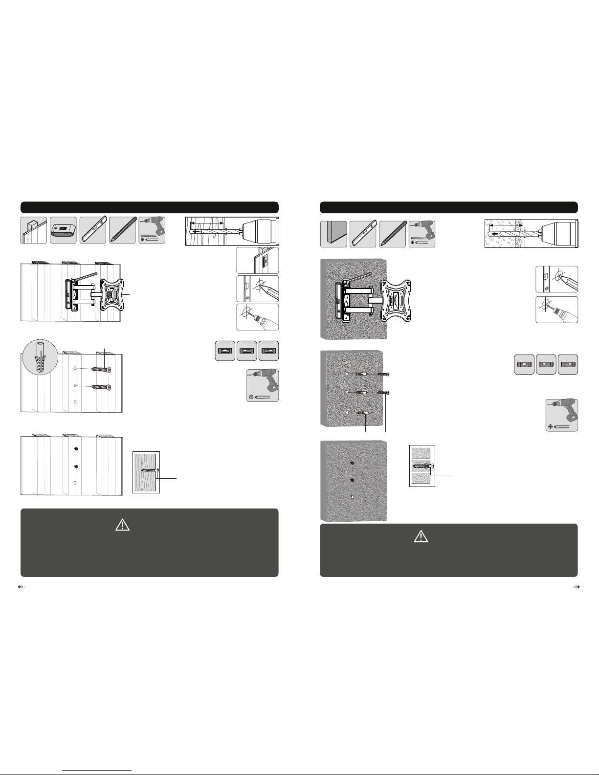
1b. For Solid Br ick and C oncrete M ounti ng
Drill pilot holes
1
2
Tighten both screws
leaving a 3mm space
from the wall.
WARNING
• Make su re that m ounti ng scre ws are an chore d into th e cente r of the st uds. Th e use of a st ud
finde r is high ly reco mmend ed.
• Insta llers m ust ver ify tha t the sup porti ng surf ace wil l safel y suppo rt the co mbine d weigh t of the
equip ment an d all att ached h ardwa re and co mpone nts.
60mm
(2.4")
60mm
(2.4")
ø 10mm
(ø 3/8")
Mark the
exact location of
mounting holes
1a. For Wood S tud Wall Mou nting
2
1
Drill pilot holes
3
Tighten both screws
leaving a 3mm space
from the wall.
X X
√
ø 4.5mm
(ø 3/16")
55mm
(2.2")
55mm
(2.2")
Find and mark the
exact location of
mounting holes
W-AW-B
3mm
3mm
W-A
X
A
Wit h the arr ows
poi nting u p
Wit h the arr ows
poi nting u p
Page 4
65
TV
TV
TV
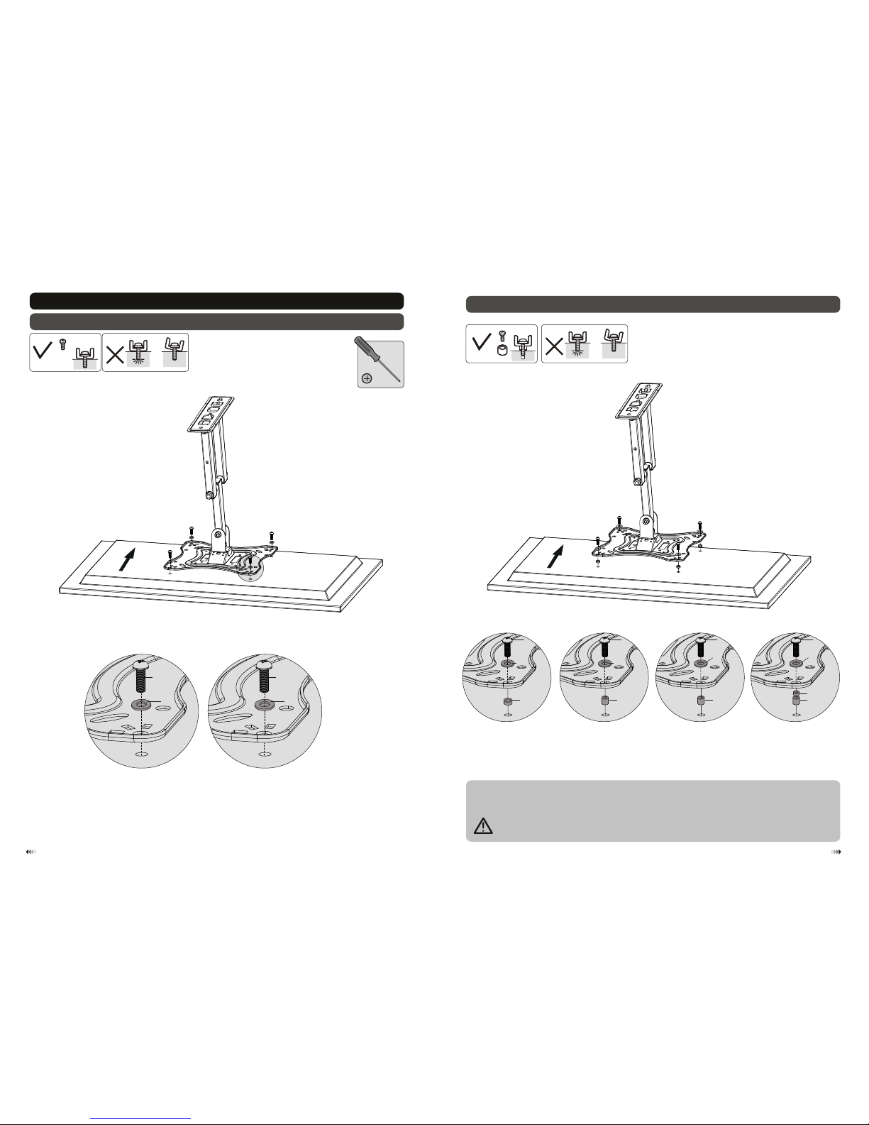
2. Installing the VESA Plate
2-1 For Fla t Back Scree ns
M-A
M-B
M-I
M-C
M-D
M-J
2-2. Fo r Recess ed Back Screen s or to Access A/V Inpu ts
Tig hten al l screw s but do no t ove r tight en.
· Scr ew the VE SA plate o nto the T V.
Note : Choose th e appropr iate scr ews an d space rs (if nece ssary) ac cordin g to t he typ e of scre en.
TV
TV
TV
M-E /M-F
M-I
M-K
M-E /M-F
M-I
M-L
M-G /M-H
M-J
M-L
M-G /M-H
M-L
M-K
M-J
Page 5
88
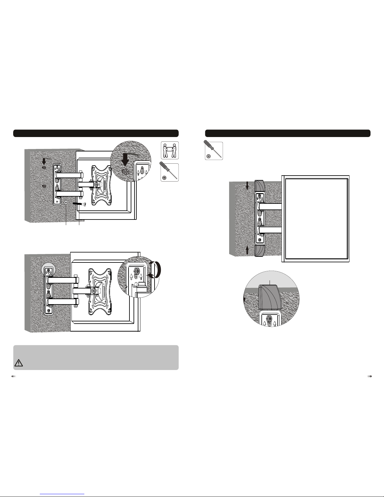
3. Installing the Wall Mount to the Wall
7
Lif t the wal l mount ( attac hed the T V),Al ign the h oles in t he wall p late wi th the sc rew hea ds on the w all and
low er the wa ll plat e. Then i nstal l the rem ainin g screw t hroug h the was her.
W-AW -C
4. Installing the Decorative Covers
B
Tig hten al l screw s but do no t ove r tight en.
Page 6
10
9
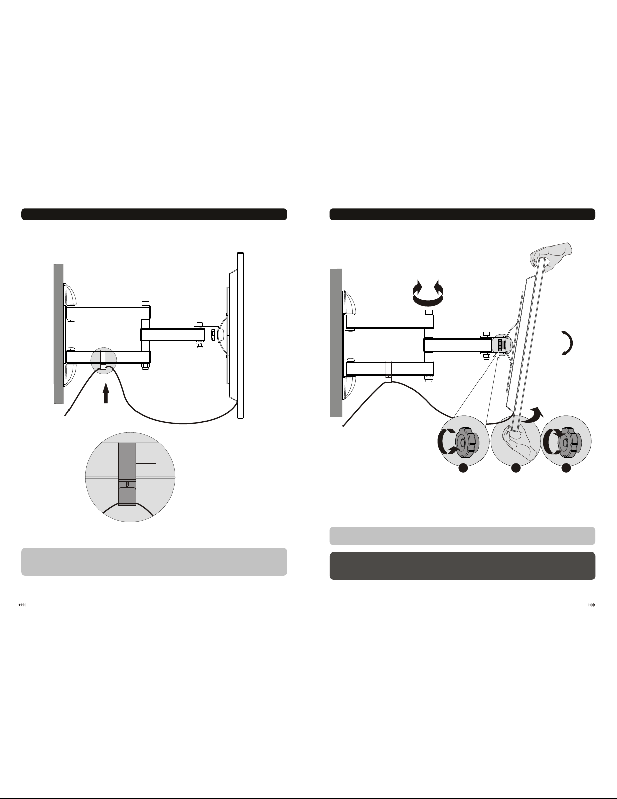
6. Adjustment
5. Cable Management
• Ins tall th e cable c lip.
• Con nect th e cable s to your T V and rou te the ca bles th rough t he cabl e clip.
Note: Leave slack in the cables for cantilever arm movement.
C
• Adju st to the d esire d posit ion or ti lt.
Mai ntena nce
• Che ck that t he brac ket is se cure an d safe to u se at reg ular in terva ls(at l east ev ery thr ee mont hs).
• Ple ase con tact yo ur dist ribut or if you h ave any q uesti ons.
• Loo sen the k nob to ad just th e TV to the d esire d angle t hen tig hten th e knob to s ecure .
1
8
0
°
+20°
-20°
2 31
 Loading...