


RZ2 BioAmp Processor
Operator’s Manual

RZ2 BioAmp Processor Operator’s Manual
Copyright
© 2008-2013 Tucker-Davis Technologies, Inc. (TDT). All rights reserved.
No part of this manual may be reproduced or transmitted in any form or by any means,
electronic or mechanical, including photocopying and recording, for any purpose without
the express written permission of TDT.
Tucker-Davis Technologies
11930 Research Circle
Alachua, FL 32615
USA
Phone: 386.462.9622
Fax: 386.462.5365
Notices
The information contained in this document is provided “as is,” and is subject to being
changed, without notice. TDT shall not be liable for errors or damages in connection with
the furnishing, use, or performance of this document or of any information contained
herein.
The latest versions of TDT documents are always online at www.tdt.com/support.htm.
A CAUTION informs users when failure to take or avoid a specified action could result
in damage to the product or loss of data.
A WARNING calls attention to an operating procedure or practice that, if not correctly
performed or adhered to, could result in personal injury or death. Do not proceed beyond
a WARNING notice until the indicated conditions are fully understood and met.
Updated: 1/17/2019 11:37 AM

1
Operator’s Manual
RZ2 High Performance Processor
The RZ2 High Performance Processor is the first in TDT’s Z-Series line of ultra high performance
processors and has been designed for high channel count neurophysiological recording and signal
processing. The RZ2 offers the ultimate in performance by building on the strengths of its
predecessors while improving flexibility and overall processing power.
Functional Diagram
The RZ2 device chassis houses an integrated zBUS communication interface and power source.
Power Supply
The RZ2’s power supply is integrated into the device and is shipped from the factory with the
desired voltage setting (115 V or 230V) preset. If you need to change the voltage settings for
different regional use please contact TDT support at 1-386-462-9622 or email support@tdt.com.

2
Using the RZ2 Processor Device
This manual provides the directions necessary for powering the RZ2 High Performance Processor
on and off as well as its communications functionality and User Interface features. Refer to the
System 3 Manual provided by TDT for specific instructions on how to program the RZ2 Processor
device.
Applying Power to the RZ2
CAUTION! Allow at least 2 cm clearance from each side of the RZ2 chassis for proper
cooling. A ventilation fan is provided on the each side of the RZ2 chassis.
Installation of the RZ2 chassis with the ventilation obstructed may cause a
malfunction or fire.
Use only the supplied power cord.
To turn the RZ2 on:
1. Position the RZ2 chassis so that both the power switch and power cord may be accessed
easily.
2. Ensure that the power switch is off and connect the power cord.
3. Turn the power switch on and check that the power switch's blue LED is illuminated.
Disconnecting Power from the RZ2
CAUTION! When removing the power cord from either the power supply or socket
outlet, grasp the plug, not the cord, in order to avoid damaging the cable.
To disconnect the RZ2:
1. Turn off the power switch.
2. Disconnect the power cord from the power supply.
3. Disconnect the power cord from the wall socket plug.
The RZ2 Communications Interface
The RZ2's Optibit optical interface is integrated into the device and connectors are provided on the
back panel. The connectors on the fiber optic pair used for PC communication are color coded for
correct wiring.
CAUTION! The fiber-optic cables have raised keys on one side of the connector. There
are also keyway notches on the inside of the connector on the RZ2
communications interface module; to avoid damage to the interface and
cables, the fiber-optic cable should be oriented so that the keys on the cable
connectors line up with the keyway notches on the module.

RZ2 BioAmp Processor Operator’s Manual
3
Optional UDP Interface
The RZ UDP Ethernet interface is designed to transfer data to or from a PC. The RZ UDP
interface (if available) is located on the back panel of the RZ processor and accepts a standard
Ethernet cable. Refer to the UDP User Guide for more information.
The Indicator Light
A front panel switch turns on the RZ2 power supply and includes an indicator light. The power
switch's blue LED will illuminate when the chassis is switched on.
RZ2 Display LCD
CAUTION! To avoid potential damage, do not place any sharp objects near the RZ2
Display LCD.
The LCD display shows information about each DSP, the optical PC interface, the PZ preamplifier
and system I/O. A selection knob allows the user to highlight a section of the screen to display
more detailed information. Rotate the selection knob to select a system component. Once the
selection has been made, push the knob and expand the information view. Refer to the RZ2 User
Guide in the System 3 Manual for more information.
RZ2 Input and Output Ports
CAUTION! The input and output ports located on the front panel of the RZ2 chassis
contain sensitive electronics. Refer to the RZ2 Technical Specifications in
the System 3 Manual before making any connections.
The RZ2 is equipped with several different analog and digital I/O capabilities. The high speed and
legacy fiber optic ports allow a direct connection to Z-Series or Medusa Preamplifiers. The RZ2
also includes onboard D/A and A/D conversion for stimulus generation, experiment control, and
input of signals from a variety of other analog sources. Digital and analog source channels may be
accessed via standard 25-pin I/O connectors labeled Digital I/O and Analog I/O. Additionally,
digital source channels can be accessed through front panel BNCs marked Port A and Port C,
while analog source channels can be accessed through Port D and Port E respectively. Refer to the
RZ2 User Guide in the System 3 Manual for more information.
Connecting the RZ2 Interface to your PC
Before connections can be made from the RZ2 to your PC, the PCI interface card must be installed
inside your PC. For more information refer to Installing the Optibit Interface in the System 3
Installation Guide.
After the necessary connections have been made to your PC connections from the RZ2 to the
Optibit interface card are shown in the following diagram.

4
Connecting the RZ2 Interface to a PZ Preamplifier
When connecting the RZ2 to any PZ Preamplifier, ensure that the wires are inserted correctly. The
RED label on the back of the RZ2 denotes the input for the red colored fiber optic wire. Similarly,
another label titled RED is shown on the back of the PZ Preamplifier.

RZ2 BioAmp Processor Operator’s Manual
5
Maintaining the RZ2
Safety Notices
This device has passed rigorous testing by Underwriters Laboratories and is UL compliant for
CAT II installation in laboratories and other indoor environments. Before applying power to the
RZ2 chassis, verify that the correct safety precautions are taken.
WARNINGS! Read the following warnings prior to operation.
➢ If the device is damaged, or fails to operate according to the specifications described in
this manual, disconnect the power cord and contact TDT support immediately.
➢ The mains disconnect for the device is the power cord. To completely disconnect power
to the device, the power cord must be disconnected.
➢ The power cord is to be readily accessible after installation and during operation.
➢ Before applying power to the device, you must correctly connect the power cord to a
properly rated standard socket outlet provided with a protective earth contact.
➢ In the event of impaired ground protection, avoid using the device to prevent possible
damage.
➢ When removing the power cord from either the power supply or socket outlet, grasp the
plug, not the cord, in order to avoid damaging the cable.
➢ Do not attempt to disassemble the power supply or chassis by removing any of the
exterior housing of the RZ2. If you experience any issues, contact TDT support
immediately.
➢ Do not attempt to alter this device in any way that deviates from its intended operation as
described in this operator’s manual.
➢ Capacitors contained inside the device may retain their charge even after power has been
disconnected from its supply source.
➢ Operation of this device in the presence of flammable gases or fumes is strictly prohibited
to avoid definite safety hazards.
➢ Do not subject this device to excessive vibration or shocks during handling or shipping,
and avoid dropping the device.
➢ Although there is a protective screen over the ventilation fan, do not attempt to stick any
objects into the fan. This may result in injury or damage to the device.
➢ Do not attempt to store this device where it may be exposed to prolonged periods of
excessive sunlight, high temperatures, high humidity, or condensation. If exposed to such
conditions, the device may no longer work properly and its specifications may no longer
be satisfied.
➢ The device is for indoor use only and is not waterproof; do not get the device wet.
➢ Do not attempt to use this device in a manner unspecified by TDT.
6
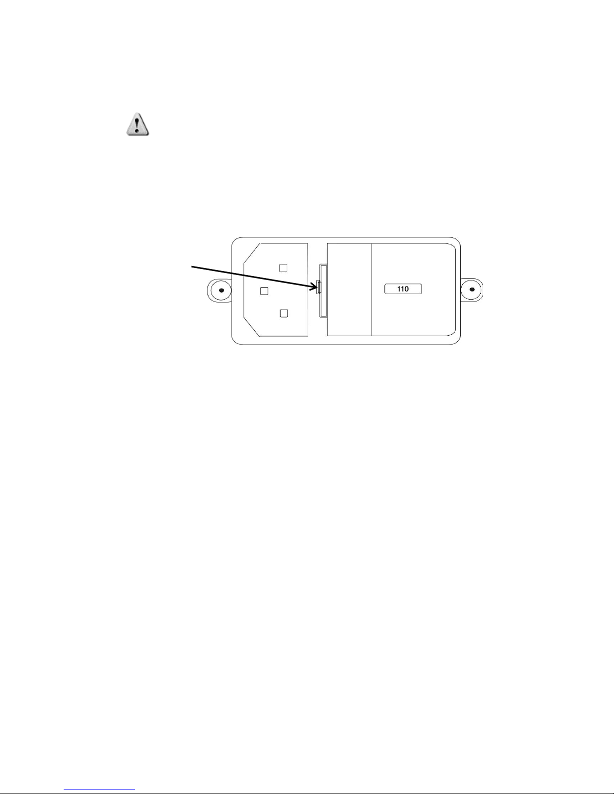
Changing the Power Supply Fuses
CAUTION! Only fuses with the required rated current, voltage, and specified type should
be used with this device. Use only 5 x 20mm, 250V 1.6A rated, slow-blow fuses.
To change the power supply fuses:
1. Turn off the power switch. Disconnect the power cord from the power supply.
2. Using a small flathead screwdriver gently push the clip along the left side of the fuse
plate to the right.
3. When the fuse plate pops free, gently slide the fuse plate and housing out of the power
supply.
4. The housing contains two fuses. Replace the defective/broken fuse(s) with a new 5 x
20mm, 250V 1.6A rated, slow-blow fuse by gently pushing the end of the fuse into the
fuse housing.
5. Push the fuse housing back into the power supply and press gently until the clip clicks
into place.
Cleaning the RZ2 Processor Device
To clean the device:
1. Remove power from the RZ2 device chassis.
2. Clean the external surfaces and LCD screen of the device with a soft, dry cloth.
3. Do not attempt to disassemble and clean the inside of the device.
Push Fuse
Clip to the
right.

RZ2 BioAmp Processor Operator’s Manual
7
RZ2 Technical Specifications
Technical specifications for the RZ2 Processor Device. Refer to the RZ2 Technical Specifications
in the System 3 Manual for more information.
Chassis
Height
3U
Width
Standard 19’’ rack mount
Power Supply (Integrated)
Maximum Working Voltage
HI to earth ground 230V max
LO to earth ground 230V max
Main Voltage Rating
115/230 V, 50/60 Hz, 40 VA AC
Installation Category
CAT II
Environmental
Operating Temperature
0 to 40°C
Storage Temperature
5 to 40°C
Humidity
80% for temperatures up to 31°C, decreasing
linearly to 50% RH at 40°C
Maximum Altitude
2,000 m
Pollution Degree
2 (Indoor use only)
 Loading...