

Tucker Auto-Mation THE BAT Installation Manual
!
!
!
920.1004.02!
1!!!!!!!!!!!!!!!!!!!!!!!!!!!!!!!!!!!!!!!!!!!
!
!
!
!
!
!
!
!
THE BAT
MOTION SENSOR

!
!
!
920.1004.02!
2!!!!!!!!!!!!!!!!!!!!!!!!!!!!!!!!!!!!!!!!!!!
IMPORTANT
READ THIS SECTION BEFORE PROCEEDING WITH INSTALLATION
INSTALLATION PRECAUTIONS
Tucker Auto-Mation, LLC (hereafter referred to as “Tucker”) recommends that all of its automated pedestrian door
products be installed by a trained automatic door technician and that the resulting performance of the product be in
full compliance with the most current version of the American National Standards Institute document A156.10 or
A156.19 (whichever is applicable) as well as any applicable building codes and/or fire codes. Tucker further
recommends that a full inspection of the operating system be performed in accordance with the guidelines of the
American Association of Automatic Door manufacturers (AAADM). This inspection must be performed by a
certified AAADM trained inspector. Tucker recommends this documented inspection be performed upon
completion of the installation as well as, following the completion of every service call thereafter. If service is not
performed within one year of the previous service action, a routine AAADM inspection should be performed and
documented. Under no circumstance should the product operate for more than one year without an AAADM
inspection. Tucker does NOT recommend installation or service, on any of their automated pedestrian door products,
by any individual who is not certified as an AAADM inspector. Following the installation or service of any Tucker
automated pedestrian door product, if it is deemed unsafe, or is operating in an unsatisfactory manner according to
national performance standards or recommended performance guidelines as defined by Tucker, repairs should be
made immediately. If an immediate repair cannot be made, the product should be disables, and appropriate
measures should be taken to secure the door in a safe position or to enable the door to safely be used manually.
During this situation, every effort should be made to notify the owner (or person responsible) of the condition and to
advise on corrective actions that must be taken to return the product to safe operation.

!
!
!
920.1004.02!
3!!!!!!!!!!!!!!!!!!!!!!!!!!!!!!!!!!!!!!!!!!!
DESCRIPTION & SPECIFICATION
THE BAT Sensor is a motion sensor operating at 24 GHz K-Band microwave technology. It is used for primary or
secondary activation on automatic pedestrian doors. It may be used for swinging, sliding, folding, and revolving
doors.
!
DESCRIPTION
SPECIFICATION
Product Part Number
200.1068
Document Number
920.1004.02
Microwave Frequency
24.15…24.25 GHZ
Transmitting Power
<20 dbm
Power Consumption
<50mA
Output Relay
Dry contact normally open (N.O.) or normally closed (N.C.)
Operating Voltage
12…36VDC 12…28VAC
Max. Contact Switching Voltage
48 Volts AC / DC
Max. Contact Switching Current
Max. 0.5A AC / 1A DC (resistive)
Relay Hold Time
Factory setting: 1 Second (Adjustable 0.2 Seconds to 5 Seconds).
Detection Speed
Standard 4” per Second (10 cm, per Second)
Angle
Vertical 0° to +90°
Horizontal -30° to +30°
Mounting Height
7’ (2.1m) standard
13’ (4m) maximum
Degree of Protection
NEMA 3S (IP54)
Temperature Range
-4°F to +131°F (-20°C to +55°C)
Dimensions
4.8” (W) x 2.6” (H) x 2.3” (D) (123mm x 64mm x 58mm)
Weight
4.6 ounces (130g)
Conformity
US: Compliant with FCC regulations, part 15.
Canada: Contains IC approved component.
Material
Polycarbonate (PC), ABS
Housing Color
Black
Cable Length
6ft (2m)
!
!
!
!
920.1004.02!
4!!!!!!!!!!!!!!!!!!!!!!!!!!!!!!!!!!!!!!!!!!!
INSTALLATION INFORMATION
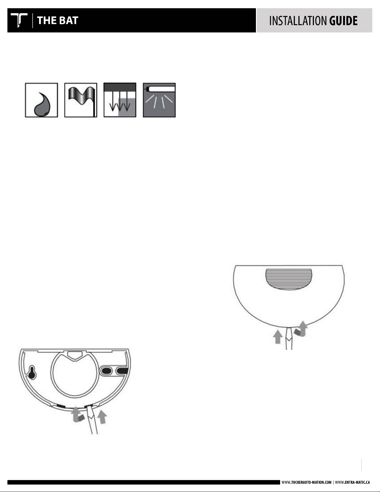
• Protect the sensor from rain
• Avoid moving objects in the detection are (fans,
plants, trees, flags).
• Do not obstruct the sensor and mount it only
behind suitable covers. Mechanically-operated
drive components can affect the sensor.
• Avoid fluorescent lights in the detection area.
REMOVE COVER
1. Insert screwdriver in slot at bottom of sensor and slightly pry down.
2. Pull cover away from the base.
!
!
!
920.1004.02!
5!!!!!!!!!!!!!!!!!!!!!!!!!!!!!!!!!!!!!!!!!!!
MECHANICAL INSTALLATION
The BAT sensor is not limited to a specific mount location. It has the capability to
be mounted at an angle and its microwave antenna may also be tilted up or down
to various angles. The most common location is on the center of the automatic
door header.
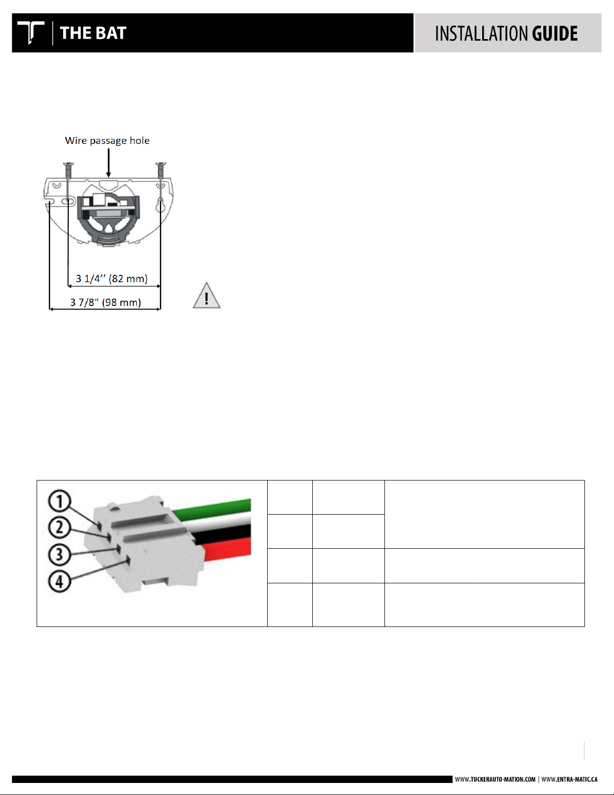
1. Apply the mount template at the desired location.
2. Drill pilot holes for the screw mounts and drill a clearance hole for the wire
passage as instructed.
3. Attach sensor backing with the self-tapping screws.
4. Route the wire through the passage hole to the desired location.
Additional bracket (optional) required for ceiling mount.
The max. mounting height is 13’ (4m).
WIRE THE SENSOR
The BAT sensor provides a dry relay output and may be connected directly to the activation circuit
of the automatic door control.
ü TERMINAL BLOCK
PIN 1
Red (+)
Power 12 to 28 VAC
Or
12 to 36 VDC
PIN 2
Black (-)
PIN 3
White
Relay Common
PIN 4
Green
Relay N.O. (Dip Switch #5 OFF N.C. #6 ON)
Relay N.C. (Dip Switch #5 OFF #6 OFF)
 Loading...