

Tucker Auto-Mation SW10, SW19 Installation Manual

!
!
!
920.1020.12 !
1!!!!!!!!!!!!!!!!!!!!!!!!!!!!!!!!!!!!!!!!!!!
!
!
!
!
!
!
!
!
!
!
TUCKER AUTO-MATION
SW10 (Full Power) & SW19 (Low Energy)
INSTALLATION GUIDE
Surface Mounted Applications
(See APPENDIX for special notes regarding installation on fire rated doors)
!
PLEASE NOTE: NEW 35mm SPINDLE FOR PUSH APPLICATIONS REQUIRES DIFFERENT
HEADER MOUNTING HEIGHT

!
!
!
920.1020.12 !
2!!!!!!!!!!!!!!!!!!!!!!!!!!!!!!!!!!!!!!!!!!!
IMPORTANT
READ THIS SECTION BEFORE PROCEEDING WITH INSTALLATION
Tucker Auto-Mation, LLC (hereafter referred to as “Tucker”) recommends that all of its
automated pedestrian door products beinstalled by a trained automatic door technician and that the
resulting performance of the product be in full compliance with themost current version of the American
National Standards Institute document A156.10 or A156.19 (whichever is applicable) as well as any
applicable building codes and/or fire codes. Tucker further recommends that a full inspection of the
operating system be performed in accordance with the guidelines of the American Association of Automatic
Door manufacturers (AAADM). This inspection must be performed by a certified AAADM trained inspector.
Tucker recommends this documented inspection be performed upon completion of the installation as well
as, following the completion of every service call thereafter. If service is not performed within one year of
the previous service action, a routine AAADM inspection should be performed and documented. Under no
circumstance should the product operate for more than one year without an AAADM inspection. Tucker
does NOT recommend installation or service, on any of their automated pedestrian door products, by any
individual who is not certified as an AAADM inspector.
Following the installation or service of any Tucker automated pedestrian door product, if it is deemed
unsafe, or is operating in an unsatisfactory manner according to national performance standards or
recommended performance guidelines as defined by Tucker, repairs should be made immediately. If an
immediate repair cannot be made, the product should be disabled, and appropriate measures should be
taken to secure the door in a safe position or to enable the door to safely be used manually. During this
situation, every effort should be made to notify the owner (or person responsible) of the condition and to
advise on corrective actions that must be taken to return the product to safe operation.
LOW ENERGY APPLICATION NOTE
When using the SW10/19 for a low energy application, Tucker Auto-Mation recommends the use of a doormounted presence sensor on the approach side of the door to be used as a secondary activation device. This
type of sensor can be installed at time of installation or can also be retrofitted. This device serves to reactivate the door to the open position should a person enter into the closing path at the approach side of
the door, as it is closing. Once the door is fully closed, a "knowing act" device must then be used for initial
activation. Tucker Auto-Mation considers this device to be essential in reducing the possibility of doors
"timing out" and closing before all pedestrians have passed though the doorway. Check with your Tucker
sales representative to find out about special incentives that may be available for the Torpedo 1 doormounted presence sensor.

!
!
!
920.1020.12 !
3!!!!!!!!!!!!!!!!!!!!!!!!!!!!!!!!!!!!!!!!!!!
!
TABLE OF CONTENTS:
!
!
Page
Contents
IMPORTANT
READ IMPORTANT NOTICE ABOVE BEFORE BEGINNING TH
E
I
NSTALLATION
OF THIS PRODUCT
2
Important Notices
4
Product
Description & Specifications
5
STEP
1: Header Installation
6-7
STEP
2: Mounting The
Operator & Control Assembly
8-9
STEP
3: Install The Arm Assembly - Standard Applications
10-14
STEP
4: OPTIONAL
- Push
Arm Installation With Increased
Spring Tension
15
STEP
5: OPTIONAL
-
Pull Arm Installation With Increased
Spring Tension
16-17
STEP
6: Adjusting The Mechanical Stops
18-20
STEP
7: Setting The Dip Switches
21
STEP
8:
Wiring Connections
22
STEP
9: Adjusting The Control
23
STEP
10: 120 Volt
AC C
onnection
24-27
STEP
11: Power On & Tune-In
28
T
roubleshooting 28
Job Documentation & Closeout
29
Company Contact
30-31
Appendix - Adjusting The Chain Tensioner
31-38
Appendix –
Wiring Diagrams
39
Appendix - Lock Relay Function
40-41
Appendix -
Fire
rated Door Application
42
Appendix - Tucker Logo Placement
!
!

!
!
!
920.1020.12 !
4!!!!!!!!!!!!!!!!!!!!!!!!!!!!!!!!!!!!!!!!!!!
PRODUCT DESCRIPTION & SPECIFICATIONS
The Tucker Auto-Mation SW10 & drives. The unique design offers; non-including sensors, push plates, fire
alarm, and electric locks. Troubleshooting when needed. Both units can be configured concealed
application. The Tucker Advanced Programmer (TAP) is provided as an option to access additional
programming features.
!
!
Power Supply
115
VAC (+6%, -10%)
60Hz
Power Consumption
100W
C
urrent Consumption
1A Motor
24
VDC
Permanent Magnet
With Belt Driven Encoder
Header Dimensions
20 3/4” x 4 1/8” x 4 3/4”
(l
x w x d)
Fused Protection
3.5A Fuse (F1 located on I/O Board)
Weight
22
lbs
Per Operator Assembly
Ambient Operating Temperature
-4 to 131º F
Ingress Protection
IP23 (protection
from spray water up to 60º from
the
vertical – ie. Rainstorm)
Maximum
Door Weight
PUSH ARM
PULL ARM
36” Door: 438
lbs
342 lbs
42” Door: 328
lbs
256 lbs
44” Door: 299
lbs
234 lbs
48” Door: 254
lbs
198 lbs
24
VDC Accessories
Power Supply
24
VDC / 500
mA
max.
24
VDC Electric Lock Power Supply
24
VDC / 500
mA
max.
Adjustable Speeds & Timers
Opening Speed
Closing Speed
Hold
Open Time
Standard Selector Switch Functions
Automatic
Hold
Ope
n
Manual
(Off)
Standard Control Outputs
Malfunction Alarm Signal
Electric Lock
Power Supply
24
VDC Accessories
Power Supply
Door
Status
Standard Control Inputs
Interior Activation
Exterior Activation
Emergency
Shutdown Alarm
Output
“Stop” Safety Device (door-m
ounted)
Quick Disc
onnects
TAP-Controller (optional)
!
!
!
!
!
!
!
!
920.1020.12 !
5!!!!!!!!!!!!!!!!!!!!!!!!!!!!!!!!!!!!!!!!!!!
!
!
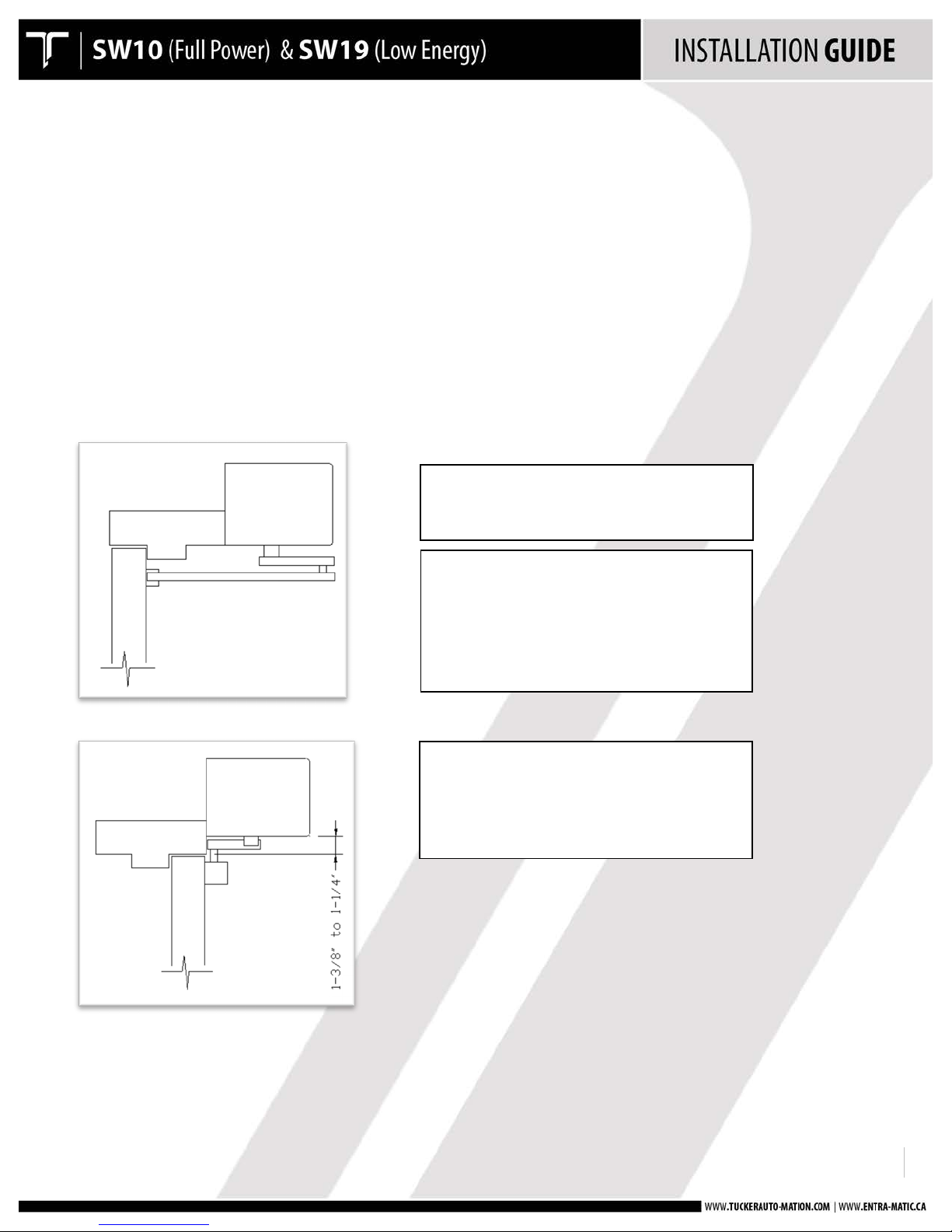
STEP 1: HEADER INSTALLATION
Mount the back-plate to the top door frame using appropriate fasteners for the type of frame.
• Push side mounting: Back-plate is flush with bottom of door frame.
• Pull side mounting: Back-Plate is mounted 1.5” up from bottom door frame.
• Back-plate should overlap each jamb tube by 1.5” – to aide in installation, there is an index line
scribed into the back-plate at 1.5” in from the edge. Align this mark with the inside face of the jamb
tube.
• Refer to the APPENDIX for fire rated door applications.
!
!
!
!
!
!
!
!
!
!
!
!
!
!
!
!
!
!
!
!
!
!
PUSH!ARM!APPLICATIONS:!!
Bottom!of!header!is!flush!with!bottom!of!top!
frame.!
PULL!ARM!APPLICATION:!STANDARD!PULL!
ARM!&!DOUBLE!EGRESS!APPLICATIONS!
Double!egress!applications!require!the!use!of!
an!80mm!spindle!adaptor!for!the!side!using!
the!push!arm.!
NOTE:!
Tucker!Auto-Mation!is!now!using!a!35mm!
spindle!adaptor!for!all!standard!push!arm!
applications!–!this!requires!that!the!header!
assembly!be!mounted!as!shown!at!left,!flush!
with!bottom!of!top!frame.!
!
!
!
920.1020.12 !
6!!!!!!!!!!!!!!!!!!!!!!!!!!!!!!!!!!!!!!!!!!!
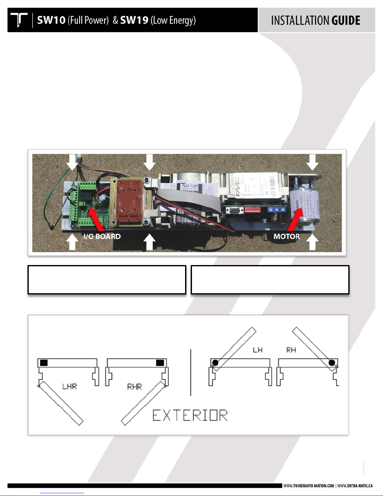
STEP 2: MOUNT THE OPERATOR(S)
• One operator works for any hand of door.
• The hand depends on how the operator is mounted to the header.
• Refer to the APPENDIX for fire-rated door applications.
• Determine the hand of the door to be automated and mount the operator & short back-plate
assembly using the 6 screws provided.
!
!
!
!
!
I/O BOARD IS TOWARDS HINGE
JAMB
MOTOR TOWARDS HINGE JAMB
!
!
!
920.1020.12 !
7!!!!!!!!!!!!!!!!!!!!!!!!!!!!!!!!!!!!!!!!!!!
!
!
!
!
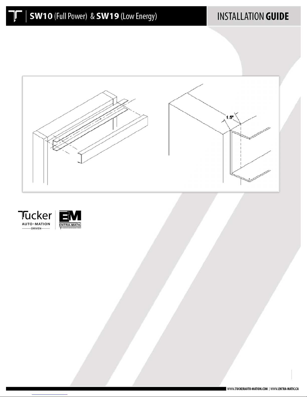
• Mount the header to the doorframe with the screws provided.
• The header will overlap the doorframe by 1-1/2" at each side.!
!
!
!
!
!
!
!
!
!
!
!
!
!
!
!
!
!
!
!
!
!
!
!
!
!
920.1020.12 !
8!!!!!!!!!!!!!!!!!!!!!!!!!!!!!!!!!!!!!!!!!!!
!
!
!
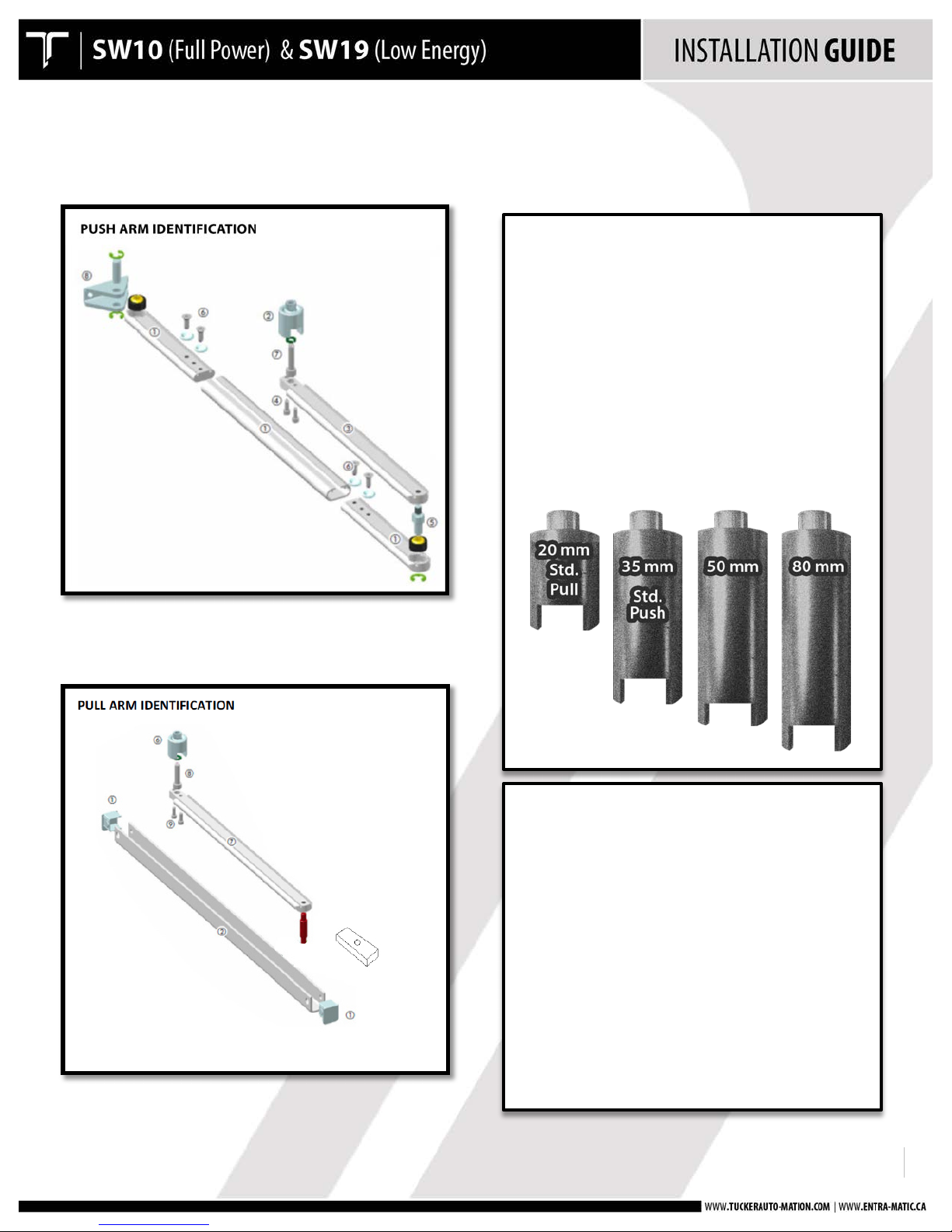
STEP
3:
INSTALL THE ARM ASSEMBLY - STANDARD APPLICATIO
N
!
!
!
!
!
PUSH ARM ASSEMBLY:
1. Secondary Arm With Sleeve
2. Spindle Adaptor
3. Primary Arm
4. Spindle/Arm Attachment Screw
5. Pivot Stud
6. Secondary Arm Attachment
Screws With Dimple Washers
7. Spindle Adaptor Bolt
8. Door Shoe
PULL ARM ASSEMBLY:
1. End caps
2. Slide Track
3. Slide Block Sub-Assembly
4. Slide Blocks
5. Slide Block Separator
6. Slide Block Stud
7. Primary Arm
8. Spindle adaptor Bolt
9. Spindle Adaptor/Arm Attachment
!
!
!
920.1020.12 !
9!!!!!!!!!!!!!!!!!!!!!!!!!!!!!!!!!!!!!!!!!!!
STEP
3:
INSTALL THE ARM ASSEMBLY - STANDARD APPLICATION
Follow
the instructions listed below
for a standard arm application using
a "push" or a
"pull"
arm assembly.
If using a push arm,
AND
extra door
closing
force
is require,
follow
the instructions
on page 7 for "Optional
-
Push
Arm Installation
With Increased
Spring Tension"
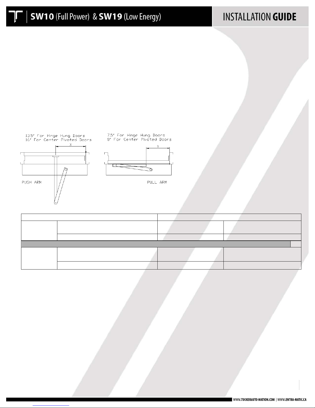
PUSH ARM APPLICATIO
N
Ensure
the main
power
supply is
removed or shut off at the control.
HINGE HUNG
DOORS
CENTER PIVOTED
DOORS
PUSH
APPLICATIO
N
C/L
of
Hinge
to C/L of
Arm Mount
Bracket
Inside face of pivo
t
jamb to Spindle
Inside face of hinge jamb to
C/L
of
Arm
Mount Bracke
t
13.5”
10.5”
16”
PULL
A
PPLI
CATIO
N
Inside face of jamb to
Back Edge
of
Slide Trac
k
Inside face of pivo
t
jamb to Spindle
Inside face of hinge jamb to
Back Edge
of
Slide Trac
k
7 .5 ”
10.5”
8”
!
PULL ARM APPLICATION:
• Includes double egress applications.
• Ensure the main power supply is removed or shut off at the control.
• Install the slide track assembly to the door at the specified location.
• Attach the track with the screws provided.
• Install the primary door arm and spindle onto the operator so that the arm is approximately 30 to 45
degrees past the door closed position.
• Once the arm is installed and tightened, pull the arm towards the opening direction and insert the
drive block into the track assembly.
!
!
!
920.1020.12 !
10!!!!!!!!!!!!!!!!!!!!!!!!!!!!!!!!!!!!!!!!!!!
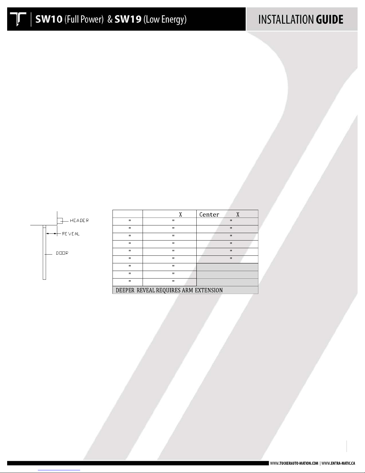
Reveal!
Hinge!Hung! Dim.!
!Pivot! Dim.!
0 !
13 !
16 !
1 !
14 !
17 !
2 !
15 !
18 !
3 !
16 !
19 !
4 !
17 !
20 !
5 !
18 !
21 !
6 !
19 !
!
7 !
20 !
!
8 !
21 !
!
!
!
• Manually move the door from the full closed position to the full open position to make sure there is
enough travel from the operator.
• If more travel is required, adjustment of the mechanical stops on the operator may be required.
• See the next section for adjustment if needed.
STEP
4: OPTIONAL
-
PUSH ARM INSTALLATION WITH INCREASED SPRING
TENSION
!
• Prior to beginning the push arm installation, gather the following information about the application:
o Door configuration
o Reveal distance (inches)
• Use the chart below to determine the prescribed length of the secondary arm assembly and note the
dimensions.
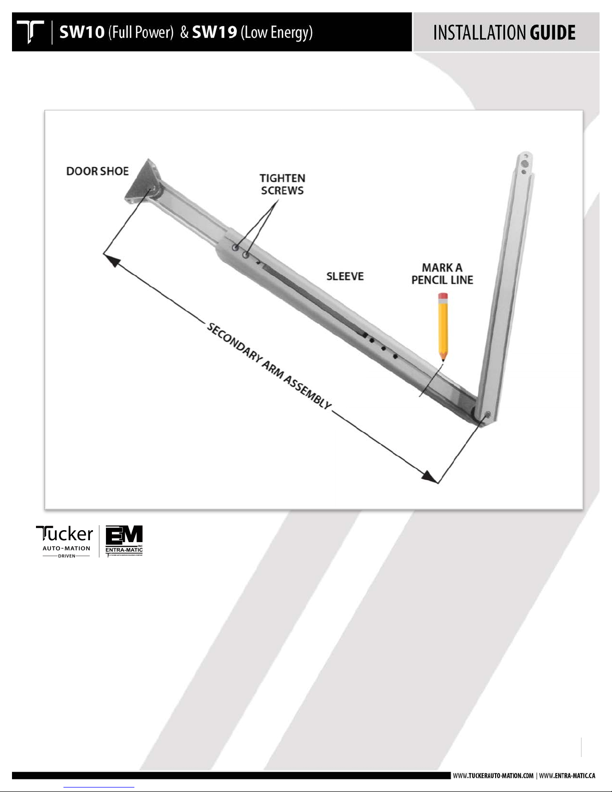
• Before
installing
any
portion of the door arm assembly, it
is easiest to
lay
the arm out on a flat
surface and insert
the secondary and primary
arm into
the sleeve as it will
be when installed
on
the
door:
o
Slide
the short arms within
the sleeve to obtain the prescribed
"X" dimension.
o Tighten the screws on the short arm that
is
connected to the door shoe.
o
Double-check
the
"X" dimension
of the arm - this is
the distance
between the center of the
hole
at the
door
shoe and the center of the hole at the pivot point
of the primary
arm (as
shown).
o Mark a
pencil line
at the edge of the sleeve where it overlaps the short arm that
is
connected
to the primary
arm.
This will
make it easier when positioning the primary
arm for
final
installation.
!
!
!
920.1020.12 !
11!!!!!!!!!!!!!!!!!!!!!!!!!!!!!!!!!!!!!!!!!!!
PUSH ARM
!
!
!
920.1020.12 !
12!!!!!!!!!!!!!!!!!!!!!!!!!!!!!!!!!!!!!!!!!!!
STEP 4 Cont.: OPTIONAL - PUSH ARM INSTALLATION WITH
INCREASED SPRING TENSION
!
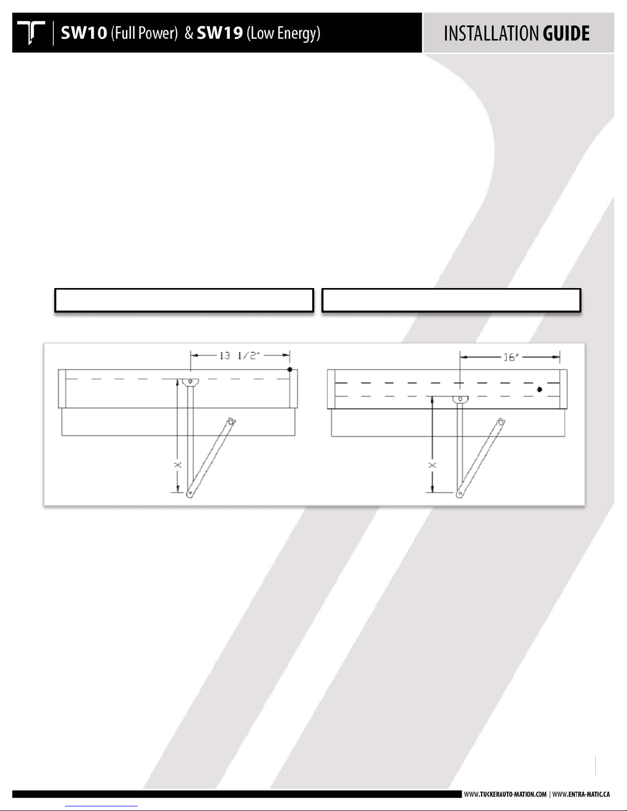
• The door shoe and short arm comes pre-assembled - it is
not necessary to take the assembly apart.
• Install
the door shoe per the door hinge / pivot configuration - see below:
o
Hinge Hung Doors: Centerline of door shoe at 13.5"
in
from inside
of hinge jamb
o Center Pivot Doors: Centerline of door shoe at 16"
in
from inside
of pivot jamb
o The
horizontal centerline
of the door shoe
will
be at 2" below the bottom of the back-plate
o
Do NOT
install
the primary
arm until instructed to do so
HINGE HUNG
CENTER PIVOTED

!
!
!
920.1020.12 !
13!!!!!!!!!!!!!!!!!!!!!!!!!!!!!!!!!!!!!!!!!!!
• Ensure the mechanical door stops are at their maximum position as shown.
• Apply 120 VAC Main power to the control
o Place the On-Off-Hold switch to the Hold Open position
 Loading...