

Page 1

920.1037.02
Page 2

CONTENT
IMPORTANT SAFETY INSTRUCTIONS WARNING _________________________________________________________03
ZAP CONTROL SYSTEM _________________________________________________________________________ 04
OPERATOR PACKAGE __________________________________________________________________________05
DIMENSIONS _______________________________________________________________________________06
OPERATOR INSTALLATION _______________________________________________________________________07
STEP 01 - BEFORE INSTALLING THE OPERATOR ___________________________________________________________08
STEP 02 - OPERATOR MOUNTING ___________________________________________________________________09
STEP 03 - GENERAL INSTALLATION __________________________________________________________________10
STEP 04 - FITTING THE MANUAL OVERRIDE LEVER MECHANISM _________________________________________________12
STEP 05 - FITTING THE WALL BUTTON ________________________________________________________________14
STEP 06 - WALL BUTTON - CONNECTION _______________________________________________________________14
STEP 07 - TRANSMITTER KEY ______________________________________________________________________15
STEP 08 - LED LIGHTS __________________________________________________________________________16
STEP 09 - SAFETY SENSORS ______________________________________________________________________16
MAINTENANCE SCHEDULE ______________________________________________________________________17
INSTALLATION GUIDE 920.1037.03 | 02
PATENTED DESIGN
Tucker ZAP PATENT NUMBER / TITLE / REGISTRATION DA TE:
USA 8,182,381 | Drive arrangement | May 22, 2012
USA 8,115,438 | Aperture closure member control arrangements | Feb. 14, 2012
USA 8,033,374 | Drive arrangement | Oct. 11, 2011
USA 7,633,253 | Control and monitoring arrangements for an aperture closure member | Dec. 15, 2009
USA 7,437,971 | Drive arrangement | Oct. 21, 2008
USA 7,333,308 | Control arrangement | Feb. 19, 2008
USA 7,005,884 | Monitoring apparatus for monitoring electrical drive current for an electric motor | Feb. 28, 2006
USA 6,188,198 | Aperture closures | Feb. 13, 2001
Mexico 243645 | Aparato de monitoreo | Feb. 6, 2007
Canada 2445152 | Monitoring apparatus | June 25, 2013
Canada 2440772 | Control arrangement | June 21, 2011
Canada 2560530 | Drive arrangement | May 21, 2013
Canada 2641641 | Aperture closures | April 26, 2011
Canada 2445123 | Drive arrangement | Feb. 16, 2010
Canada 2338191 | Aperture closures | Dec. 30, 2008
Page 3

1. READ AND FOLLOW ALL INSTALLATION GUIDE INSTRUCTIONS.
2. Install only on a properly balanced* garage door. An improperly balanced door has the potential to inflict severe injury.
Have a qualified service person make repairs to cables, spring assemblies and other hardware before installing the opener.
3. Remove all ropes and remove or make inoperative all locks connected to the garage door before installing the opener.
4. Where possible install the door opener 7 feet or more above the floor. Mount the emergency release to 3 feet above
the floor.
5. Do not connect the opener to the source of power until instructed to do so.
6. Locate the control button:
a. Within sight of the door.
b. At a minimum height of 5 feet so small children are not able to reach it.
c. Away from all moving parts of the door.
7. Install the Entrapment Warning Label next to the control button in a prominent location. Install the Emergency Release
Marking. Attach the marking on or next to the emergency release.
8. After installing the opener, the door must reverse when it contacts a 1.5 inch high object (or a 2” by 4” board laid flat) on
the floor.
9. SAVE THESE INSTALLATION GUIDE INSTRUCTIONS
INSTALLATION GUIDE 920.1037.03 | 03
IMPORTANT SAFETY INSTRUCTIONS WARNING TO
REDUCE THE RISK OF SEVERE INJURY OR DEATH:
* WHAT IS A BALANCED DOOR:
1. Start with the door being “DOWN” (Close).
2. Put the door into manual mode.
3. Pull the door manually about 2 to 3 feet off the floor.
4. The door should “STAY” where you leave it at anywhere
from 1 Ft. from the floor or 1 Ft. from top.
Page 4

PRODUCT OVERVIEW
SAFET MEETS SIMPLICITY
A New Residential Jackshaft Operator, The Patented Zap Residential Garage Door Opener Is Your Answer.
§ No limit switches*
§ Quick and simple installation
§ Universal installation positions
§ No adjustments - automatic calibration
§ Quiet plug and play operator - smooth action
§ With a programmable soft start and soft stop
§ SafetySense
TM
- Senses an obstruction on any part of the door - closing or opening
§ Optional LED strip garage illumination - 5 minutes
§ Photo-Eyes included (safety beam sensors)
§ Supplied with two 433 Mhz transmitters,
§ Visor/wall mounted transmitter + hand held
§ Key chain transmitter
§ USA Canada: UL 325. Europe: CE approvals
§ Patents Design granted
* Mechanical stops can be used to define “END OF TRAVEL”
The Zap features SafetySense
TM
technology, which is one of the industry’s most advanced obstruction detection systems available. This technology allows the
Zap to detect an obstruction on any part of the door, whether it’s opening or closing. This means a safe garage door operator not only for you, but for your door
and its surroundings.
§ THE BUTLER is a heavy duty residential model operator with a 3/4HP motor. It is capable of running sectional overhead garage doors up to 280 square feet
in size, 1280 lbs. In balanced weight, with track configurations such as low headroom, standard lift, high lift, and full vertical lift. Like all the Zap model
operators, the motor assembly only contains the motor, two pulleys and one belt, which means no chains or sprockets making all that unnecessary noise in
your garage or shop.
§ The residential model THE BUTLER only requires 4 3/4” of side clearance and 2 3/4” above the center of your spring shaft, so limited space is not an issue.
This model is supplied with two one button transmitters (remotes), safety photo cells/beams, a 6 foot power cord, and preinstalled motor cover. THE
BUTLER also offers a built in auto close timer and an LED strip light to provide light at the door area. An optional wireless keypad is available.
§ Installation of THE BUTLER is as simple as it gets. It only requires one person with
a ladder to install the motor assembly on the spring shaft. Nothing
mounts to the ceiling,door jamb, or header area, so your garage or shop stay sleek looking. All you need is to power it up by plugging it into a nearby outlet
in your garage or shop. Now it’s just a matter of running the door open and close two times with THE BUTLER and it will set it’s fully open and closed
positions for you. You jus tstand back and watch!
INSTALLATION GUIDE 920.1037.03 | 04
ZAP MOTOR-CONTROL SYSTEM
Page 5
INSTALLATION GUIDE 920.1037.03 | 05
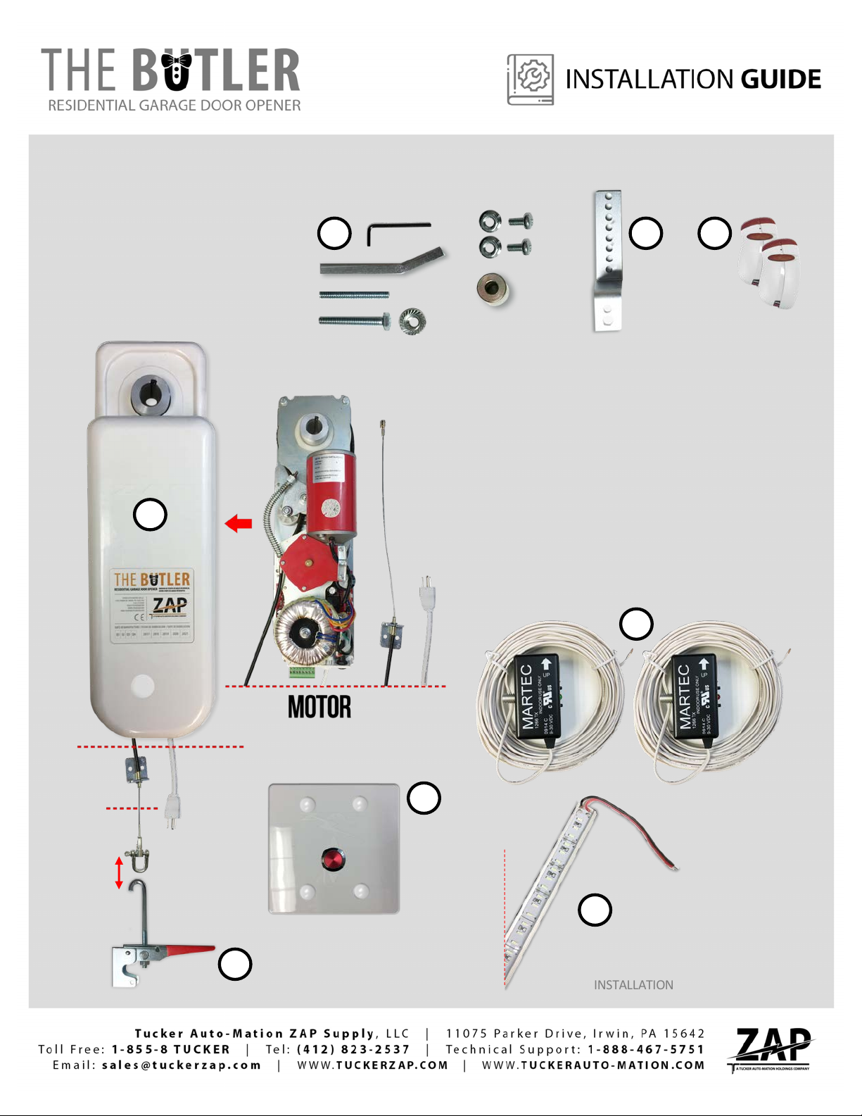
OPERATOR PACKAGE
THE BUTLER
115V 50/60 c/s
For Standard Lift Doors Up To 280 Sq. Ft.
YOUR PRIVATE GARAGE DOOR Incorporating
SAFETYSENSE
TM
A. BUTLER OPERATOR
B. TOOL KIT
C. WALL BUTTON
D. HARDWARE
E. OVERRIDE LEVER
(MANUAL RELEASE)
F. 2 TRANSMITTER KEY
(WITH VISOR)
G. PHOTO-EYES
(SAFETY BEAM SENSORS)
H. LED LIGHT STRIP
A
B
G
D F
E
C
H
Page 6
INSTALLATION GUIDE 920.1037.03 | 06
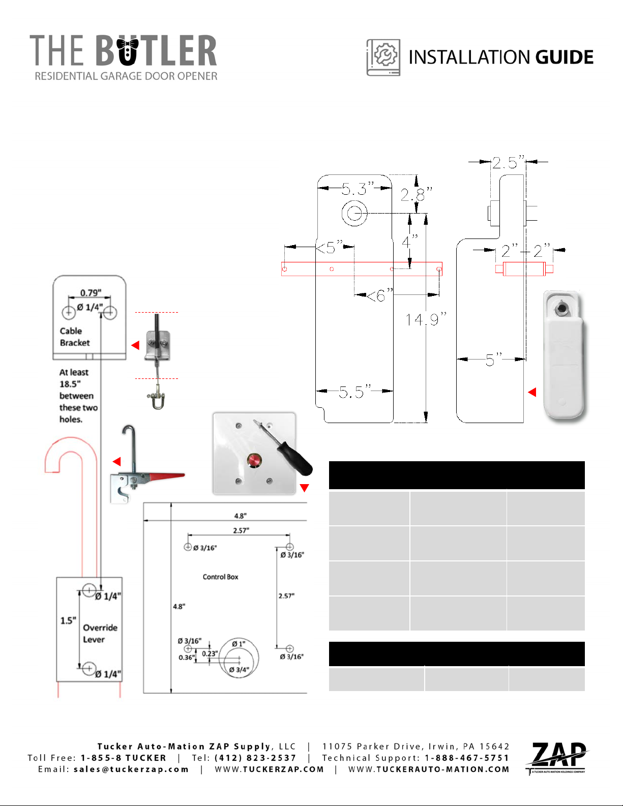
DIMENSIONS
THE BUTLER
115V 50/60 c/s
For Standard Lift Doors Up To 280 Sq. Ft.
YOUR PRIVATE GARAGE DOOR Incorporating
SAFETYSENSE
TM
The Torque Arm fixing range is shown in RED
MAXIMUM DOOR SIZES
Standard lift:
280
sq ft. or 1280 lb.
5.25” drum
diameter
High lift up to 54”:
210
sq ft. or 960 lb.
7.5” drum
diameter
High lift greater
than 54”:
144
sq ft. or 660 lb.
9.38” drum
diameter
Vertical lift:
165
sq ft. or 750 lb.
8.63” drum
diameter
WALL BUTTON
- CONTROL BOX
4.8” H
4.8” W
2.5” D
BUTLER OPERATOR
WALL BUTTON
OVERRIDE
LEVER
Page 7

INSTALLATION GUIDE 920.1037.03 | 07
OPERATOR INSTALLATION
THE BUTLER
115V 50/60 c/s
For Standard Lift Doors Up To 280 Sq. Ft.
YOUR PRIVATE GARAGE DOOR Incorporating
SAFETYSENSE
TM
(Pic 1.1).
PIC 1.1
PIC 1
Installation of THE BUTLER is as simple as it gets. It only requires one person with a ladder to install the motor assembly on the spring shaft.
Nothing mounts to the ceiling, door jamb, or header area, so your garage or shop stay sleek looking. All you need is to power it up by plugging it
into a nearby outlet in your garage or shop. Now it’s just a matter of running the door open and close two times with THE BUTLER and it will set
it’s fully open and closed positions for you. You just stand back and watch!
Page 8

With the door fully open, rotate the door shaft to ensure that the
door will roll forwards under its own weight. (Pic 2). If it won’t then
raise the rear of the track or fit a set of buffer springs. Vertical lift
doors may require a set of buffer springs to provide a physical end
stop.
INSTALLATION GUIDE 920.1037.03 | 08
STEP 01 - BEFORE INSTALLING THE OPERATOR
PIC 2
Next, move the door by hand from
closed to open and back to closed
again. Check that it is either perfectly
balanced or biased slightly open if
perfect balance can’t be achieved. If
the door movement is stiff at any
point, the cause of the problem
should be identified and fixed by a
qualified person. The door must
move smoothly by hand pressure
without significant force or sudden
changes in the effort required to
move the door. (Pic 3).
PIC 3
Page 9

INSTALLATION GUIDE 920.1037.03 | 09
STEP 02 - OPERATOR MOUNTING
/ LEFT MOUNT OR RIGHT MOUMT
- RIGHT OR WRONG LABELS
INTERIOR
GARAGE
DOOR
INTERIOR
GARAGE
DOOR
INTERIOR
GARAGE
DOOR
INTERIOR
GARAGE
DOOR
LEFT MOUNT LEFT MOUNT
RIGHT MOUNT
RIGHT MOUNT
HANDED GARAGE DOOR OPERATOR. IT IS CRITICAL TO RESPECT THE
LABELING. INSTALL TO THE LEFT OR TO THE RIGHT SIDE OF THE DOOR BY
FOLLOWING THE LABEL INDICATION!
Page 10

INSTALLATION GUIDE 920.1037.03 | 10
STEP 03 - GENERAL INSTALLATION
Slide the Control Head onto the jackshaft and select a hole on the
bearing plate or door frame for the torque arm. ((A)-Pic 4.1). If no
hole is available then drill a 1/4” hole in a suitable location. Bolt the
torque arm to the bearing plate or door frame and secure the other
end to the torque arm fixing the hole on the Control Head, use the
supplied spacer if the offset is not enough to clear the drum. (Pic
4.1).
A
PIC 4
THE BUTLER kit includes an anti-rotation torque arm; it is possible to mount the Control Head inboard or outboard
the bearing plates and horizontally or vertically so long as the torque arm is at right angles to the operator. This
stops the operator from moving side to side when the door is moving. ((B)-Pic 5.1).
A
B
ANTI-ROTATION TORQUE ARM
PIC 4.1
90°
B
PIC 5.1
PIC 5
B
+ KIT TO ATTACH TO DOOR TRACK
B
Page 11

INSTALLATION GUIDE 920.1037.03 | 11
C
Align the Control Head driven pulley’s keyway with
the door shaft keyway and fit the supplied key.
Ensure that the Allen screws are firmly tight and
then tighten the lock nuts. ((C)-Pic 6).
PIC 6
If there is no keyway, the hollow door shaft should be drilled. Tighten
one Allen screw to mark the shaft through the screw hole, remove the
Control Head and drill through one wall of the shaft with a 1/4” drill bit.
Replace the keyway Allen screw with the long Allen screw supplied. Refit
the Control Head and re-tighten the torque arm bolts. Align the long
screw with the drilled hole in the shaft and tighten it against the inside
wall of the shaft. Tighten the other Allen screw and both of the lock
nuts. (Pic 7).
C
PIC 7
OPTIONAL – SHAFT EXTENDER IF NEEDED!
SHAFT EXTENDER:
In case the shaft on either side of the garage door does not show at least
3”, you will need a shaft extender to introduce inside hollow metal tube
(Pic 7.1).
TYPES:
a) 1” Hollow shaft extender
b) 1
1/4
” Hollow shaft extender
PIC 7.1
INTERIOR
GARAGE
DOOR
a b
a
Page 12

INSTALLATION GUIDE 920.1037.03 | 12
STEP 04 - FITTING THE MANUAL OVERRIDE LEVER MECHANISM
Drill two 1/4” holes in the door track or frame in a position at least
2” higher than the fully extended position of the Outer Cable
Bracket to allow flexibility of movement for the Bowden cable. Use
the supplied M5 screws and flange nuts to secure the Outer Cable
Bracket to the door track or frame. (Pic 8).
Hang the Manual Override Lever hook on the end of the inner cable
with the lever in the upright position. Mark the mounting hole
positions for the lever on the door track or frame – the supplied
chain may be needed to position the lever withi n 6 feet of the floor.
Drill two 1/4” holes and secure the lever using the M5 screws and
flange nuts supplied. (Pic 9).
PIC 9
PIC 8
M5 screws
M5 screws
MOUNTING HOLE
MOUNTING HOLE
OVERRIDE
LEVER
Page 13

INSTALLATION GUIDE 920.1037.03 | 13
Place the hook in the cable D-shackle or a convenient link of the chain and ensure that the lever
is slightly above horizontal when all of the tension has been taken up. (Pic 10).
It is important that sufficient tension is achieved to compress the override release spring and
ensure that the drive belt does not slip on the motor pulley. Screw the hook in or out so that the
lever requires reasonable hand pressure to lock it into place. (Pic 11). This procedure must be
repeated once the calibration has been completed and on subsequent service visits to allow for
the bedding inof the V-belt.
PIC 11
PIC 10
MOUNTING HOLE
OFF = MANUAL
SIDE VIEW
MOUNTING HOLE
ON = AUTOMATIC
SIDE VIEW
FRONT VIEW
ON = AUTOMATIC
OFF = MANUAL
Page 14

INSTALLATION GUIDE 920.1037.03 | 14
STEP 05 - FITTING THE WALL BUTTON BOX
Mount the box on the wall using suitable fasteners no larger than 3/16” diameter. (Pic 12).
Connect the battery. (Pic 12.1).
AFTER BUTLER OPERATOR AND WALL BUTTON BOX
INSTALLED. HOLD THE WALL BUTTON AND THE RECEIVER
BUTTON TOGETHER FOR 5 SECONDS UNTIL BEEP !
BEEP!
STEP 06 - WALL BUTTON - CONNECTION
HOLD THE WALL BUTTON
HOLD THE RECEIVER BUTTON
PIC 12.1
PIC 12
Page 15

INSTALLATION GUIDE 920.1037.03 | 15
STEP 07 – TRANSMITTER KEY CONNECTION
AFTER BUTLER OPERATOR AND WALL BUTTON BOX
INSTALLED. HOLD THE TRANSMITTER KEY AND THE
RECEIVER BUTTON TOGETHER FOR 5 SECONDS UNTIL
BEEP !
BEEP!
HOLD THE TRANSMITTER
KEY BUTTON
HOLD THE RECEIVER BUTTON
Page 16

INSTALLATION GUIDE 920.1037.03 | 16
STEP 08 – LED LIGHTS INSTALLATION & CONNECTION
INSTALLED TOP RAIL
INSTALLED
FRONT RAIL
OR
36 Inches Long
D
C C
E
LED LIGHTS
CONNECTION:
D. LED LIGHT (+) (RED WIRE)
E. LED LIGHT (-) (BLACK WIRE)
(Stay “ON” for 5 min after activation).
STEP 09 - SAFETY SENSORS INSTALLATION & CONNECTION
THE BUTLER
SAFETY SENSORS
CONNECTION:
A. SAFETY SENSOR 1
A. SAFETY SENSOR 1
B. SAFETY SENSOR 2
B. SAFETY SENSOR 2
A A
B B
D E
WIRE PUSH PLATE IF NEEDED!
A A B B
A A B B
Page 17

INSTALLATION GUIDE 920.1037.03 | 17
Monthly: check that the closing door reverses when the safety sensor
beam is interrupted . Monthly: ensure that the garage door reverses on
contact with a 1.5 inch high object (or a 2” by 4” board laid flat) on the
floor.
During winter: if the door reversesoff a build up of snow or ice then the
doorway should enable the door to close fully.
Every 6 months or 2500 cycles whichever is sooner:
1. Release the Manual Override Lever and move the door manually to
assess the balance of the door and to check if it is binding. (Pic 13).
2. Check the adjustment of the Manual Override Lever tension. The lever
should be horizontal when the release spring is compres s e dand the drive
belt slack is taken up. If the lever tension requires increasing then turn the
lever hook screw clockwise to increase the tension. Do not over-tension
the Manual Override Lever. (Pic 14).
3. Check that the door opens and closes fully.
The motor operator does not require additional lubrication. Do not grease
the door tracks. If there is any doubt about the correct operation of the
door then contact your garage door/opener dealer.
PIC 13
MAINTENANCE SCHEDULE
PIC 14
 Loading...