

Tucker SW10, SW19 Installation Manual

!
920.1020.15
1
!
!
!
!
!
!
!
!
!
!
!
TUCKER AUTO-MATION
SW10 (Full Power) & SW19 (Low Energy)
INSTALLATION GUIDE
Surface Mounted Applications
!
!

!
920.1020.15
2
PAGE
CONTENTS
3
Important Notices
4
Product Description & Specifications
5-10
Header Installation
11-14
Mounting The Operator & Control Assembly
15-17
Push Arm Installation
17-18
Pull Arm Installation 19
120 Volt AC Connection
20
Power On & Indications
21-24
Set-Up Procedures
25
Wiring Connections
26
Adjusting The Mechanical Door Stop
27
Troubleshooting
28
Job Documentation & Closeout / Accessories / Company Contact
29-31
Appendix - Wiring Diagrams
32-33
Appendix - Fire Rated Door Application
25 (KP EVO 1-25)
Appendix - Tap Programming Device - KP evo
!
TABLE OF CONTENT
S:
!
!

!
920.1020.15
3
!
IMPORTANT
READ THIS SECTION BEFORE PROCEEDING WITH INSTALLATION
Tucker Auto-Mation, LLC (hereafter referred to as “Tucker”) recommends that all of its automated
pedestrian door products be installed by a trained automatic door technician and that the resulting
performance of the product be in full compliance with the most current version of the American National
Standards Institute document A156.10 or A156.19 (whichever is applicable) as well as any applicable building
codes and/or fire codes. Tucker further recommends that a full inspection of the operating system be
performed in accordance with the guidelines of the American Association of Automatic Door manufacturers
(AAADM). This inspection must be performed by a certified AAADM trained inspector. Tucker recommends
this documented inspection be performed upon completion of the installation as well as, following the
completion of every service call thereafter. If service is not performed within one year of the previous service
action, a routine AAADM inspection should be performed and documented. Under no circumstance should
the product operate for more than one year without an AAADM inspection. Tucker does NOT recommend
installation or service, on any of their automated pedestrian door products, by any individual who is not
certified as an AAADM inspector.
Following the installation or service of any Tucker automated pedestrian door product, if it is deemed unsafe,
or is operating in an unsatisfactory manner according to national performance standards or recommended
performance guidelines as defined by Tucker, repairs should be made immediately. If an immediate repair
cannot be made, the product should be disabled, and appropriate measures should be taken to secure the
door in a safe position or to enable the door to safely be used manually. During this situation, every effort
should be made to notify the owner (or person responsible) of the condition and to advise on corrective
actions that must be taken to return the product to safe operation.
LOW ENERGY APPLICATION NOTE
When using the SW10/19 for a low energy application, Tucker Auto-Mation recommends the use of a doormounted presence sensor on the approach side of the door to be used as a secondary activation device. This
type of sensor can be installed at time of installation or can also be retrofitted. This device serves to re-activate
the door to the open position should a person enter into the closing path at the approach side of the door, as
it is closing. Once the door is fully closed, a "knowing act" device must then be used for initial activation.
Tucker Auto-Mation considers this device to be essential in reducing the possibility of doors "timing out" and
closing before all pedestrians have passed though the doorway. Check with your Tucker sales representative
to find out about special incentives that may be available for the Torpedo 1 door-mounted presence sensor.
!
!
!

!
920.1020.15
4
Power Supply
115
VAC (+6%, -10%)
60Hz
Power Consumpti
on
100W
C
urrent Consumpti
on
1A
Mot
or
24
VDC
Permanent Magnet
With Belt Driven Encoder
Header Dimensions
20 3/4” x 4 1/8” x 4 3/4”
(l
x w x d)
Fused Protection
3.5A Fuse (F1 locate
d on I/O Board)
Weight
22
lbs
Per Operator Assembly
Ambient Operating Temperature
-4 to 131º F
Ingress Protection
IP23 (protection from spray water up to 60º from th
e
vertical – ie. Rainst
orm)
Maximum
Door Weight
PUSH ARM
PULL ARM
36” Door: 438
lbs
342 lbs
42” Door: 328
lbs
256 lbs
44” Door: 299
lbs
234 lbs
48” Door: 254
lbs
198 lbs
24
VDC Accessories Power Supply
24
VDC
/
I A. Max
24
VDC Electric Lock
Power Supply
24
VDC
/
I A. Max
Adjustable Speeds & Timers
Opening Speed
Closing Speed
Hold
Open Tim
e
Closing Speed
with power off
Standa
rd Select
or Switch Functions
Automati
c
Hold O
pen
Manual
(Off)
Standa
rd Control Outputs
Malfunction
Alarm Signal
Electric Lock
Relay
24
VDC Accessories Power Supply
Door
Status
Standa
rd Control Inputs
Interior Activati
on
Exterior Activati
on
Emergency Shutdow
n
Alarm Output
“Stop” Safety Device (door-mounted)
Safety Device Inpu
t
Secondary Activation
Quick Disconnects
TAP-Controller (optional)
!
PRODUCT DESCRIPTION & SPECIFICATIONS
The Tucker Auto-Mation SW10 & drives. The unique design offers; non-including sensors, push plates, fire
alarm, and electric locks. Troubleshooting when needed. Both units can be configured concealed application.
The Tucker Advanced Programmer (TAP) is provided as an option to access additional programming features.
!
!
!
!
!
!

!
920.1020.15
5
PUSH ARM APPLICATIONS:
Bottom of header is flush with bottom of top
frame.
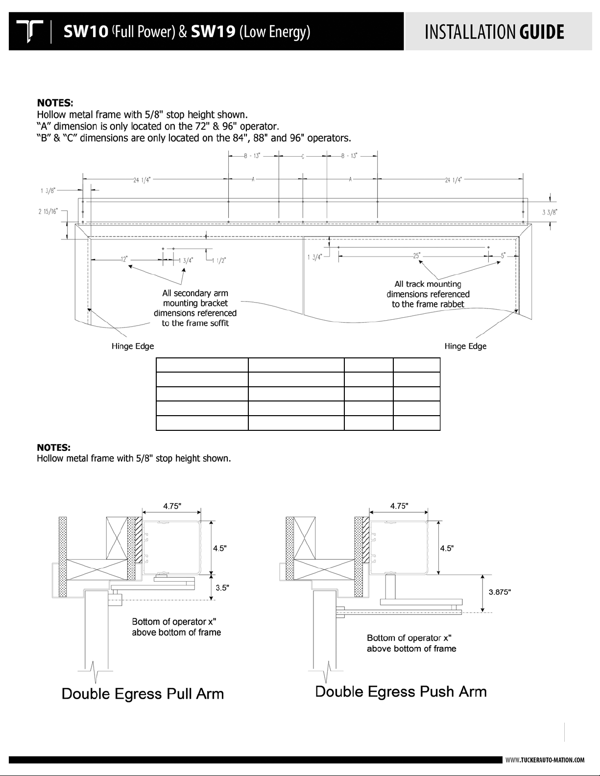
PULL ARM APPLICATION: STANDARD PULL ARM
& DOUBLE EGRESS APPLICATIONS
Double egress applications require the use of an
80mm spindle adaptor for the side using the
push arm.
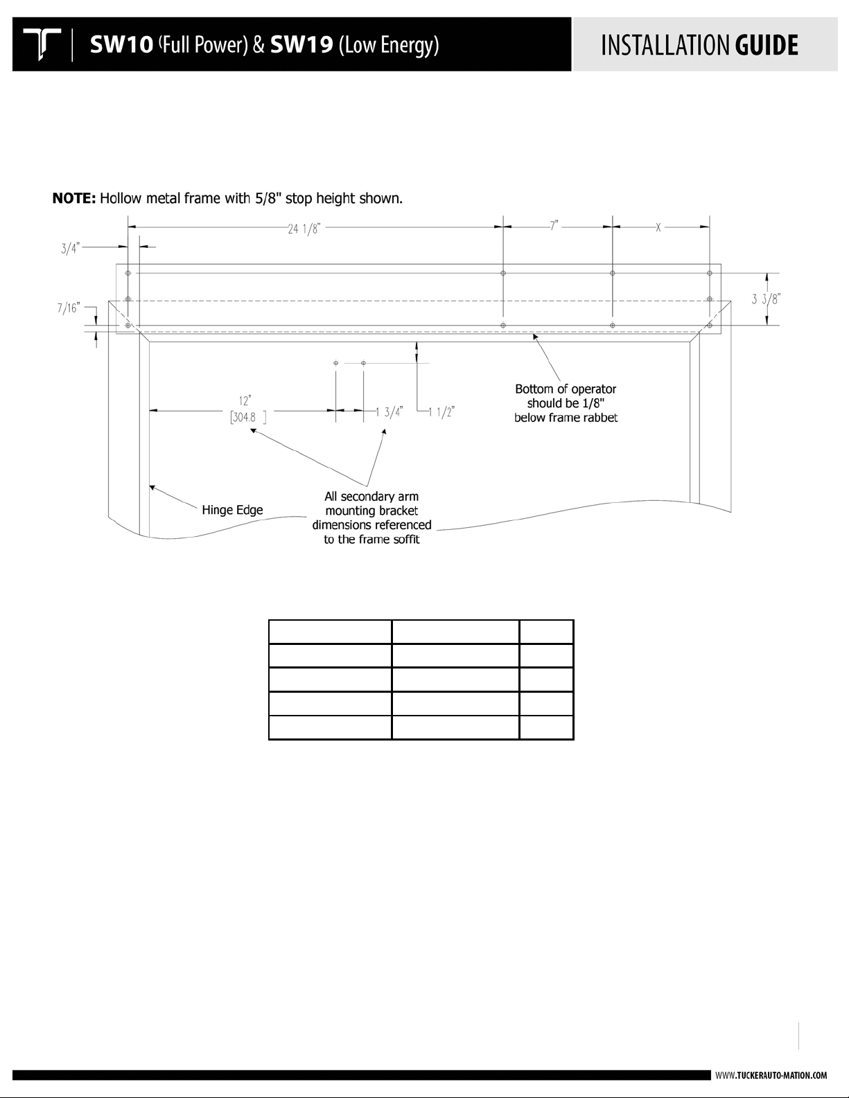
NOTE:
Tucker Auto-Mation is now using a 35mm
spindle adaptor for all standard push arm
applications – this requires that the header
assembly be mounted as shown at left, flush
with bottom of top frame.
!
!
!
HEADER INSTALLATION
Mount the pre-drilled back-plate to the top door frame using appropriate fasteners for the type of
frame. (Refer to Door Prep drawings on pgs. 6-10.)
• Push side mounting: Pre-drilled back-plate is flush with bottom of door frame.
• Pull side mounting: Pre-drilled back-plate is mounted 1.5” up from bottom door frame.
• Back-plate should overlap each jamb tube by 1.5”.
• Refer to the APPENDIX for fire rated door applications.
!
!
!
!
!
!
!
!
!
!
!
!
!
!
!
!
!
!
!
!
!
!
!
!
!
920.1020.15
6
Opening Width
Operator Width
X Dim
36"
39"
6.25"
42"
45"
12.25" 44"
47"
14.25"
48"
51"
18.25"
!
Door Prep drawings:
PUSH SIDE INSTALLATION SINGLE
!
!
!
920.1020.15
7
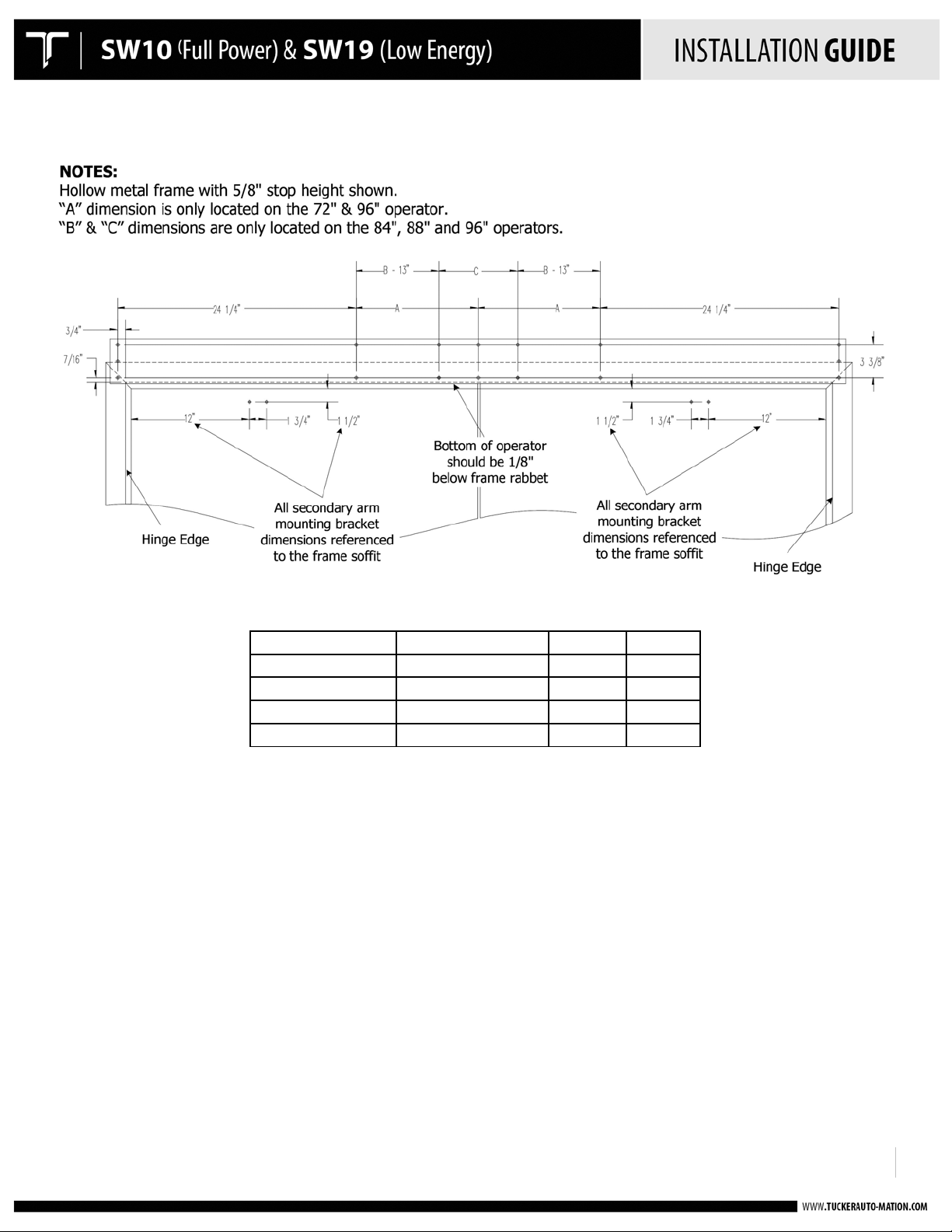
Opening Width
Operator Width
A Dim
C Dim
72" 75"
12-7/16"
N/A
84" 87"
N/A
10-7/8"
88" 91"
N/A
14-7/8"
96" 99"
24-7/16"
22-7/8"
!
PUSH SIDE INSTALLATION DOUBLE
!
!

!
920.1020.15
8
Opening Width
Operator Width
Y Dim 36"
39"
6.25"
42"
45"
12.25" 44"
47"
14.25" 48"
51"
18.25"
!
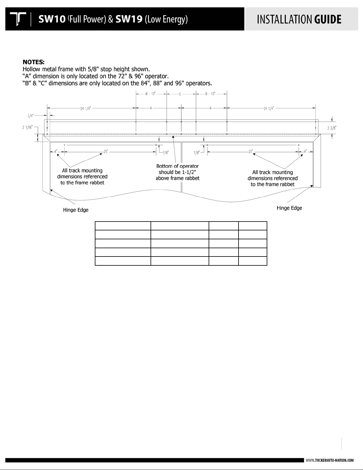
PULL SIDE INSTALLATION SINGLE
!
!
!
920.1020.15
9
Opening Width
Operator Width
A Dim
C Dim 72" 75"
12-7/16"
N/A
84" 87"
N/A
10-7/8"
88" 91"
N/A
14-7/8"
96" 99"
24-7/16"
22-7/8"
!
PULL SIDE INSTALLATION DOUBLE
!
!
!
920.1020.15
10
Opening Width
Operator Width
A Dim
C Dim 72" 75"
12-7/16"
N/A
84" 87"
N/A
10-7/8" 88" 91"
N/A
14-7/8"
96" 99"
24-7/16"
22-7/8"
!
DOUBLE EGRESS INSTALLATION
!
!
!
920.1020.15
11
!
MOUNT THE OPERATOR(S)!!
!
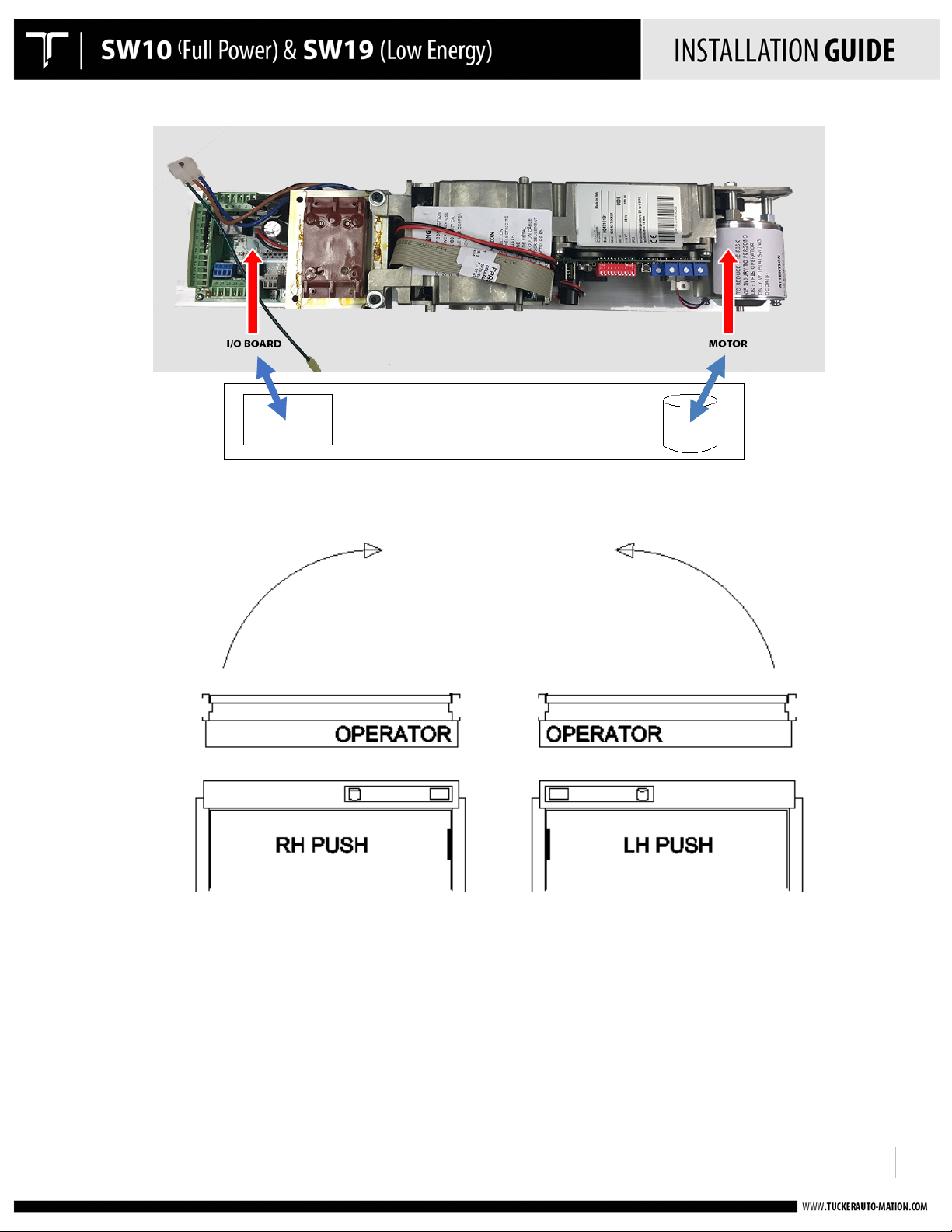
• Operator is non-handed – same operator for all hands of doors
• Handing is determined by how the operator is mounted inside the header
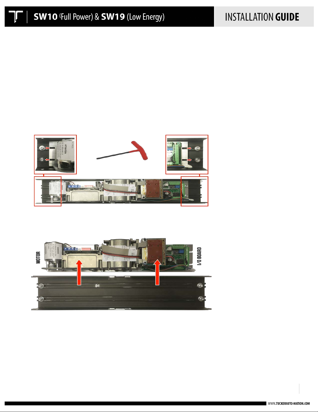
• The operator is mounted to a short aluminum “drive” plate that is held into the header by 5 mounting screws.
Four (4) of the screws secure the drive plate. One (1) screw is used to locate the drive plate using a ‘keyhole’
configuration. The keyhole allows for easy removal of the drive plate without the need to loosen to screw.
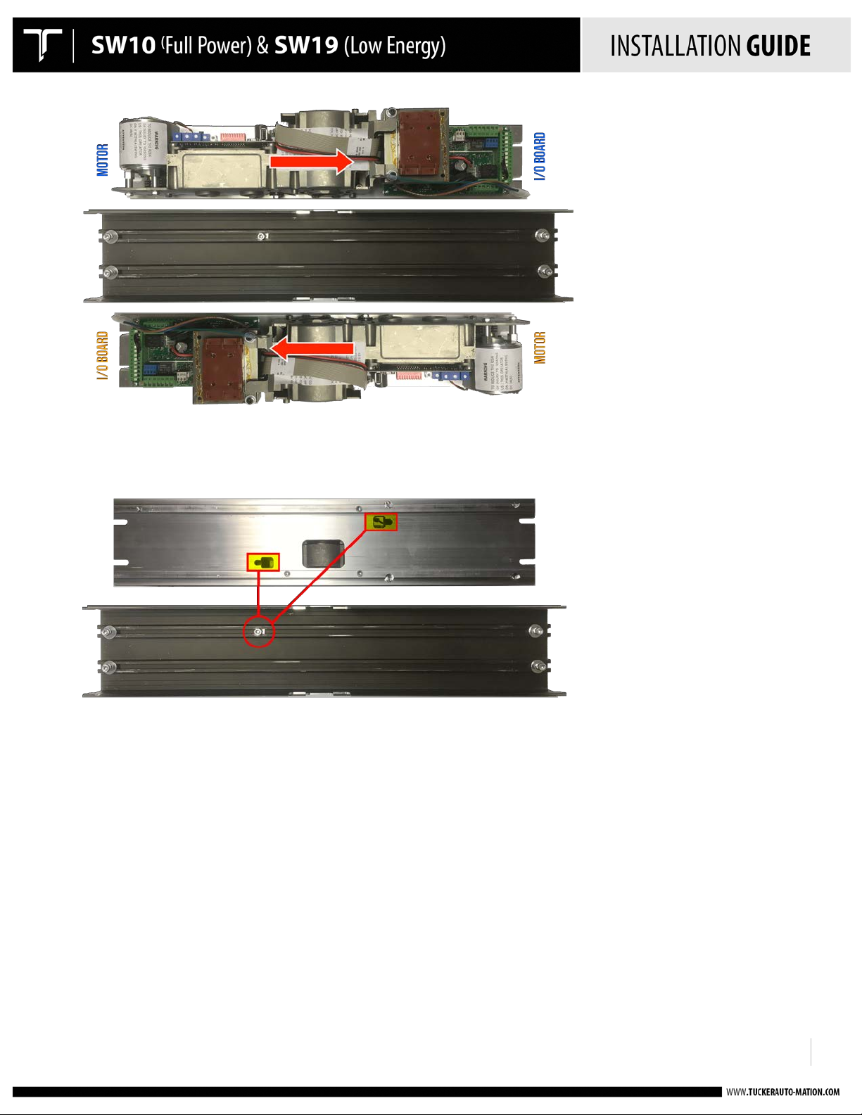
Removing the four (4) screws allows the drive plate & operator to be removed from the header and rotated 180
degrees to change from a push to a pull or vice versa.
!
Drive Plate mounted in standard position using four (4) screws to secure. Loosen the screws using an 5 mm allen
wrench and slide each one off of the drive plate.
!
Drive plate removed by shifting to the left and lifting the drive plate off of the locating screw.
!
!
!
!
!
!
!
!
!
!
920.1020.15
12
!
!
!
!
Drive plate rotated 180 degrees to reverse the operator handing. Re-align locating screw to key slot, insert drive plate
and shift to the right into position. Re-position the four (4) screws to secure the drive plate.
!
Key slot configuration & location screw mounted in backplate
!
!
!
!
!
!
!
!
!
!
!
!
!
!
!
!
920.1020.15
13
PUSH = I/O BOARD IS TOWARDS THE HINGE JAMB
!
!
!
!
!
!
!
!
!
!
!
!
!
!
!
!
!
!
!
!
!
!
!
!
!
!
!
!
!
!
!
!
!
!
!
!
!
!
!
!
!
!
!
!
!
!
!
!
!
!

!
920.1020.15
14
!
!
!
!
!
!
!
!
!
!
!
!
!
!
!
!
!
!
!
!
!
!
!
!
!
!
!
!
• Mount the header to the doorframe with the screws provided.
• The header will overlap the doorframe by 1-1/2" at each side.!
!
!
!
!
!
920.1020.15
15
!
!
!
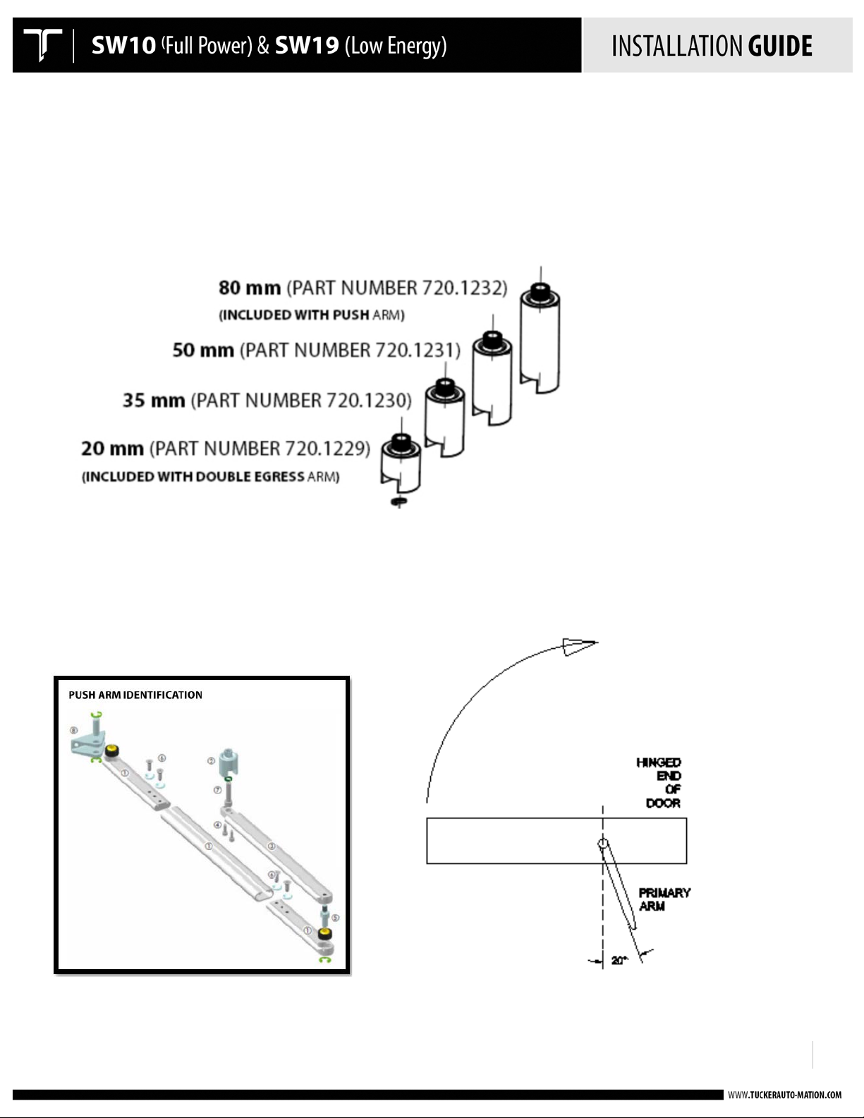
PUSH ARM INSTALLATION
• All push arms come standard with 35mm spindle. 50mm and 80mm available as an accessory.
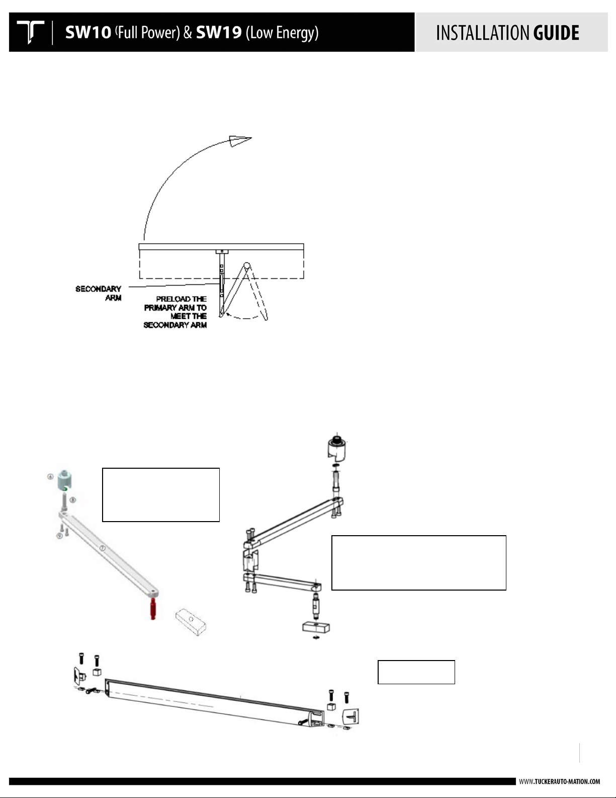
• Attach the primary door arm approx. 20 degrees past perpendicular and towards the closing direction as shown.
If more spring tension is desired, simply increase the mounting angle to greater than 20 degrees so it results in
increased preload.
!
!
!
920.1020.15
16
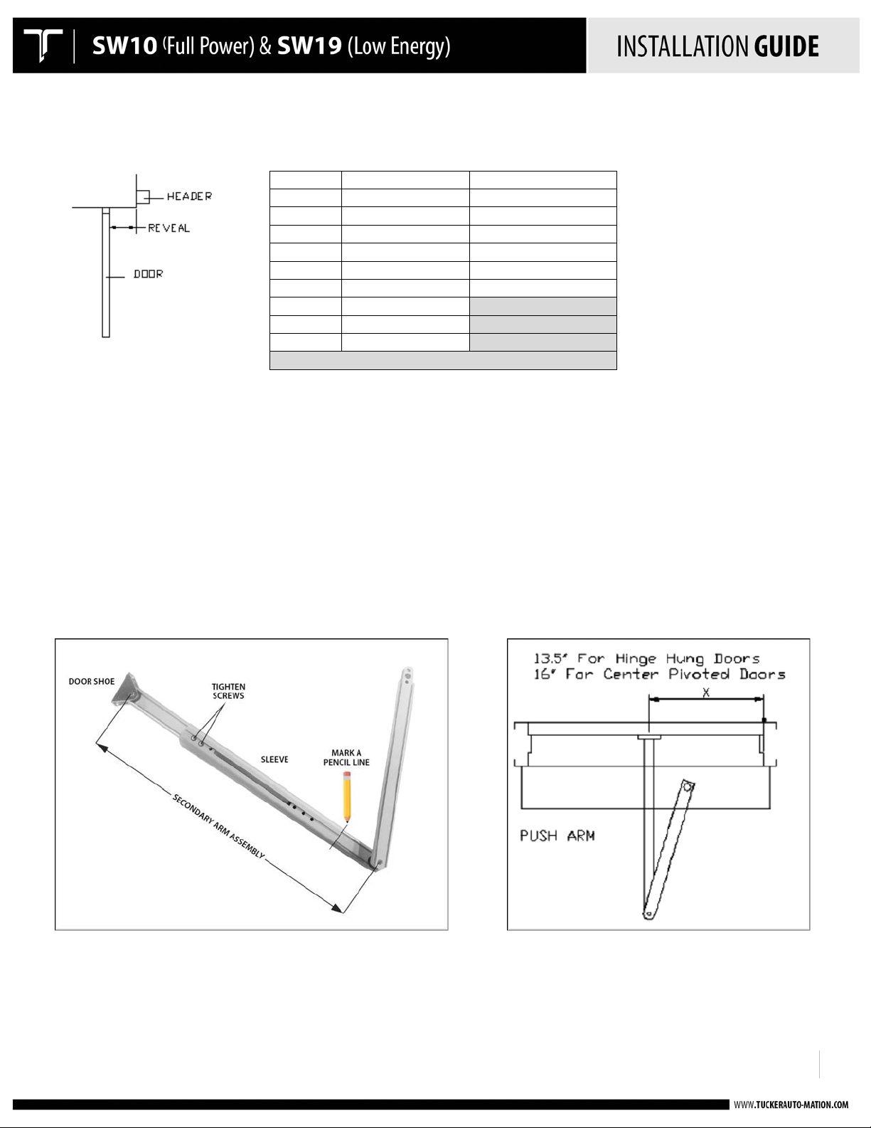
Reveal
Hinge Hung X Dim.
Center Pivot X Dim.
0
" 13
" 16
"
1
" 14
" 17
"
2
" 15
" 18
"
3
" 16
" 19
"
4
" 17
" 20
"
5
" 18
" 21
"
6
" 19
"
7
" 20
"
8
" 21
"
DEEPER REVEAL
REQUIRES ARM EXTENSION
!
• Adjust the secondary telescopic arm to the prescribed length according to chart:
Before installing
•
insert the secondary and primary arm into the sleeve as it will
Slide
o
o
o
o Mark a
• Attach the secondary arm mounting bracket to the door. The centerline of the bracket should be at 13-1/2” in
from the inside face of the hinge jamb when using butt hinges on the door, and 16” when using a center pivoted
door.
the short arms within the sleeve to obtain the prescribed
Tighten the screws on the short arm that
Double-check
r shoe and the center of the hole
doo
imary
pr
any porti
the
pencil line
arm.
This will
on of the door arm assembly, it is easiest to
be when installed on the door:
is
connected to the door shoe.
"X" dimension of the arm - this is
at the pivot
at the edge of the sleeve where it overlaps
make it easie
r when positioning
the distance between the center of the hole
point of the primary arm (as shown).
the primary arm for
lay
the arm out on a flat
"X" dimension.
the short arm that
final installation.
is
connected to the
surface and
at the
!
!
!
920.1020.15
17
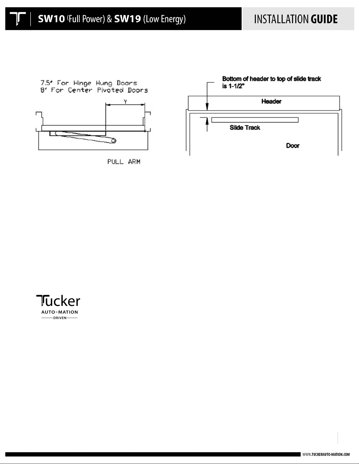
Standard Pull Arm
For 0-degree reveal
Use 20mm spindle
Offset (double egress) Pull Arm
For reveal greater than 0 degrees
Use 20mm Spindle
Slide Track
!
• Rotate the primary arm in the opening direction as to reach the pivot point of the secondary. Attach the arms
together with the hardware provided.
PULL ARM INSTALLATION
!
!
!
920.1020.15
18
!
• Install the slide track assembly at the pull side of the door at the proper location from the hinge end of the door
as shown below:
• To install the pull arm, the operator must be powered to the full open position, as it is not possible to install the
arm in the closed position as to allow proper preload.
• Power the door to the open position through the use of the hold-open switch on the side of the header. It may
be necessary to first execute a “setup” on the operator prior to doing this. Refer to the applicable section within
this User’s Guide for proper instruction.
• Once the operator is rotated to the full open position, manually move the door to the desired full open position
and insert the slide track guide block into the track. When completed, the end caps to the track can be installed.
!
!
 Loading...