

Page 1

!
920.1020.15
1
!
!
!
!
!
!
!
!
!
!
!
TUCKER AUTO-MATION
SW10 (Full Power) & SW19 (Low Energy)
INSTALLATION GUIDE
Surface Mounted Applications
!
!
Page 2

!
920.1020.15
2
PAGE
CONTENTS
3
Important Notices
4
Product Description & Specifications
5-10
Header Installation
11-14
Mounting The Operator & Control Assembly
15-17
Push Arm Installation
17-18
Pull Arm Installation 19
120 Volt AC Connection
20
Power On & Indications
21-24
Set-Up Procedures
25
Wiring Connections
26
Adjusting The Mechanical Door Stop
27
Troubleshooting
28
Job Documentation & Closeout / Accessories / Company Contact
29-31
Appendix - Wiring Diagrams
32-33
Appendix - Fire Rated Door Application
25 (KP EVO 1-25)
Appendix - Tap Programming Device - KP evo
!
TABLE OF CONTENT
S:
!
!
Page 3

!
920.1020.15
3
!
IMPORTANT
READ THIS SECTION BEFORE PROCEEDING WITH INSTALLATION
Tucker Auto-Mation, LLC (hereafter referred to as “Tucker”) recommends that all of its automated
pedestrian door products be installed by a trained automatic door technician and that the resulting
performance of the product be in full compliance with the most current version of the American National
Standards Institute document A156.10 or A156.19 (whichever is applicable) as well as any applicable building
codes and/or fire codes. Tucker further recommends that a full inspection of the operating system be
performed in accordance with the guidelines of the American Association of Automatic Door manufacturers
(AAADM). This inspection must be performed by a certified AAADM trained inspector. Tucker recommends
this documented inspection be performed upon completion of the installation as well as, following the
completion of every service call thereafter. If service is not performed within one year of the previous service
action, a routine AAADM inspection should be performed and documented. Under no circumstance should
the product operate for more than one year without an AAADM inspection. Tucker does NOT recommend
installation or service, on any of their automated pedestrian door products, by any individual who is not
certified as an AAADM inspector.
Following the installation or service of any Tucker automated pedestrian door product, if it is deemed unsafe,
or is operating in an unsatisfactory manner according to national performance standards or recommended
performance guidelines as defined by Tucker, repairs should be made immediately. If an immediate repair
cannot be made, the product should be disabled, and appropriate measures should be taken to secure the
door in a safe position or to enable the door to safely be used manually. During this situation, every effort
should be made to notify the owner (or person responsible) of the condition and to advise on corrective
actions that must be taken to return the product to safe operation.
LOW ENERGY APPLICATION NOTE
When using the SW10/19 for a low energy application, Tucker Auto-Mation recommends the use of a doormounted presence sensor on the approach side of the door to be used as a secondary activation device. This
type of sensor can be installed at time of installation or can also be retrofitted. This device serves to re-activate
the door to the open position should a person enter into the closing path at the approach side of the door, as
it is closing. Once the door is fully closed, a "knowing act" device must then be used for initial activation.
Tucker Auto-Mation considers this device to be essential in reducing the possibility of doors "timing out" and
closing before all pedestrians have passed though the doorway. Check with your Tucker sales representative
to find out about special incentives that may be available for the Torpedo 1 door-mounted presence sensor.
!
!
!
Page 4

!
920.1020.15
4
Power Supply
115
VAC (+6%, -10%)
60Hz
Power Consumpti
on
100W
C
urrent Consumpti
on
1A
Mot
or
24
VDC
Permanent Magnet
With Belt Driven Encoder
Header Dimensions
20 3/4” x 4 1/8” x 4 3/4”
(l
x w x d)
Fused Protection
3.5A Fuse (F1 locate
d on I/O Board)
Weight
22
lbs
Per Operator Assembly
Ambient Operating Temperature
-4 to 131º F
Ingress Protection
IP23 (protection from spray water up to 60º from th
e
vertical – ie. Rainst
orm)
Maximum
Door Weight
PUSH ARM
PULL ARM
36” Door: 438
lbs
342 lbs
42” Door: 328
lbs
256 lbs
44” Door: 299
lbs
234 lbs
48” Door: 254
lbs
198 lbs
24
VDC Accessories Power Supply
24
VDC
/
I A. Max
24
VDC Electric Lock
Power Supply
24
VDC
/
I A. Max
Adjustable Speeds & Timers
Opening Speed
Closing Speed
Hold
Open Tim
e
Closing Speed
with power off
Standa
rd Select
or Switch Functions
Automati
c
Hold O
pen
Manual
(Off)
Standa
rd Control Outputs
Malfunction
Alarm Signal
Electric Lock
Relay
24
VDC Accessories Power Supply
Door
Status
Standa
rd Control Inputs
Interior Activati
on
Exterior Activati
on
Emergency Shutdow
n
Alarm Output
“Stop” Safety Device (door-mounted)
Safety Device Inpu
t
Secondary Activation
Quick Disconnects
TAP-Controller (optional)
!
PRODUCT DESCRIPTION & SPECIFICATIONS
The Tucker Auto-Mation SW10 & drives. The unique design offers; non-including sensors, push plates, fire
alarm, and electric locks. Troubleshooting when needed. Both units can be configured concealed application.
The Tucker Advanced Programmer (TAP) is provided as an option to access additional programming features.
!
!
!
!
!
!
Page 5

!
920.1020.15
5
PUSH ARM APPLICATIONS:
Bottom of header is flush with bottom of top
frame.
PULL ARM APPLICATION: STANDARD PULL ARM
& DOUBLE EGRESS APPLICATIONS
Double egress applications require the use of an
80mm spindle adaptor for the side using the
push arm.
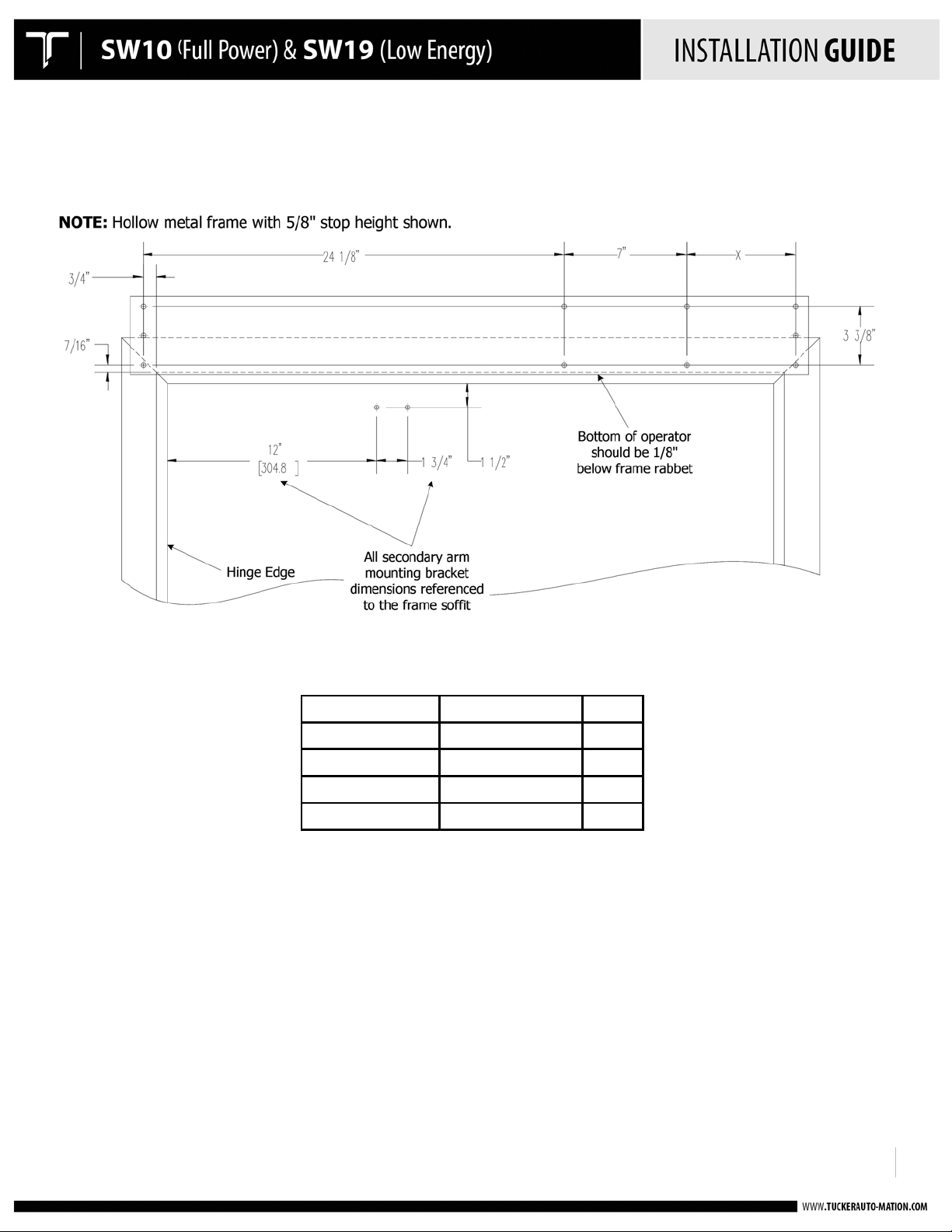
NOTE:
Tucker Auto-Mation is now using a 35mm
spindle adaptor for all standard push arm
applications – this requires that the header
assembly be mounted as shown at left, flush
with bottom of top frame.
!
!
!
HEADER INSTALLATION
Mount the pre-drilled back-plate to the top door frame using appropriate fasteners for the type of
frame. (Refer to Door Prep drawings on pgs. 6-10.)
• Push side mounting: Pre-drilled back-plate is flush with bottom of door frame.
• Pull side mounting: Pre-drilled back-plate is mounted 1.5” up from bottom door frame.
• Back-plate should overlap each jamb tube by 1.5”.
• Refer to the APPENDIX for fire rated door applications.
!
!
!
!
!
!
!
!
!
!
!
!
!
!
!
!
!
!
!
!
!
!
!
!
Page 6
!
920.1020.15
6
Opening Width
Operator Width
X Dim
36"
39"
6.25"
42"
45"
12.25" 44"
47"
14.25"
48"
51"
18.25"
!
Door Prep drawings:
PUSH SIDE INSTALLATION SINGLE
!
!
Page 7
!
920.1020.15
7
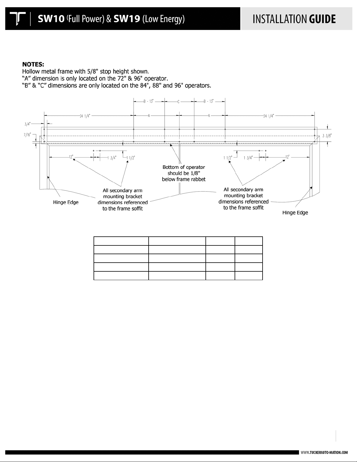
Opening Width
Operator Width
A Dim
C Dim
72" 75"
12-7/16"
N/A
84" 87"
N/A
10-7/8"
88" 91"
N/A
14-7/8"
96" 99"
24-7/16"
22-7/8"
!
PUSH SIDE INSTALLATION DOUBLE
!
!
Page 8

!
920.1020.15
8
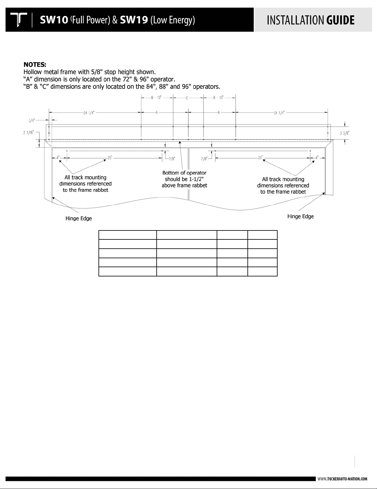
Opening Width
Operator Width
Y Dim 36"
39"
6.25"
42"
45"
12.25" 44"
47"
14.25" 48"
51"
18.25"
!
PULL SIDE INSTALLATION SINGLE
!
!
Page 9
!
920.1020.15
9
Opening Width
Operator Width
A Dim
C Dim 72" 75"
12-7/16"
N/A
84" 87"
N/A
10-7/8"
88" 91"
N/A
14-7/8"
96" 99"
24-7/16"
22-7/8"
!
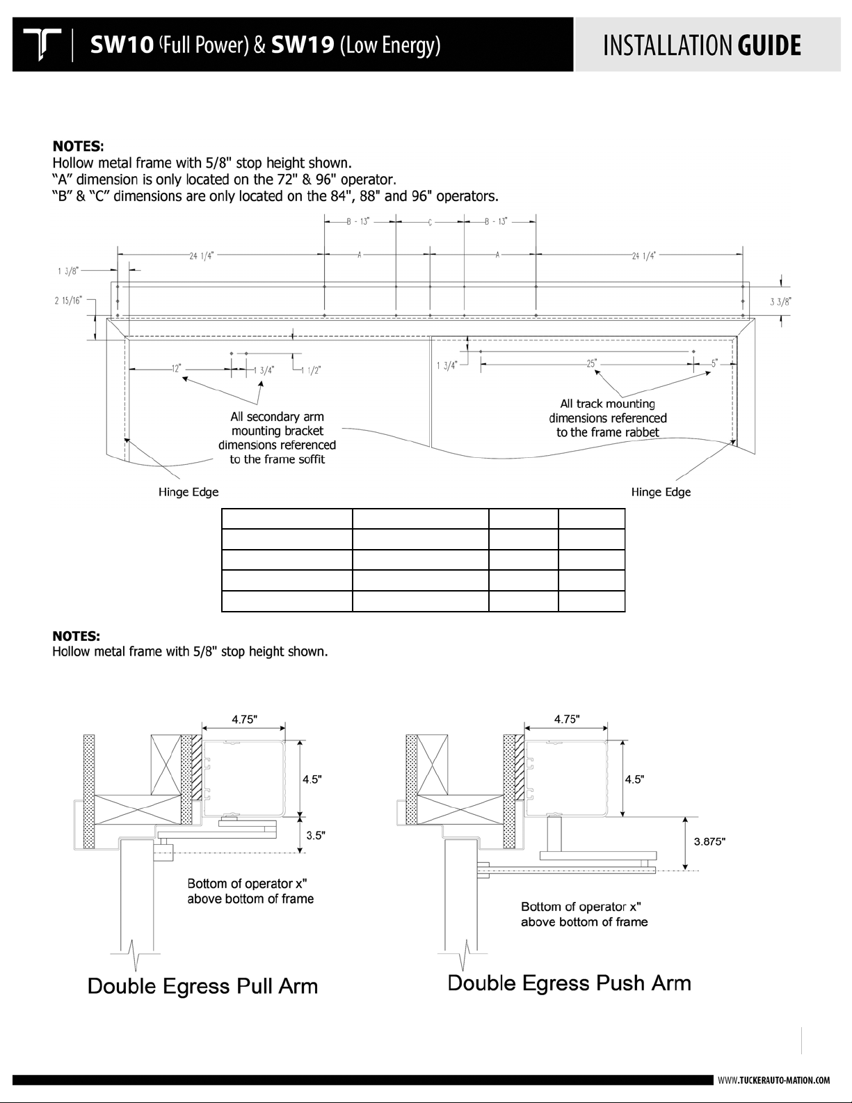
PULL SIDE INSTALLATION DOUBLE
!
!
Page 10
!
920.1020.15
10
Opening Width
Operator Width
A Dim
C Dim 72" 75"
12-7/16"
N/A
84" 87"
N/A
10-7/8" 88" 91"
N/A
14-7/8"
96" 99"
24-7/16"
22-7/8"
!
DOUBLE EGRESS INSTALLATION
!
!
Page 11
!
920.1020.15
11
!
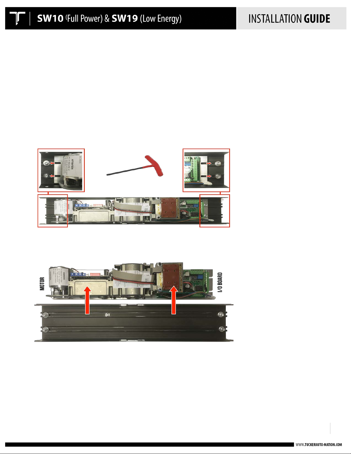
MOUNT THE OPERATOR(S)!!
!
• Operator is non-handed – same operator for all hands of doors
• Handing is determined by how the operator is mounted inside the header
• The operator is mounted to a short aluminum “drive” plate that is held into the header by 5 mounting screws.
Four (4) of the screws secure the drive plate. One (1) screw is used to locate the drive plate using a ‘keyhole’
configuration. The keyhole allows for easy removal of the drive plate without the need to loosen to screw.
Removing the four (4) screws allows the drive plate & operator to be removed from the header and rotated 180
degrees to change from a push to a pull or vice versa.
!
Drive Plate mounted in standard position using four (4) screws to secure. Loosen the screws using an 5 mm allen
wrench and slide each one off of the drive plate.
!
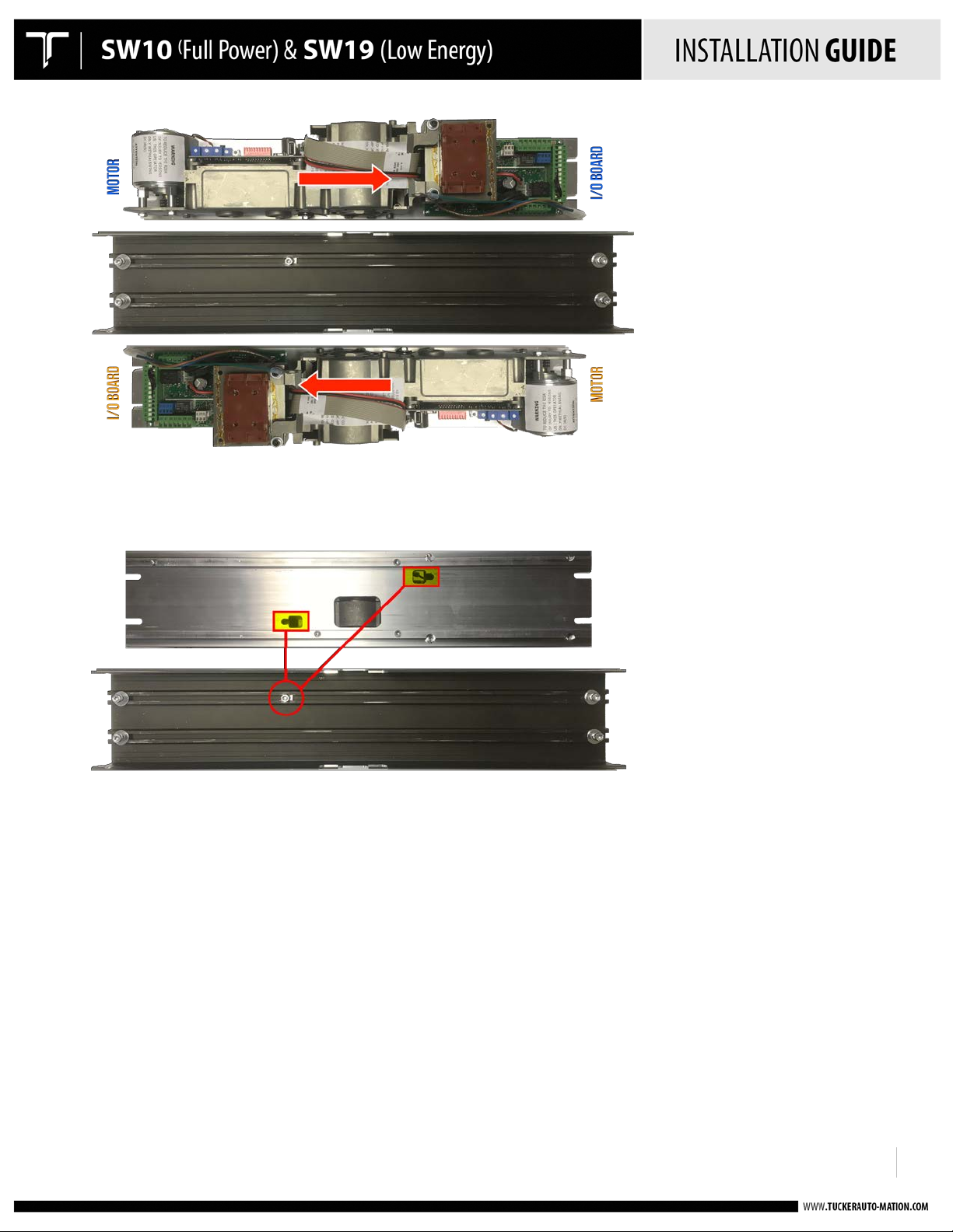
Drive plate removed by shifting to the left and lifting the drive plate off of the locating screw.
!
!
!
!
!
!
!
!
!
Page 12
!
920.1020.15
12
!
!
!
!
Drive plate rotated 180 degrees to reverse the operator handing. Re-align locating screw to key slot, insert drive plate
and shift to the right into position. Re-position the four (4) screws to secure the drive plate.
!
Key slot configuration & location screw mounted in backplate
!
!
!
!
!
!
!
!
!
!
!
!
!
!
!
Page 13
!
920.1020.15
13
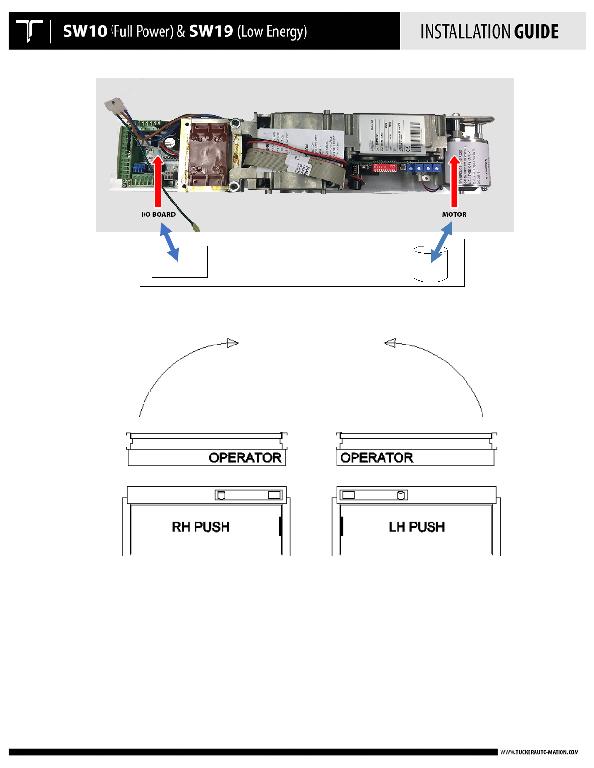
PUSH = I/O BOARD IS TOWARDS THE HINGE JAMB
!
!
!
!
!
!
!
!
!
!
!
!
!
!
!
!
!
!
!
!
!
!
!
!
!
!
!
!
!
!
!
!
!
!
!
!
!
!
!
!
!
!
!
!
!
!
!
!
!
!
Page 14

!
920.1020.15
14
!
!
!
!
!
!
!
!
!
!
!
!
!
!
!
!
!
!
!
!
!
!
!
!
!
!
!
!
• Mount the header to the doorframe with the screws provided.
• The header will overlap the doorframe by 1-1/2" at each side.!
!
!
!
!
Page 15
!
920.1020.15
15
!
!
!
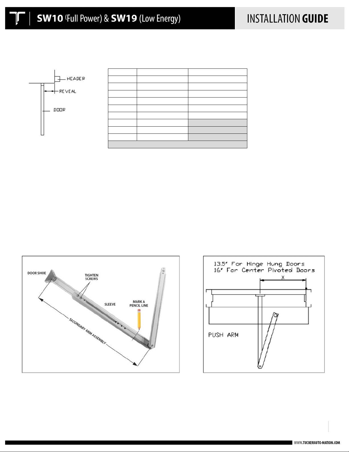
PUSH ARM INSTALLATION
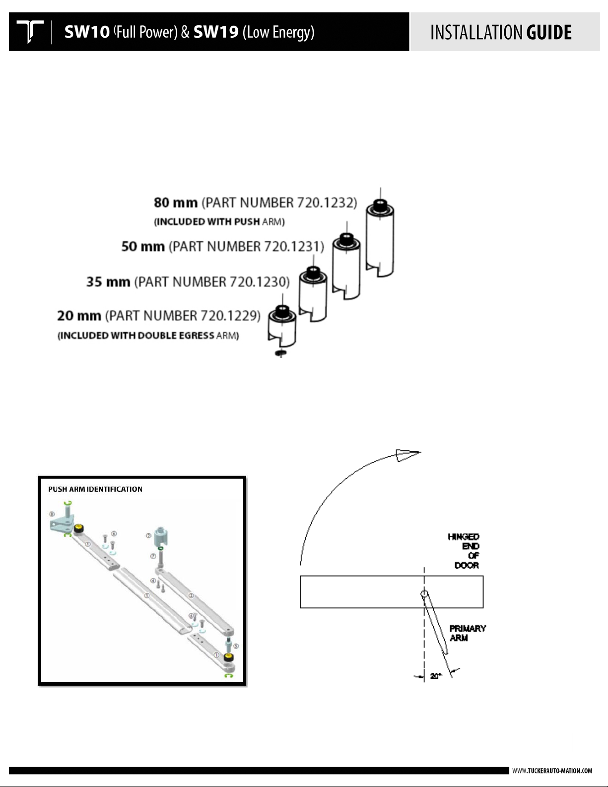
• All push arms come standard with 35mm spindle. 50mm and 80mm available as an accessory.
• Attach the primary door arm approx. 20 degrees past perpendicular and towards the closing direction as shown.
If more spring tension is desired, simply increase the mounting angle to greater than 20 degrees so it results in
increased preload.
!
!
Page 16
!
920.1020.15
16
Reveal
Hinge Hung X Dim.
Center Pivot X Dim.
0
" 13
" 16
"
1
" 14
" 17
"
2
" 15
" 18
"
3
" 16
" 19
"
4
" 17
" 20
"
5
" 18
" 21
"
6
" 19
"
7
" 20
"
8
" 21
"
DEEPER REVEAL
REQUIRES ARM EXTENSION
!
• Adjust the secondary telescopic arm to the prescribed length according to chart:
Before installing
•
insert the secondary and primary arm into the sleeve as it will
Slide
o
o
o
o Mark a
• Attach the secondary arm mounting bracket to the door. The centerline of the bracket should be at 13-1/2” in
from the inside face of the hinge jamb when using butt hinges on the door, and 16” when using a center pivoted
door.
the short arms within the sleeve to obtain the prescribed
Tighten the screws on the short arm that
Double-check
r shoe and the center of the hole
doo
imary
pr
any porti
the
pencil line
arm.
This will
on of the door arm assembly, it is easiest to
be when installed on the door:
is
connected to the door shoe.
"X" dimension of the arm - this is
at the pivot
at the edge of the sleeve where it overlaps
make it easie
r when positioning
the distance between the center of the hole
point of the primary arm (as shown).
the primary arm for
lay
the arm out on a flat
"X" dimension.
the short arm that
final installation.
is
connected to the
surface and
at the
!
!
Page 17
!
920.1020.15
17
Standard Pull Arm
For 0-degree reveal
Use 20mm spindle
Offset (double egress) Pull Arm
For reveal greater than 0 degrees
Use 20mm Spindle
Slide Track
!
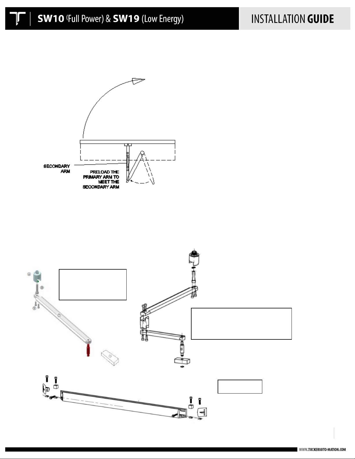
• Rotate the primary arm in the opening direction as to reach the pivot point of the secondary. Attach the arms
together with the hardware provided.
PULL ARM INSTALLATION
!
!
Page 18
!
920.1020.15
18
!
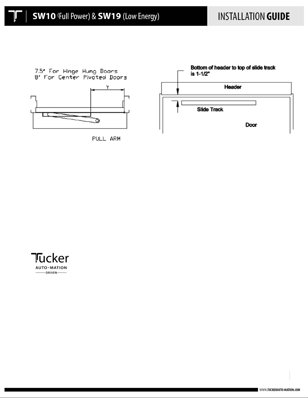
• Install the slide track assembly at the pull side of the door at the proper location from the hinge end of the door
as shown below:
• To install the pull arm, the operator must be powered to the full open position, as it is not possible to install the
arm in the closed position as to allow proper preload.
• Power the door to the open position through the use of the hold-open switch on the side of the header. It may
be necessary to first execute a “setup” on the operator prior to doing this. Refer to the applicable section within
this User’s Guide for proper instruction.
• Once the operator is rotated to the full open position, manually move the door to the desired full open position
and insert the slide track guide block into the track. When completed, the end caps to the track can be installed.
!
!
Page 19

!
920.1020.15
19
BLACK: 115 VAC Power
WHITE: Neutral
GREEN: Ground
WARNING:
Ensure all incoming electrical power is shut off before proceeding with any wiring to
SW10/19. Use only with wire harness provided; failure to do so may result in damage to
equipment or personal harm as well as voiding the warranty.
!
120 VOLT AC ELECTRICAL CONNECTION
!
• Connect the main power to the Black / White / Green connector on the back-plate.
o Main power supply: 120 VAC, 15A, Single Phase, 60 Hz. circuit
o Attach the incoming 120 volt AC line wires to the wiring provided in the header – as
shown below.
• DO NOT TURN POWER ON until all remaining wiring has been completed.
!
!
!
!
!
!
!
!
!
!
!
!
!
!
!
!
Page 20

!
920.1020.15
20
DL1 : GREEN USB CONNECTION
DL2: FLASHING RED LED
DL3: BLUE 5V POWER SUPPLY
DL4: BOARD VALUES DIFFER FROM DIP SWITCHES
(PRESS SW1 MOMENTARILY TO EXTINGUISH YELLOW LED)
!
!
!
POWER ON & INDICATIONS
!
!
!
!
!
!
!
!
!
!
!
!
!
!
!
!
Upon applying power, observe the above LED’s.
NORMAL OPERATION: DL3 will come on steady and then begin flashing after a few seconds.
FAULTY OPERATION; DL2 will be flashing red. This indicates…
• An error condition exists – correct as necessary
• Operator requires setup – launch a setup and proceed accordingly
NOTE: DL4 will illuminate yellow anytime a change has been made to the control, such as a speed or time adjustment.
Momentarily press on SW1 to acknowledge the change and extinguish the yellow LED.
HELPFUL NOTES:
• Speed and time adjustment changes will not take effect until the door closes fully after the adjustment has
been made.
• Hold Open time affects the delay following activation from input 10, 11, and 13.
• When Dip Switch 5 is ON, the blue speed and time potentiometers are disabled and will have no effect.
!
!
!
Page 21

!
920.1020.15
21
!
SET-UP PROCEDURES
• Perform a setup at the control as follows:
o Ensure main power is on
o At the I/O control board, depress the SW1 button for approximately 5 seconds.
When the red LED (LD2) at the Adjustment Board begins flashing rapidly, release
the button. The blue LED will continue flashing.
o Door will slowly go open, recycle partially, close and then re-open.
o Do not interrupt the process and do not move the door manually during this
time.
o If the door does not open and the red LED (DL2) is flashing slowly, check to make
sure the motor is plugged in properly at the control board. Correct as necessary.
o Once the setup process is complete, the door will close and the LED will go out.
o Setup is complete.
IMPORTANT NOTE: If the operator stroke is altered in any way, a re-learn must be
accomplished.
• Upon completion of the Setup, activate the door to open and ensure all performance is
acceptable.
• Adjust opening and closing speed as necessary. If speeds are changed, a re-learn is not
required.
• A re-learn is not required following a main power recovery.
• Adjust hold-open time as required.
• Additional adjustments are available through the TAP.
!
!
Page 22

!
920.1020.15
22
SETUP BUTTON
!
B1 – Battery – use CR1216 battery – required to maintain timer settings and date programmed by the TAP
TR1 – Opening speed adjustment
TR2 – Closing speed adjustment
TR3 – Hold-open time adjustment
TR4 – Closing speed adjustment when power is OFF TR4 will only be enabled when jumper J6 is moved to the correct
pins. (it is enabled by default).
J2 – USB port
J4 – Ribbon cable connector between boards
J5 – Motor Connector
J7 – Power supply connector between boards
SW1 – “Parameter Changed” button
SW2 – 10 Position “Functions” Dip Switch
For adjustments beyond those mentioned herein, use the TAP. See TAP Users Guide for additional information.
!
!
Page 23

!
920.1020.15
23
DS1 NOT USED
DS2
SW2
!
SET THE DIP SWITCHES ON THE I/O BOARD
!
• Set the dip switches according to the application.
• Dip switches are used to apply specific functions to the control.
• There are 3 sets of dip switches. TWO 2 - POSITION on the I/O board (DS1 & DS2), and a 10-
position at the adjustment board (SW2).
!
!
!
!
!
!!!!
!
!
!
!
SET THE DIP SWITCHES ON THE ADJUSTMENT BOARD
!
!
!
• Set the dip switches according to the application.
!
Page 24

!
920.1020.15
24
Description
ON
OFF
1
Closed Door Force
Additional force applied while door is
in closed position. Be sure to maintain
ANSI compliance if using on low
energy application. Cannot exceed 30
lbf to get door moving from jamb.
Disabled (Default)
2
Push / Pull Arm
Slide Arm Application. Operator
stroke at 90° degrees or less. Visible
change in performance may not
always be noticeable.
Push Arm Application.
Operator stroke 90° or
greater. (Default)
3
Night Function (Exit
Only)
Allows activation at input 10 when
On-Off switch is in OFF (night
function) position.
Disabled. The On/Off
switch, when OFF, requires
manual operation of the
door. (Default)
4
Push and Go
Enabled
Disabled (Default)
5
Full Power / Low
Energy
Low Energy performance enabled. 5
seconds to open, 7 seconds hold
open, 5 seconds to close. Speed &
time potentiometers are disabled.
Settings are fixed.
Disabled. Control can be
adjusted for full power or
low energy operation via
potentiometers. (Default)
6
Lockout Function
Overhead presence sensor input (17)
is inhibited during closing cycle unless
input 14 is triggered. Connect COM
and Input 14 to NC output of lockout
safety beam.
Disabled. Overhead
presence sensor input (17)
is inhibited during closing
cycle. Otherwise, if
commanded, it keeps an
open door open and a
closed door closed. A
command at Input 14 will
stall the door. (Default).
7
Inhibit at 30
Degrees Before
Door Fully Open
Input is disabled at 30 degrees prior to
full open door position. Eliminates
need for external inhibiting switch.
Stall function remains uninhibited for full door
stroke. (Default)
8
Power Close
Additional closing force applied for
final 10 degrees of closing.
Disabled (Default)
9
Assisted Manual
Closing***
Enabled assisted closing following a
manual opening
Disabled assisted closing
following a manual opening
10
FACTORY USE ONLY
!
!
!
!
!
*** Tucker Auto-Mation recommends the use of a door-mounted secondary activation device
when dip switch 9 is ON - Enabled.
!
!
Page 25

!
920.1020.15
25
Position
Function
Description
TERMINAL STRIP J5
1
Electric Lock
Relay
Common
2
Electric Lock
Relay
N.O. Dry contact – Contact closes upon activation. May be used for fail-secure locks by
routing 1 leg of power though the relay. Relay is triggered by activation inputs 10, 11, or
16. Relay remains energized until door is fully closed again.
3
Electric Lock
Relay
N.C. Dry Contact - Contact opens upon activation. May be used for fail-safe locks by
routing 1 leg of power though the relay. Relay is triggered by activation inputs 10, 11, or
16. Relay remains energized until door is fully closed again.
4
Door Status Closed
N.O. Contact is closed when door is closed. The contact opens as soon as the door
opens.
5
Door Status –
Common
Common contact for door status
6
Door Status Open
N.C. – Contact is closed when door is open. The contact opens as soon as the door starts
to close. This input can be used for motor connection at lockout relay when power is
looped through, thus switching power on when door is open.
TERMINAL
STRIP J4
7
GND
Common GND
8
GND
Common GND
9
+ 24 VDC
I A. Max Current
10
Internal
Activation
Requires N.O. Contact between input 10 & COM. Remains capable to activate when dip
switch 3 is ON AND On-Off switch is OFF.
11
External
Activation
Requires N.O. Contact between input 11 & COM.
12
Emergency
Closing
Requires N.C. contact between 12 & COM. Upon open contact, door closes and overrides
all other inputs. Remains jumpered if input is not used.
13
Secondary
Activation
Requires N.C. contact between 13 & COM. Disabled in full closed position.
14
“Stall” Safety
Requires N.C. contact between 14 & COM. Upon open contact, (Dip 6 OFF) during
opening, door stops, then resumes at reduced speed when input is released.
15
KEY
KEY IMPUT
16
Alarm Input
N.O. contact, when closed causes door closing. All inputs inhibited during closed contact
(not available on all software versions)
17
Overhead
Presence
Sensor Input
Requires N.O. contact between 14 & +24 VDC (input 9). When input is closed it causes an
open door to stay open and a closed door to stay closed. Works in conjunction with dip
switch #6.
18
GND
Common GND
19
GND
Common GND
20
Aux Relay
Auxiliary Relay NOTE: Relay is triggered by input 14
21
Aux Relay
Auxiliary Relay N.O.
22
Aux Relay
Auxiliary Relay N.C.
23
Alarm Output Common
Common
24
Alarm Output
N.O. output is closed upon closed contact from fire alarm. LED 2 also illuminates.
25
+ 24 VDC
I A. Max Current
26
GND
Common GND
Inputs 27 & 28 not used
!
WIRING CONNECTIONS
!
I/O BOARD CONNECTIONS
(wiring diagrams are located in the Appendix)
!
!
Page 26

!
920.1020.15
26
!
ADJUSTING THE MECHANICAL DOOR STOP
• CAUTION – DO NOT REMOVE THE STOPS
• IMPORTANT - This step may be optional depending on your application
• The mechanical stops are located on the top or bottom of the operator, depending on the
hand of the door.
• Apply 120 VAC Main power to the control
o Place the On-Off-Hold switch to the Hold Open position
!
!
Page 27

!
920.1020.15
27
Door will not open
• Check On-Off switch for proper position
• Check LED status for LD 5, 6, and 7. If any of these LED’s are OFF, the
door will not open. They require a normally closed circuit.
• Launch a new setup – see page 26
• Check status of emergency input 12
• Door has traveled close past the 0 degree position
Door will not close
• Check status of LEDs” LD2, 3, 4, 8 on the I/O board.
• If any of the LED’s are ON, check the associated input
Door will not reach its full open or
closed position
• Check the mechanical stops on the operator for proper adjustment
Slow flashing red LED (LD2) at the
Adjustment Control Board
• Indicates a possible fault in the control.
o Check LED status for the other inputs. This will identify if any
inputs are currently active.
• Indicates a potential faulty setup.
o Loose or incorrect motor connection
o Possible loose chain tensioner - refer to Appendix for chain
tensioner adjustment procedures.
o Launch a new setup. If problem repeats and there are no
other discrepancies noted, replace the operator/control subassembly.
Door closes too fast at last 5 to 10
degrees of closing
• Ensure dip switch 8 is OFF.
• Ensure there is no binding of the door as it is closing through the last
few degrees of closing. If binding exists (from a tight bottom sweep,
for example), correct the condition and then re-launch a new setup.
!
TROUBLESHOOTING
!
!
Page 28

!
920.1020.15
28
!
JOB DOCUMENTATION & CLOSEOUT
• Upon completion of the installation, provide the following to the Owner or their assigned
agent:
o Completed & signed work ticket. Be certain to record any serial numbers for items
that were replaced.
o Completed and signed copy of the AAADM inspection form
o AAADM Owner’s Manual
• Additionally, advise the Owner of the work that was performed and ask if there are any
other doors that may require service.
ACCESSORIES
• Tucker BAT Microwave Motion Sensor - PN: 200.1068
• Tucker TORPEDO ONE door-mounted presence sensor - PN: 200.1087
• Spindle Adaptors 20, 50, 80 mm
• TAP Controller – KP EVO
COMPANY CONTACT
• Tucker Auto-Mation Supply, LLC
Toll Free: 1-855-8 TUCKER (1-855-888-2537) – Service: Tel. 412-823-2537
Email: sales@tuckerauto-mation.com
• WWW.TUCKERAUTO-MATION.COM
!
!
Page 29

!
920.1020.15
29
!
APPENDIX - WIRING DIAGRAMS
LOW ENERGY APPLICATION: PUSH PLATES WITH APPROACH SIDE DOOR-MOUNTED SENSOR
!
!
!
!
!
!
• Non-Swing Side (approach) door-mounted sensor is wired into the secondary activation input (13)
at the SW19 I/O board. It is a normally closed circuit.
• Door-mounted sensor will cause re-activation when in detection during the closing cycle.
• Secondary activation input is disabled at the full closed door position.
• Jumpers must be installed between terminal 8 and 12 & 14 if those inputs are not required for the
application. If they are used for the application, they must be connected to a N.C. circuit.
!
!
Page 30

!
920.1020.15
30
!
SIMULTANEOUS PAIRS
!
!
!
!
!
Page 31

!
920.1020.15
31
!
• When wiring controls for use as a simultaneous pair, all required inputs need to be
sync’d (connected) between Door #1 and Door #2 (shown as dotted lines in above
diagram).
• Example shown above: Push plates are connected to inputs 8, 10 and 11 at door #1
and are connected via sync line to Door #2.
• When using pairs of controls, N.C. inputs 12, 13 and 14 may be sync’d to each other,
OR each control may have it’s own jumpers installed. If any of these inputs are
required for the application, the jumper will be removed for the respective input – in
place of the jumper, a N.C. switching circuit will connected to Door #1, and a sync
line will be connected to Door #2.
• For simultaneous pairs, Tucker Auto-Mation provides a dual harness for the On-Off-
Hold switch. Each plug-in connector for the control is wired in parallel to the On-OffHold switch located in the header end-cap. One switch will control both doors.
• All control adjustments (speed & time delay) must be made independantly at each
control.
• All dipswitches at each control must be set independantly and must match between
controls.
• When using the TAP programmer, settings must be made independantly at each
control and must match between controls.
!
!
!
!
!
!
!
!
!
!
!
!
!
!
!
!
Page 32

!
920.1020.15
32
!
!!!!!!!!!!!!!
APPENDIX - FIRE RATED DOOR APPLICATION
• Perform the installation according to the instructions outlined in this manual.
Additionally, ensure the following conditions have been met:
o When attaching the door arm to the door,
use steel binding posts (Sex Bolts) to attach.
Do NOT use sheet metal screws into the face
of the door. The door arm bracket must be
through-bolted.
o When attaching the header to
the hollow metal door frame,
ensure there are 5 attaching
screws spaced equally apart.
They should be #12 sheet
metal type screws.
!
!
Page 33

!
920.1020.15
33
!
o Fire rated power operated doors must close and latch during a fire alarm condition.
Ensure proper procedures have been followed to allow a main power disconnect
during a fire alarm condition. Always check to ensure compliance to local building
codes.
§ Upon job completion, always perform a functional test to ensure that the
door(s) close and latch following a power loss.
o Other hardware may be required to complete the installation. For example, for pairs
of doors, if an Astragal is installed, a mechanical door coordinator may be required
to ensure a proper coordinated closing during a power loss.
o Only fire rated hardware shall be used on a fire rated door & frame assembly.
o Ensure the Tucker SW10/19 that is being installed has the proper fire rated label
applied to the header.
!
!
Page 34

!
920.1020.15
34
!
!
APPENDIX - TAP PROGRAMMING DEVICE
Please note, some functions of the SW10/19 controller require the use of a hand-held “TAP” programming device.
The following functions require use of this device for programming:
ü Logic Assignment For Inputs
ü Logic Assignment For Outputs
ü Opening & Closing Acceleration
ü Opening & Closing Deceleration
ü Opening & Closing Strength (obstruction force)
ü Opening & Closing Strength Duration (time duration for obstruction force)
ü Night-Time Hold Open Time
ü Delay On Activation (up to 4 seconds)
ü Electric Lock Interfacing
ü Master/Slave Configuration
ü Cycle Count – Maintenance Reset
ü 7-Day Programmable Timer (With Daylight Savings Time)
ü Troubleshooting & Data
!
!
Page 35

KP evo - TAP CONTROLLER
INSTALLATION GUIDE
TUCKER AUTOMATION
KP evo - TAP CONTROLLER
WWW.TUCKERAUTO-MATION.COM
Page 36

KP evo - TAP CONTROLLER
INSTALLATION GUIDE
IMPORTANT
READ THIS SECTION BEFORE PROCEEDING WITH INSTALLATION
Tucker Auto-Mation, LLC (hereafter referred to as “Tucker”) recommends that all of its automated
pedestrian door products beinstalled by a trained automatic door technician and that the resulting
performance of the product be in full compliance with themost current version of the American National
Standards Institute document A156.10 or A156.19 (whichever is applicable) as well as any applicable
building codes and/or re codes. Tucker further recommends that a full inspection of the operating system
be performed in accordance with the guidelines of the American Association of Automatic Door
manufacturers (AAADM). This inspection must be performed by a certied AAADM trained inspector. Tucker
recommends this documented inspection be performed upon completion of the installation as well as,
following the completion of every service call thereafter. If service is not performed within one year of the
previous service action, a routine AAADM inspection should be performed and documented. Under no
circumstance should the product operate for more than one year without an AAADM inspection. Tucker
does NOT recommend installation or service, on any of their automated pedestrian door products, by any
individual who is not certied as an AAADM inspector. Following the installation or service of any Tucker
automated pedestrian door product, if it is deemed unsafe, or is operating in an unsatisfactory manner
according to national performance standards or recommended performance guidelines as dened by
Tucker, repairs should be made immediately. If an immediate repair cannot be made, the product should be
disabled, and appropriate measures should be taken to secure the door in a safe position or to enable the
door to safely be used manually. During this situation, every eort should be made to notify the owner (or
person responsible) of the condition and to advise on corrective actions that must be taken to return the
product to safe operation.
TUCKER AUTOMATION
KP evo - TAP CONTROLLER
920.1003.02 | 01
WWW.TUCKERAUTO-MATION.COM
Page 37

KP evo - TAP CONTROLLER
INSTALLATION GUIDE
TABLE OF CONTENTS
1. KP EVO ........................................ 3
1.1 Installation and connections .................. 3
1.2 Switching on and the home screen ............ 4
1.3 SELECTION menu ............................. 5
1.4 FUNCTIONS menu ............................ 6
2. DIAGNOSTICS ................................. 44
2.1 LEDs check ................................... 44
I/O board LEDs ................................. 44
Logic board LEDs .................................................................................................14
2.2 Inputs and outputs status check .................................................................................14
2.3 Automation status check ........................................................................................ 14
2.4 Warnings ......................................................................................................15
2.5 Errors ..........................................................................................................16
2.6 Other board data ...............................................................................................17
2.7 Firmware versions ..............................................................................................17
2.8 Log Data ....................................................................................................... 17
KP evo TABLES
A P EVO menu ................................................................. 07
B Access permissions and passwords ............................... 13
C I/O board LEDs .............................................................. 14
D Logic board LEDs .......................................................... 14
E Status ........................................................................... 14
F Warnings ...................................................................... 15
G Errors ............................................................................ 16
H Selecting theupload/download function ...................... 18
I Scheduled maintenance ............................................... 21
3. UPLOAD / DOWNLOAD ........................................................................................ 18
4. PUT TING INTO SERVICE ....................................................................................... 19
4.1 Final checks ...................................................................................................19
4.2 Final operations ............................................................................................... 19
Installing a plastic cover ..........................................................................................19
Installing an aluminium cover ................................................................................... 20
5. MAINTENANCE ................................................................................................ 20
5.1 Inserting / replacing the battery ............................................................................... 20
5.2 Replacing the fuse ........................................................................................... 20
5.3 Routine maintenance ......................................................................................... 21
6. INTERCOM .................................................................................................... 22
6.1 Intermode ................................................................................................... 23
6.2 Interlock ..................................................................................................... 23
Interlock with no memory ....................................................................................... 24
Interlock with memory .......................................................................................... 24
6.3 2 Leaves ..................................................................................................... 24
6.4 2 Leav
es + Interlock .......................................................................................... 24
COMPANY ADDRESS............................................................................................
7.
WWW.TUCKERAUTO-MATION.COM
25
920.1003.02 | 02
Page 38

KP evo - TAP CONTROLLER
1. KP evo
1.1 INSTALLATION AND CONNECTIONS
CARRY OUT THE FOLLOWING OPERATIONS WITH THE
ELECTRICITY SUPPLY DISCONNECTED
1. Disassemble the parts (01 ).
2. Break the cable passage insert.
With reference to 02, the KP EVO is designed
for the cables to enter from the back (1) or from
underneath (2).
3. Decide where to position the support and x it
using suitable screws (01 -1).
4. Connect the KP EVO to the 950N2 using a 4 pair
twisted U/UTP AWG24 cable with a maximum
length of 50m (03).
INSTALLATION GUIDE
1
2
02
An optional key device can be connected between ter-
minals G and K in order to enable/disable the KP EVO.
5. Reassemble the parts indicated in (01 ).
1
1
1
max 50 m
U/UTP CAT.5
4x2xAWG24
J3 950N2
03
01
920.1003.02 | 03
WWW.TUCKERAUTO-MATION.COM
Page 39

KP evo - TAP CONTROLLER
1.2 SWITCHING ON AND THE HOME SCREEN
1. Turn power on to the 950N2
2. The display will show the following in sequence:
KP EVO
BOOTLOADER X.X
in which the Bootloader version appears, then
KP EVO
VERSION X.X
in which the rmware version appears, and lastly
A951
xxx dd/mm/yy
xxxxxx
hh:mm
INSTALLATION GUIDE
3. The 4 buttons are used to select controls that,
depending on the screen, appear on the display
above them.
4. By pressing the relative button on the home screen
(04) you can:
- = set the NIGHT mode
- = set the MANUAL mode
- = switch to the FUNCTIONS menu that includes
all the 950N2 conguration parameters.
- = switch to the SELECTION menu that includes
additional operating modes.
By pressing the button to set the NIGHT or MANUAL
mode, the relative icon is highlighted and the description of the operating mode is updated on the display.
Once MANUAL mode has been set by pressing the
relative button, press it again to return to the previous mode.
The content of this home screen, including the xed
icons and those that may appear under certain circumstances, is explained in 04.
current warnings
A951
xxx dd/mm/yy
xxxxxx
timer active
set / deselect NIGHT mode
hh:mm
KP EVO locked
- product name
- day and date or error
- operating mode
- time
switch to the SELECTION menu
switch to the FUNCTIONS menuset / deselect MANUAL mode
04
920.1003.02 | 04
WWW.TUCKERAUTO-MATION.COM
Page 40

KP evo - TAP CONTROLLER
1.3 SELECTION MENU
To access the SELECTION menu from the home screen,
press the button (05).
4 New icons appear on the display that dene the
operating modes that can be set.
The possible combinations can be obtained by pressing the corresponding buttons (05).
After having set the operating mode, press the OK
button to conrm and return to the home screen.
The description of the operating mode on the display
is updated with the description of the one that has
been set.
description of the current operating
mode
INSTALLATION GUIDE
AUTOMATIC
ALWAYS
OPEN
INTERLOCK
(press for 5 s)
%
xxxxxx
BI-DIRECTIONAL
EXIT ONLY
ENTRY ONLY
OK
conrm and return to
the home screen
TOTALLY
100%
OPEN
PARTIAL
%
OPEN
05
920.1003.02 | 05
WWW.TUCKERAUTO-MATION.COM
Page 41

KP evo - TAP CONTROLLER
1.4 FUNCTIONS MENU
To access the FUNCTIONS menu from the home screen,
press the button (06).
The display prompts for a 4-digit password to be
entered.
INSTALLATION GUIDE
1 LANGUAGE
2 PROGRAMMING
The factory-set password is: 0000
- Set the rst digit using the and buttons.
- Conrm using the OK button to move to the next
digit.
- When all 4 digits have been entered, if the pass-
word is correct, access the FUNCTIONS menu as a
USER or a TECHNICIAN.
- Select the item from the menu using the and
buttons.
- Conrm using the OK button to enter.
Press ESC at any time to return to the home screen.
menu items
3 ERRORS
4 WARNINGS
5 CYCLES COUNT
6 DATE/TIME
7 TIMER
8 PASSWORD
8 INFO
menu name
return to the
home screen
ENTER PASSWORD
****
sets the value
conrms the
value
quits without
saving and
returns to the
previous menu
>1 xxxxxxxx
2 xxxxxxxx
3 xxxxxxxx
4 xxxxxxxx
selects an item
from those listed
in the menu
MENU
conrms the
selection
06
920.1003.02 | 06
WWW.TUCKERAUTO-MATION.COM
Page 42

KP evo - TAP CONTROLLER
A KP EVO menu
1 LANGUAGE
1 ITALIANO
2 ENGLISH
3 FRANCAIS
4 DEUTSCH
5 ESPANOL
6 NEDERLANDS
2 PROGRAMMING
1 INPUTS / OUTPUTS
1 INPUTS I1-I8
I1…I8
0 DISABLED
1 EXTERNAL OPEN
4 INTERNAL OPEN
7 AUTOMATIC OPEN
8 SEMIAUTOM. OPEN
10 KEY
11 PARTIAL OPEN
20 CLOSING SAFETY
21 OPENING SAFETY
22 OVERHEAD PRES. SENS
30 EMERGENCY OPEN
31 EMERGENCY OPEN WITH MEM
34 EMERGENCY CLOSE
35 EMERGENCY CLOSE WITH MEM
36 FIRE ALARM
40 ALWAYS OPEN
41 EXIT ONLY
42 ONLY IN
43 NIGHT
44 MANUAL
45 PARTIAL
46 INTERBLOCK ON
2 OUTPUTS O1/O2
60 TIMER
01…O2
0 DISABLED
1 GONG
2 ERROR
4 EMERGENCY ACTIVATE
5 TEST
6 DOOR NOT CLOSED
7 DOOR OPENED
8 DOOR OPENING
9 LIGHT
10 INTRUSION ACTIVE
11 CLOSING SAFETY
12 SAFETIES
NORMALLY OPENED / NORMALLY CLOSED
NORMALLY OPENED / NORMALLY CLOSED
NORMALLY OPENED / NORMALLY CLOSED
NORMALLY OPENED / NORMALLY CLOSED
NORMALLY OPENED / NORMALLY CLOSED
NORMALLY OPENED / NORMALLY CLOSED
NORMALLY OPENED / NORMALLY CLOSED
NORMALLY OPENED / NORMALLY CLOSED
NORMALLY OPENED / NORMALLY CLOSED
NORMALLY OPENED / NORMALLY CLOSED
NORMALLY OPENED / NORMALLY CLOSED
NORMALLY OPENED / NORMALLY CLOSED
NORMALLY OPENED / NORMALLY CLOSED
NORMALLY OPENED / NORMALLY CLOSED
NORMALLY OPENED / NORMALLY CLOSED
NORMALLY OPENED / NORMALLY CLOSED
NORMALLY OPENED / NORMALLY CLOSED
NORMALLY OPENED / NORMALLY CLOSED
NORMALLY OPENED / NORMALLY CLOSED
NORMALLY OPENED / NORMALLY CLOSED
NORMALLY OPENED / NORMALLY CLOSED
NORMALLY OPENED / NORMALLY CLOSED
NORMALLY OPENED / NORMALLY CLOSED
NORMALLY OPENED / NORMALLY CLOSED
NORMALLY OPENED / NORMALLY CLOSED
NORMALLY OPENED / NORMALLY CLOSED
NORMALLY OPENED / NORMALLY CLOSED
NORMALLY OPENED / NORMALLY CLOSED
TIME 1...90 S
NORMALLY OPENED / NORMALLY CLOSED
NORMALLY OPENED / NORMALLY CLOSED
NORMALLY OPENED / NORMALLY CLOSED
INSTALLATION GUIDE
ENABLED / DISABLED
TEST
ENABLED / DISABLED
TEST
NORMALLY OPENED / NORMALLY
CLOSED
3 OP/CLRELAY
NORMALLY OPENED / NORMALLY CLOSED
4 EXTERNAL SELECTOR
POSITION 1…POSITION 2
0 DISABLED
1 NIGHT
2 OPENED
3 EXIT ONLY
4 MANUAL
920.1003.02 | 07
WWW.TUCKERAUTO-MATION.COM
Page 43

KP evo - TAP CONTROLLER
2 MOTION
1 OPENING...2 CLOSING
1...10
SLOWDOWN SPACE 0°...90°
0...10
0.1...3.0 s
1...10
1...10
0...30 s
0...30 s
0...90 s
0...90 s
WITH MEMORY / WITHOUT MEMORY
WITH MEMORY / WITHOUT MEMORY
3 TIMING
4 MOTOR LOCK KIT
ENGLISH
5 INSTALLATION
6 INTERCOM
1 SPEED
2 SLOWDOWN
3 STRENGTH
4 STRENGTH DURATION
5 ACCELERATION
6 DECELERATION
1 PAUSE TIME
2 PAUSE TIME
3 NIGHT PAUSE TIME
4 NIGHT SENSOR NIGHT
1 FUNCTION
2 LOCK DELAY 0...60 tenths of a second
3 RELEASE TYPE
1 ARM TYPE
2 SENSOR TYPE
3 START SETUP ARE YOU SURE ?
4 PUSH AND GO
5 PARTIAL STOP SEC.
6 LEAF DELAY 0°...90°
7 SCP
8 REVERSE STROKE
10 INOUT STATE IN1...IN8 01...02
11 DOOR STATUS
12 OTHER BOARD DATA V_MAIN V_ACC POS I_MOT
1 FUNCTION
2 MASTER/SLAVE NR.
3 INTERCOM REG.
4 NODE LIST
]
DISABLED
NIGHT
EXIT ONLY
NIGHT + MONODIR
ALWAYS
WHEN OPENING
CLOSED
SKID
ARTICULATE
DOOR MOUNTED SYSTEM
OPS AND BEAM
0 DISABLED
1 ENABLED
2 FAST FOOD
DISABLED
ENABLED
DISABLED
ENABLED
DISABLED
ENABLED
DISABLED
INTERMODE
INTERLOCK
2 LEAVES
2 LEAVES + INTERBLOCK
INSTALLATION GUIDE
SLOWDOWN SPEED 1...3
920.1003.02 | 08
WWW.TUCKERAUTO-MATION.COM
Page 44

KP evo - TAP CONTROLLER
7 MISCELLANEOUS
1 DEFAULT DEFAULT
2 BOARD'S DISPLAY
3 INTRUSION
4 KPEVO KEY
5 CONSECUTIVE OBST.
6 TEST ERROR
3 ERRORS
The display shows any current errors
4 WARNINGS
the display shows any current warnings
5 CYCLES COUNT
1 CYCLES NUMBER
ABSOLUTE
RELATIVE
2 MAINTENANCE
MAINTENANCE DATE MAINTENANCE CYCLES
3 CYCLES RESET ARE YOU SURE ? resets the number of cycles
ACTIVATE
NO
STOPPED
NOT BLOCKED
DISABLED
ENABLED
WITHOUT USER PSW
BLOCK
CLOSING
OPENING
DISABLED
ENABLED
DO YOU WANT TO LOAD
0...10
0...10
INSTALLATION GUIDE
DEFAULT CONFIG ?
ENGLISH
6 DATE/TIME
1 SET DATE
2 SET TIME
3 DAYLIGHT SAV TIME
DISABLED
7 TIMER
ENABLED
1 TIMER STATE
DISABLED
ENABLED
2 MONDAY
3 TUESDAY
4 WEDNESDAY
5 THURSDAY
6 FRIDAY
7 SATURDAY
8 SUNDAY
9 MON - SUN
10 MON - FRI
11 JOLLY
12 JOLLY SLOTS
SLOT 1
SLOT 2
SLOT 3
SLOT 4
SLOT 5
SLOT 6
APPLY (appears only if selected LUN - SUN or LUN - FRI)
920.1003.02 | 09
WWW.TUCKERAUTO-MATION.COM
Page 45

KP evo - TAP CONTROLLER
INSTALLATION GUIDE
FUNCTION: 0
FUNCTION: 1
FUNCTION: 2
FUNCTION: 3
FUNCTION: 4
FUNCTION: 5
FUNCTION: 6
FUNCTION: 7
FUNCTION: 8
FUNCTION: 9
FUNCTION: 10
8 PASSWORD
1 TECHNICIAN PSW
CHANGE TEC PSW REINSERT TEC PSW NEW PSW INSERTED
2 USER PSW
CHANGE USER PSW REINSERT USER PSW NEW PSW INSERTED
9 INFO
E950E
E950E
KP EVO
■ PROGRAMMING INPUTS/OUTPUTS
BOOT
APP
APP
VER *.*
VER *.*
VER *.*
NO FUNCTION
AUTO BIDIR TOTAL
AUTO OUT TOTAL
AUTO BIDIR PARTIAL
AUTO OUT PARTIAL
TOTALLY OPEN
PARTIAL OPEN
AUTO IN TOTAL
AUTO IN PARTIAL
NIGHT
PARTIAL
NIGHT
INPUTS
The inputs on terminal board J5 of the I/O board can be congured
with the following functions
Each input can be set to NC or NO according to the
device connected to it.
Disabled
No associated function.
External open
When activated, the door opens and remains open as long as the
input is active. When released, the door waits for the pause time
to elapse and then closes.
This has no eect in the EXIT ONLY or NIGHT modes.
Internal open
When activated, the door opens and remains open as long as the
input is active. When released, the door waits for the pause time
to elapse and then closes.
This has no eect in the ONLY IN or NIGHT modes.
Automatic open
When activated, the door opens and remains open as long as the
input is active. When released, the door waits for the pause time
to elapse and then closes.
Active in the BI-DIRECTIONAL, EXIT ONLY and ONLY IN modes.
This has no eect in the NIGHT mode.
Semiautom. open
When activated:
- if the door is not already open, it opens and remains open
- if the door is already open, it closes
e in the BI-DIRECTIONAL, EXIT ONLY and ONLY IN
Activ
modes.
This has no eect in the NIGHT mode.
BEGINNING
END
hh:mm
hh:mm
Key
When activated, the door opens and remains open as long as the
input is active. When released, the door waits for the night pause
time to elapse and then closes.
Active in the BI-DIRECTIONAL, EXIT ONLY, IN ONLY and NIGHT modes.
Partial open
Only opens the master door when activated in the “2 leaves” mode.
Closing safety
When activated:
- If the door is closing, it reopens
- If the door is already open, it prevents it from closing
- If the door is opening, it has no eect
Opening safety
When activated:
- If the door is opening, it stops until it is released
- If the door is already closed, it prevents it from opening
- If the door is closing, it has no eect
Emergency open
When activated, the door opens (always total) and remains open
as long as the input is active. When released, the door waits for
the night pause time to elapse and then closes.
Also active in NIGHT mode.
Emergency open with memory
When activated, the door opens (always total) and remains open
as long as the input is active. When released, the
open until it is Reset
Emergency close
ctivated, the door closes and remains closed as long as the in-
When a
put is active. When released, the door returns to normal operation.
door remains
920.1003.02 | 10
WWW.TUCKERAUTO-MATION.COM
Page 46

KP evo - TAP CONTROLLER
INSTALLATION GUIDE
Emergency close with memory
When activated, the door closes and remains closed as long as the
input is active. When released, the door remains closed until it
is Reset
Fire alarm
When activated, the door closes, regardless of the operating mode
that has been set, with the lock kept in the released position. It
has priority over any commands that may be active.
Always open
When activated, the ALWAYS OPEN mode is set.
Exit only
When activated, the EXIT ONLY mode is set.
Entry only
When activated, the ONLY IN operating mode is set.
Night
When activated, the NIGHT mode is set.
Manual
When activated, the MANUAL mode is set.
Partial
When activated, the PARTIAL mode is set.
Interblock ON
When activated, the INTERLOCK mode is set.
Timer
When activated, the TIMER mode is set.
OUTPUTS
The outputs on terminal board J5 of the I/O board can be congured
with the following functions
Closing safety
The output is activated when a closing safety device is active.
Safeties
The output is activated when a closing or opening safety device
is engaged.
OP/CL RELAY
Species the logic of the door status relay (NC/NO).
EXTERNAL SELECTOR
Species the operating mode associated with positions 1 and 2 of
the selector on the side of the unit.
■ PROGRAMMING MOTION
OPENING/CLOSING
Speed
Sets the speed of movement.
Deceleration
Species the space (in degrees of rotation of the 950N2 shaft) and
the deceleration speed (on 3 levels) of the door before reaching the
nal open / closed positions.
Strength
Species the maximum crushing force.
Strength duration
Species the maximum thrust time before an obstacle is recognised.
Acceleration
Species how quickly the door reaches the set opening speed when
starting from stop.
Deceleration
Species how quickly the door stops.
Each input can be set to NC or NO according to the
device connected to it.
Disabled
No associated function
Gong
The output is activated and deactivated at 1-second intervals when
the safety devices are engaged.
Error
The output is activated if there is an error.
Emrg. active
The output is activated when an Emergency is triggered.
Test
The output commands a FAILSAFE test on the inputs that are cong-
ured as safety devices on which the option of running a TEST before
movement has been enabled.
Door not closed
The output remains active until the door is closed.
Door open
The output remains active as long as the door is open.
Door opening
The output remains active as long as the door is moving.
Light
The output is activated, fo
door is open in NIGHT mode.
Intrusion active
The output is activated when an intrusion is in progress (i.e. when an
unexpected movement of the door from its closed position is detected).
.
r a programmable length of
time, when the
■ PROGRAMMING TIMING
PAUSE TIME
Denes the pause time of the door when opened by a command,
before closing automatically.
PAUSE TIME P&G
Sets the door pause time when opened by a Push & Go command,
before closing automatically.
Night PAUSE TIME
Sets the door pause time when opened by a command in NIGHT
mode, before closing automatically.
NIGHT SENSOR DELAY
When NIGHTmode is set, the internal detector remains active for the
amount of time set in this parameter, to allow it to be opened only
once. The internal detector is disabled immediately after opening
and in any case upon expiry of the set delay.
■ PROGRAMMING MOTOR BLOCK KIT
FUNCTION
Species the operating mode in which the lock is activated.
LOCK DELAY
Species the opening delay time of the door to allow the lock to be
released, particularly motorised locks.
RELEASE TYPE
Species when power is disconnected from the lock after it has been
mechanically released:
Opening = during the opening phase
Closed = when the door is closed again
920.1003.02 | 11
WWW.TUCKERAUTO-MATION.COM
Page 47

KP evo - TAP CONTROLLER
INSTALLATION GUIDE
■ PROGRAMMING INSTALLATION
ARM TYPE
Species the type of transmission arm installed (shoe or articulated)
START SETUP
Carries out a Setup cycle after conrmation.
PUSH AND GO
Sets the function that commands the automatic opening of the door
after an initial manual push:
Disabled = Push & Go not enabled
Enabled = Push & Go enabled
Fast food = Push & Go enabled in “FAST FOOD“mode (manual
opening, motorised closing)
PARTIAL STOP SEC.
Species the detection area of the safety in opening:
Disabled= obstacle detection active over the entire opening stroke
Enabled= obstacle detection NOT active in proximity to the
opening stop
LEAF DELAY
Species the opening delay between the doors of 2 leaf models.
SCP
Species the function that pushes the door with a greater force in
the nal section of the closure. It is useful to activate this function
if there is high friction, if the seals are particularly rigid or if locks
have a sti latch.
■ PROGRAMMING MISCELLANEOUS
CONFIG. DEFAULT
Shows whether the parameters have been modied, and if so, resets
the factory defaults after conrmation.
BOARD'S DISPLAY
Not active.
INTRUSION
Sets the function in which the door resists attempts to open it
manually.
KPEVO KEY
You can choose between:
Block = the user must enter the user password in order to access
the menus that he is authorised to use.
Without user psw = the user doesn’t need to enter the user
password in order to access the menus that he is authorised to use.
CONSECUTIVE OBST.
Species the maximum number of consecutive obstacle detections
in the same direction of movement, before stopping in an error
condition.
TEST ERROR
Species the eect that the TEST will have when it
detects a safety device fault:
Disabled = the door will remain stationary in an error condition
Enabled= the door will continue to operate at minimum speed
Because activating the SCP function also reduces the
sensitivity of the electronic anti-crushing system
the nal section of closing, DO NOT activate theSCP
function in "low energy" mode.
REVERSE STROKE
Sets the function that makes the door carry out a short reverse stroke
before opening to make it easier to the release the lock.
2 EASY REG.
Registration of BUS 2easy devices.
INOUT STATE
The display indicates the status (on / o) of inputs I1-I8 and outputs
O1-O2 in real-time.
DOOR STATUS
The display indicates the status of the automation in real-time.
OTHER BOARD DATA
The display indicates useful diagnostics information in real-time.
■ PROGRAMMING INTERCOM
FUNCTION
Sets the operating mode.
MASTER/SLAVE NR.
Sets the network ID of the unit.
INTERCOM REG.
Registers the units of the network (to be performed only on the
950N2 with ID1).
NODE LIST
Shows the ID of the units registered (on the master).
in
■ ERRORS
In this menu, the display indicates any current errors that there
may be in real time.
■ WARNINGS
In this menu, the display indicates any current alerts that there
may be in real time.
■ CYCLE COUNTER
The 950N2 has two counters:
- total, non-resettable
- partial, resettable
This menu allows you to view the cycles performed by the automation and reset the partial counter.
It is also possible to set a deadline for scheduled maintenance
according to:
- date (optional)
- number of cycles (from 1000 to 1000000)
Alert 60 will be displayed as soon as one of the two settings (date
or number of cycles) is reached.
Logging in with the user password only allows data
to be viewed.
■ DATE/TIME
This menu allows you to set or modify the date, time and turn
European summer time on / o.
920.1003.02 | 12
WWW.TUCKERAUTO-MATION.COM
Page 48

KP evo - TAP CONTROLLER
To keep the settings even if there is no mains power,
which is necessary for the TIMER to work correctly, a
battery must be installed on the Logic board.
■ TIMER
This menu includes all the parameters for conguring the TIMER
function.
When the TIMER is enabled, the operating mode of the door during
the programmed time bands is set automatically.
A maximum of 6 daily time bands can be dened, and an operating
mode, selected from those available, assigned to each one. Each
time band has a start time and an end time.
The time bands must not overlap.
When the TIMER is enabled, the T icon appears on
the home screen.
To manually change the operating mode set by the
TIMER, it rst has to be disabled.
In order for the TIMER to work correctly, a battery
must be installed on the Logic board.
INSTALLATION GUIDE
■ PASSWORD
This menu allows passwords to be set or modied.
To access the FUNCTIONS menu you are prompted to enter a 4-digit
password.
The 950N2 has two passwords available, with dierent access rights
( B)
In order to quickly program groups of days
time bands, it is possible to simultaneously select all the days of the
week (MON - SUN) and all weekdays (MON - FRI). Once the time
bands that have been dened here have been conrmed using the
APPLY option, they will overwrite any time bands that have already
been programmed for individual days.
If it is necessary to program specic days or periods (e.g. recurring
holidays), you may use the JOLLY function.
A maximum of 6 JOLLY time bands can be specied and an operating
mode, selected from those available, assigned to each one. Each
time band has a start time and an end time.
The time bands must not overlap.
The JOLLY time bands are then assigned to a maximum of 6 INTER-
VALS. An interval can be a single day or a series of days.
If a single day is dened, the start and end date of
the interval must be the same.
The interval must refer to same calendar year
ple: for the period from 25/12 to 06/01, 2 intervals
must be created, from 25/12 to 31/12 and from
01/01 to 06/01).
of the week with the
same
(exam-
B sdrowssap dna snoissimrep sseccA
LANGUAGE
PROGRAMMING
ERRORS
WARNINGS
CYCLES COUNT
DATE/TIME
TIMER
PASSWORD
INFO
TECHNICIAN
PSW
(*)
(*)
USER
PSW
* with restrictions
The user is only allowed to modify the user password.
920.1003.02 | 13
WWW.TUCKERAUTO-MATION.COM
Page 49

KP evo - TAP CONTROLLER
2. DIAGNOSTICS
2.1 LEDS CHECK
I/O BOARD LEDS
Each input on the I/O board, has a LED that indicates
the physical state of the contact:
C I/O board LEDs
LED
DL 1 accessories power on accessories power o
DL 2 - DL9 open contact closed contact
LOGIC BOARD LEDS
There are 4 LEDs on the Logic board:
D Logic board LEDs
INSTALLATION GUIDE
E sutatS
CLOSED
OPENING
OPEN
PAUSE
NIGHT PAUSE
CLOSING
EMERGENCY ACTIVATE
MANUAL
NIGHT
STOP
SECURITIES TEST
ERROR
SETUP in progress
LED
DL 1
green
DL 2
red
DL 3
blue
DL 4
yellow
o
on
ashing
fast ashing
2.2 INPUTS AND OUTPUTS STATUS
The status of each input and output can be checked
via the KP EVO.
Go to menu 2.5.9. The display indicates the status of
the logic as shown in 07. Example:
IN1
= input active
IN1
= input not active
no USB
normal condition
no power or
board failure
boar d parameters the
same as trimmer and DIP
switch values
USB connected
error
/
boar d par amet ers
dierent to
trimmer and
DIP swit ch
values
S etup r e -
quested
normal con-
dition
Button
pressed
§
Setup in pro-
gress
/
/
CHECK
AMOTUA 3.2 TION STATUS CHECK
The current status of the automation system can be
checked via the KP EVO.
Go to menu 2.5.10. The display shows information
regarding the status of the automation.
IN1 IN4
IN5
O1
IN2
IN6
O2
IN3
IN7
IN8
07
920.1003.02 | 14
WWW.TUCKERAUTO-MATION.COM
Page 50

KP evo - TAP CONTROLLER
2. 4 SGNINRAW
Alerts provide information regarding the status or
current phase of the automation and errors that do
not prevent it from operating. It is possible to check
any current alerts via the KP EVO.
Go to menu 4 to view the list of current alerts.
If there is at least one alert, an icon appears on the
home screen.
INSTALLATION GUIDE
F sgninraW
Date and time missing
41
- Reset date/time via the KP EVO
Clock battery discharged or missing
42
Emergency active (including command memory)
44
Timer active
45
Timer function in progress
46
Night mode operation
48
Manual mode operation
49
Partial mode operation
50
Obstacle detected during closure
51
Obstacle detected during opening
52
Number of maintenance cycles on E
53
- Carry out a Reset.
- If the alarm persists, replace the Logic board
Searching for strike on closing
58
Maintenance requested
60
KP EVO fault
61
- Check that the correct device is connected and check the
connections.
- If the alarm persists, update the rmware
- If the alarm persists, replace the Logic board
Intrusion in progress
63
Set-up in progress
65
TEST alarm (only if the “test error” parameter is enabled)
68
- Check the operation of the connected devices
- If the alarm persists, replace the device
- If the alarm persists, replace the Logic board
In this condition, the door moves at a slower speed.
Door opened by a semi-automatic command
69
Slave Intercom mode
71
Intercom alarm
72
- Check the connections
- Check the ID
- If the alarm persists, replace the Logic board
Slave Error / Alarm
73
Interlock alarm
74
- Check the connections
- Check the ID
- If the alarm persists, replace the Logic boar
Non-standard programming
80
2
prom corrupted
d
920.1003.02 | 15
WWW.TUCKERAUTO-MATION.COM
Page 51

KP evo - TAP CONTROLLER
INSTALLATION GUIDE
2.5 SRORRE
Errors are malfunctions that prevent the automation
system from working. They are indicated by a steady
red LED on the Logic board.
After every 5 minutes in which a fault condition
persists and for a maximum of 20 consecutive times,
the 950N2 will perform a Reset to attempt to restore
normal operation so as not to require any action if the
condition that caused the error was temporary. If
the fault persists, remove the cause in order to restore
G srorrE
When an error occurs:
1. Check all the electrical connections
2. Carry out a reset.
3. If the problem persists, carry out the operations described in the table one at a time until the problem is
resolved.
Board failure - Replace the Logic board
01
E2
02
03
04
05
07
09
11
12
15
16
18
19
22
prom failure - Replace the Logic board
Motor driver failure - Replace the Logic board
- Replace the motor
Accessories power supply fault - Check that the accessories power supply is not short circuited
- Check that maximum load of the accessories has not been exceeded
- Replace the Logic board
- Replace the I/O board
Microcontroller error - Reload/update the Logic board rmware
- Replace the Logic board
Motor failure - Replace the motor
- Replace the Logic board
Board voltage anomaly - Replace the Logic board
- Replace the I/O board
Closing safety TEST failed - Check the connections of the safety device
- Check that the safety device is working
- Replace the Logic board
Opening safety TEST failed - Check the connections of the safety device
- Check that the safety device is working
- Replace the Logic board
Setup inhibited - Make sure that Night or Manual mode has not been set.
- Make sure that an Emergency command has not been activated
Encoder fault - Replace the Logic board
Firmware not compatible - Update with the correct rmware
High mechanical friction - Make sure that the leaf has been mounted correctly
remove any fric
- Replace the Logic board
- Replace the gearmotor
Programming data corrupted - Reprogram the board or upload the program les that were saved to the USB
storage device.
- Replace the Logic board
normal operation.
The type of error can be identied via the KP EVO
The error code appears on the home page. Go to
menu 5; the display provides information regarding
the current error.
deriuqer noitcArorrE
and that it moves smoothly,
tion
920.1003.02 | 16
WWW.TUCKERAUTO-MATION.COM
Page 52

KP evo - TAP CONTROLLER
INSTALLATION GUIDE
24
26
27
31
39
Consecutive obstacles in closing - Remove the obstacle in closing.
- Make sure that the leaf has been mounted correctly and that it moves smoothly,
remove any friction
Lock failure - Check the wiring of the lock
- Check that the maximum load of the lock has not been exceeded
- Replace the lock
- Replace the Logic board
Motor rotation fault - Check the polarity of the motor cable
Consecutive obstacles in opening - Remove the obstacle in opening
- Make sure that the leaf has been mounted correctly and that it moves smoothly,
remove any friction
Setup data missing or corrupted - Perform Setup
- Replace the Logic board
O 6.2 THER BOARD DATA
Go to menu 2.5.11 of the KP EVO. The display provides
information on the following parameters:
- V MAIN : input voltage to the Logic board (Volts)
- V ACC : output voltage for accessories (Volts)
- POS : position of the rotating shaft (degrees)
- I MOT : current drawn by motor (Amperes)
2.7 FIRMWARE VERSIONS
Go to menu 9 of the KP EVO to view the rmware
versions of the bootloader, the Logic board and the
KP EVO.
2.8 LOG DATA
The 950N2 records the last 512 system events. A
battery must be installed on the Logic board in order
to save the list of events in memory even if the system
is switched o.
To download the data as a text le, see § .
920.1003.02 | 17
WWW.TUCKERAUTO-MATION.COM
Page 53

KP evo - TAP CONTROLLER
INSTALLATION GUIDE
3. UPLOAD / DOWNLOAD
There is a USB port on the Logic board via which the following operations can be carried out:
- Load data from a USB pen drive (UPLOAD).
- Save data to a USB pen drive (DOWNLOAD).
For both operations, the USB pen drive must be formatted with the FAT or FAT 32 le system.
The NTFS format is not recognised.
In order to upload, the les required, the names of which are indicated in H must be present in the root directory
of the USB pen drive.
1. Turn power o to the 950N2.
2. Insert the USB pen drive in the USB port (J2) on the Logic board.
3. Turn power on to the 950N2.
4. If the device is detected correctly, the green LED DL1 of the Logic (08) board lights up steadily.
5. The available functions are selected by briey pressing button SW1 on the Logic board (08). The
operation to be carried out is indicated by the number of ashes of the green LED. Each time the button
is pressed, the operations selected ar
6. Press and
quickly while the procedure is being carried out. When nished, the result is signalled by the status of
the following LEDs:
- yllufsseccus detelpmoc = ylidaets no )1LD( DEL neerg
- red LED (DL2) on steadily = error
7. Turn power o to the 950N2 and remove the USB pen drive.
hold the SW1 button for at least 3 seconds to use the function. The green LED ashes more
e indicated in H .
J2
H eht gnitceleS upload/download function
Green LED DL1 Function
1 ash
2 ashes
3 ashes
4 ashes
950N2 rmware update
le required: 950N2.hex
KP EVO rmware update, including menu translations
les required: KP EVO.hex e KP EVO_L.bin
950N2 and timer conguration upload
les required:
950N2, timer and LOG data conguration download
les written: 950N2.prg , 950N2.tmr , 950N2.log
110
SW1
DL2
DL1
08
920.1003.02 | 18
WWW.TUCKERAUTO-MATION.COM
Page 54

KP evo - TAP CONTROLLER
INSTALLATION GUIDE
TUP .4 TING INTO SERVICE
4.1 FINAL CHECKS
1. For doors in “low energy” mode, make sure that the forces generated by the leaf are within the limits
permitted by the regulations. Use an impact force tester in accordance with standards EN 12453: 2002
and EN 12445: 2002. For non-EU countries, of there are no specic local regulations, the force must be less
than 67 N.
2. For doors that are not in “low energy” mode, make sure that the test object is detected in all areas covered
by the leaf movement.
4.2 FINAL OPERATIONS
1. Connect the cable of the functions selector at the side of the unit to the I/O board (connector J2).
2. Install the front cover.
3. Highlight all areas with adequate warning signs in which there are still residual risks, even if all possible
safety measures having been adopted. In particular, for doors less than 2 meters high, apply the hazard
warning pictograms in correspondenc
4. Place a “DANGER, AUTOMATICALLY CONTROLLED” sign in a prominent position on the door.
5. Attach the CE marking on the door.
6. Fill out the EC declaration of conformity and the system register.
7. Give the EC Declaration, the system register with the maintenance plan and the instructions for use of the
automation to the system owner/operator.
e with the arm movement area.
INSTALLING A PLASTIC COVER
1. Install the cover xing plates with screws 09-1
on both sides.
2. Partially tighten the screws 09-2.
3. Insert the cover so that the screws t into the slots,
then tighten them.
4. As an alternative to xing it from the side, use the
template to fasten the cover with screws from the
top or bottom (10
5. Press the top and bottom slot covers on (11 ).
1
2
09
10 11
920.1003.02 | 19
WWW.TUCKERAUTO-MATION.COM
Page 55

KP evo - TAP CONTROLLER
INSTALLING AN ALUMINIUM COVER
1. Install the side proles using the screws 12-1
on both sides.
2. Press the aluminium cover on, aligning the slot
with the side on which the transmission arm has
been installed.
5. MAINTENANCE
RISKS
PERSONAL PROTECTIVE EQUIPMENT
INSTALLATION GUIDE
1
1
12
5.1 INSERTING / REPLACING THE
BATTERY
CARRY OUT THE FOLLOWING OPERATIONS WITH THE
ELECTRICITY SUPPLY DISCONNECTED
1. Remove the cover.
2. Install or replace the CR1216 battery on the Logic
board, as shown in 13 .
3. Reinstall the cover.
Always shut o the power supply before performing
any maintenance operations. If the disconnect
switch is not in view, apply a warning sign stating
“WARNING - Maintenance in Progress”. Restore the
power supply only after nishing any maintenance
work and restoring the area to normal.
Maintenance must be performed by the installer or a
maintenance technician.
Follow all safety recommendations and instructions
given in this manual.
Mark o the work site and prohibit access/transit. Do
not leave the work site unattended.
The work area must be kept tidy and cleared after
maintenance has been completed.
Before starting work, wait for any hot components
to cool down.
Do not make any modications to the original
components.
FAAC S.p.A. shall
injury due to components that have been modied
or otherwise tampered with.
bear no liability for damage
or
5.2 REPLACING THE FUSE
CARRY OUT THE FOLLOWING OPERATIONS WITH THE
ELECTRICITY SUPPLY DISCONNECTED
There is a power supply protection fuse on the I/O
board.
To replace it:
1. Remove the cover:
2. Replace the following fuses
- F 4A for the 230 V version
- T 3.15A for the 115 V version
3. Reinstall the cover.
The warranty shall be forfeited in the event of
tampering with components. Only use original
FAAC spare parts.
CR1216
WWW.TUCKERAUTO-MATION.COM
13
920.1003.02 | 20
Page 56

KP evo - TAP CONTROLLER
INSTALLATION GUIDE
5.3 ROUTINE MAINTENANCE
elbaT I lists the operations which must be
performed on a regular basis in order to keep the automation working reliably and safely; these are given
purely as a guideline and should not be considered
exhaustive. The installer/machine manufacturer is
responsible for drawing up the maintenance plan for
the automation, supplementing this list or modifying
the maintenance operations on the basis of the machine characteristics.
I ecnanetniam deludehcS
Operations Frequency/months
Structures
Check the structures and the parts of the building to which the door and the automation is xed: make sure there is no damage,
cracking, breaks or subsidence.
Frame
Check the frame: make sure that it is xed correctly, that it is integral and that there is no deformation or damage. Tighten screws
and bolts where necessary.
Check the hinges: make sure that they are xed correctly, that they are integral, correctly positioned in their seats and that there is
no deformation or damage.
Check the presence
them.
Operator
Check that the cover/casing and all the movable guards are integral and that they are fastened correctly. Tighten screws and
bolts where necessary.
Check the condition of the power cables, the sensor and accessory connection cables and the relative cable glands. 12
General cleaning. 12
Function set-up selector and keyboard
Sensors, protective devices and control devices
If applicable, check that the pictograms that identify the cont
The door
Check that the opening and closing speed is correct. For doors in “low energy” mode, make sure that the opening and closing
times are within the limits permitted by the regulations.
For doors in “low energy”, mode, make sure that it is possible to stop the movement of the door without excessive force (Max. 67N)
at any point along its travel.
Check that the safet
open position when there is an obstacle in the area of movement etc.)
Check the presence, integrity and legibility of the EC marking on the door and the DANGER AUTOMATIC MOVEMENT warning sign. 12
and condition of pictograms that highlight the glass part of the door. If they are missing or damaged, replace
rol devices for disabled persons are present and intact. 12
atsni secived eht lla htiw snoitcerid htob ni ylreporp setarepo rood eht taht kcehC
setarepo rood eht taht kcehC
y system is working correctly (door reverses or stops when an obstacle is detected, that the door stops in the
12
12
21.egamad ro noitamrofed on si ereht taht dna largetni si ti taht :fael eht kcehC
12
21.yrassecen fi ,skcol ro segnih etacirbuL
21.rood eht fo tnemevom fo aera eht fo naelc yllareneG
12
12
21.yltcerroc gnitarepo dna tcatni era yeht taht kcehC
21.yltcerroc gnitarepo dna tcatni era yeht taht kcehC
21.dell
21 .sesion lausunu yna gnikam tuohtiw ylmrofinu dna ylhtooms sevom rood eht taht kcehC
6
6
21.edom gnitarepo yreve ni yltcerroc
6.tneserp fi ,ylreporp gnikrow si kcol eht taht kcehC
6
920.1003.02 | 21
WWW.TUCKERAUTO-MATION.COM
Page 57

KP evo - TAP CONTROLLER
6. INTERCOM
INSTALLATION GUIDE
■ DESCRIPTION
The 950N2 is capable of communicating with
other 950N2 units via an Intercom network connection. This enables the following modes of operation
to be used (KP EVO menu 2.6.1):
- INTERMODE: a master door from which to set the
operating mode for all the other doors that are
connected to the network.
- INTERLOCK: two single doors, where the opening
of one is subject to the closing of the other and
vice versa.
- 2 LEAVES: access consisting of a double leaf.
- 2 LEAVES + INTERLOCK: two interlocked accesses,
each consisting of a double leaf.
Ever y network connected 950N2 should be programmed for the same Intercom mode.
■ CONNECTION
The units in the network are connected via 3 cascade
connected-wires between the J8 connectors of the
I/O boards (14).
The sequence in which the units are wired is unimportant, but it is essential that a CASCADE connection
is used.
The 2 DIP switches on the I/O board must be set as
follows:
- On the rst and last units of the cascade connec-
tion: both ON.
- On intermediate units (if any): both OFF.
■ ADDRESSING
A unique ID (KP EVO menu 2.6.2) must be assigned to
each 950N2 in the network as indicated below.
Do not assign the same ID to more than one unit in
the network.
ON
1
■ REGISTRATION
After having wired up and assigned an address to each
unit, registration (KP EVO menu 2.6.3), must only be
carried out on the 950N2 that has been assigned ID1.
J8
DS2
2
J8
DS2
1
ON
J8
DS2
2
1
ON
CHGCHGCHG
CLCLCL
2
14
920.1003.02 | 22
WWW.TUCKERAUTO-MATION.COM
Page 58

KP evo - TAP CONTROLLER
INSTALLATION GUIDE
6.1 INTERMODE
15 shows the ID to assign to the 950N2 units in
the network.
The system consists of a Master unit and a maximum
of 14 Slave units. The 950N2 Master unit is the only
one on which the operating mode should be set, which
is then also applied immediately to all the Slave units.
With INTERMODE, it is not possible to change the
operating mode of an individual unit.
950N2 The Master must be assigned ID1 and the Slave
units with ID from 2 to 14.
6.2 INTERLOCK
16 shows the ID to assign to the 950N2 units in
the network.
Either of the two units can be designated as the Master
and the other as the Slave. In INTERLOCK mode, one
door can open only if the other is closed. The available
variations are shown below.
If the PARTIAL mode is associated with INTERLOCK,
only the Master leaf opens.
Connect the devices and carry out the programming
and Setup of the individual 950N2 units before
conguring the INTERLOCK using KP EVO.
Select
INTERLOCK.
on the Master unit to activate the
950N2
MASTER
ID=1
950N2
SLAVE
ID=2
950N2
SLAVE
ID=3
950N2
SLAVE
ID=15
15
950N2
Master interlock
ID=1
950N2
Slave interlock
ID=3
16
920.1003.02 | 23
WWW.TUCKERAUTO-MATION.COM
Page 59

KP evo - TAP CONTROLLER
INSTALLATION GUIDE
INTERLOCK WITH NO MEMORY
With 4 sensors: the second opening is not automatic.
In order to open the door, the internal/external sensor
must be
sensor is activated while the door is not yet closed, it
has no eect.
A1 closed
A2 closed
A1 NOT closed
A2 closed
A1 closed
A2 NOT closed
INTERLOCK WITH MEMORY
With 2 sensors or buttons: the second opening is
automatic.
triggered when the other door is closed. If the
EXTERNAL
OPENING
A1
INTERNAL
OPENING
INTERNAL
OPENING
S1 S2 S3 S4
A1 opens A1 opens A2 opens A2 opens
A1 opens A1 opens request
request
opening
A1
request
opening
A1
A2
S3S2
opening
of A2
A2 opens A2 opens
EXTERNAL
OPENING
4S1S
request
opening
of A2
6.3 2 LEAVES
17 shows the ID to assign to the 950N2 units in
the network.
If the two doors overlap, the one that opens rst is
designated as the Master. If there is no overlap, either
of the two units can be designated as the Master and
the other as the Slave.
The movement of the leaves 2 is synchronised.
The internal / external door sensors and safety devices
must be connected to their own unit; all other devices
are connected only to the Master.
Connect the devices and carry out the programming
and Setup of the individual 950N2 units before
activating the 2 LEAF function.
Only use the Master 950N2 to change the operating mode.
The leaf opening / closing delay can be set in menu
2.5.5 of the KP EVO.
2A1A
17
950N2
2 leaves MASTER
ID=1
S2
S1
S3
S4
950N2
2 leaves SLAVE
ID=2
A1
S1 S2
EXTERNAL
OPENING
S1 S2
A1 closed A2 closed A1 opens, then A2A2 opens, then
A1 NOT closed, A2 closed A1 opens and
request opening
of A2
A1 closed, A2 NOT closed request
opening of A1
A2
EXTERNAL
OPENING
A1
request
opening of A2
A2 opens and
request opening
of A1
6.4 2 LEAVES + INTERLOCK
18 shows the ID to assign to the 950N2 units in
the network.
This conguration integrates the 2 LEAVES function (on
two double-leaf accesses) with the interlock function.
Refer to the operating modes described above.
950N2
Master interlock
2 leaves MASTER
ID=1
950N2
2 leaves SLAVE
ID=2
950N2
Slave interlock
2 leaves MASTER
ID=3
950N2
2 leaves SLAVE
ID=4
18
920.1003.02 | 24
WWW.TUCKERAUTO-MATION.COM
Page 60

KP evo - TAP CONTROLLER
INSTALLATION GUIDE
Tucker Auto-Mation, LLC
11075 Parker Dr,
Irwin, PA 15642
Toll Free: 1-855-8 TUCKER
Tel: 412-823-2537
Fax: 412-842-0260
Email: sales@tuckerauto-mation.com
920.1003.02 | 25
WWW.TUCKERAUTO-MATION.COM
 Loading...