

Tucker GTR3, GTR5, GTR4, GTR SERIES, GTR6 Assembly, Installation And Operating Instructions
...Page 1
ASSEMBLY, INSTALLATION AND OPERATING
INSTRUCTIONS
FOR GTR SERIES BARBECUES ON
CABINET TROLLEYS
MODELS:
GTR3, GTR4, GTR5, GTR6.
GTR3 SS, GTR4 SS, GTR5 SS, GTR6 SS.
GTR3 S, GTR4 S, GTR5 S, GTR6 S.
IMPORTANT – PLEASE READ ALL INSTRUCTIONS
BEFORE YOU ASSEMBLE, INSTALL OR
OPERATE THIS APPLIANCE.
Page 2

2
GENERAL WARNINGS
BARBECUE ASSEMBLY INSTRUCTIONS
INSTALLATION INSTRUCTIONS & WARNINGS
SPECIFICATIONS
DIMENSIONS
GAS INSTALLATION AND LEAK TEST PROCEDURE
OPERATING INSTRUCTIONS
COOKING HINTS
TROUBLESHOOTING
SERVICE & MAINTENANCE
WARRANTY
3
4
10
12
13
16
19
20
21
23
24
CONTENTS
Page 3

3
IMPORTANT SAFETY
INSTRUCTIONS
• Tucker GTR Barbecues are approved for
outdoor use only.
• Remove all plastic protection lm from
stainless steel components before assembly.
• Keep this manual for future reference.
• Read all instructions carefully before
assembly and usage of barbecue.
• Clean your barbecue regularly; check the
grease trays for excess grease build up as
damage by grease or fat re is not covered
by warranty.
• Always turn off the gas supply when you
nish barbecuing.
• A canvas cover for this barbecue will extend
its life and ensure trouble free operation.
• Attend an operating barbecue at all times.
• Do not use this appliance indoors or in any
enclosed area.
• Do not spray aerosols in the vicinity of this
appliance while it is in operation.
• Do not place articles on or against this
appliance.
WARNING FOR
YOUR SAFETY
If you smell gas:
1. Shut off gas supply to appliance.
2. Extinguish any open ame.
3. Open lid or hood.
4. If odour continues, immediately call your
gas supplier or your Fire Department.
• Do not use or store ammable materials in or
near this appliance.
• Always leak test /check hose connections
after lling cylinders.
• Check cylinder condition for rust and that
the date stamp is current as every gas
cylinder in Australia must be pressure tested
every ten years.
• Never disconnect the barbecue whilst it is
running.
• Do not modify this appliance in any way.
• Do not allow children to operate the
barbecue.
• If a grease/fat re should arise, turn off the
gas supply immediately until extinguished.
• Always open the Lid or Roasting Hood before
lighting.
HAZARDOUS FIRE OR EXPLOSION MAY
RESULT IF INSTRUCTIONS ARE IGNORED.
It is the consumer’s responsibility to see that the
barbecue is properly assembled, installed and
taken care of. Failure to follow the instructions in
this manual could result in serious bodily injury
and /or property damage.
Page 4
4
BARBECUE ASSEMBLY
INSTRUCTIONS
• Remove the pallet and any plastic lm
protecting or covering any parts of the
Barbecue and Cabinet Trolley before
assembly.
• Cut away any packaging or cable ties that
may be holding components in place.
• Check you have all the correct components
as listed below.
Tools required for assembly – 17mm,10mm
spanner and a Phillips head screwdriver.
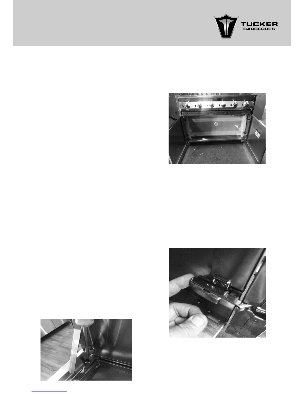
1. If you have chosen a Roasting Hood you
will need to unhinge and remove the Doors
completely from either side of the Cabinet
to allow the removal of the Roasting Hood.
NOTE: The Roasting Hoods are packaged inside
the Cabinet Trolley for transport, they cannot be
removed unless the Doors of the Cabinet Trolley
are removed rst.
• Barbecue body
• Large Flare Guards
• Small Flare Guards
• Plate and grill
• Grease tray
• Hose and regulator
• Cabinet Trolley
• Control Valve adjustment screwdriver
• Check that you have the correct gas type
Barbecue i.e. L.P.GAS (red sticker) NAT GAS
(black sticker). The Gas Type Label is located
on the righthand side of the Barbecue Body.
• GTR BBQs can be installed with either a Flat
Hinged weather cover/ Lid or a Roasting
Hood.
• Make sure to read any separate instructions
on Assembly, Installation and Operation of
the Roasting Hood and / or Wok Burner if
they are to be tted to the BBQ.
• If you have a Flat Hinged Weather Cover/
Lid, attach the Lid onto the back of the BBQ
with the Phillips head bolts provided.
BARBECUE PARTS LIST
2. To remove the Cabinet Trolley Doors simply
push in the spring catches on the back of
each Hinge. This will allow the release of
the hinge from the Hinge Plates that are
attached to the side walls of the Cabinet
Trolley.
Page 5
5
NOTE: Sometimes the Hinges may require a
slight jiggle as they can get stuck.
NOTE: We suggest to do any adjustment of
the Doors after the BBQ is assembled and in
position.
The Castor wheels on the base of the Cabinet
Trolley are also adjustable in height and are to
be used as the primary adjustment for levelling
the cabinet Trolley.
NOTE: Be very careful not to scratch the
Roasting Hood when removing it from within the
Cabinet.
NOTE: Be very careful with the Doors. Do not lay
them down where they might get scratched or
damaged while you are removing the Roasting
Hood.
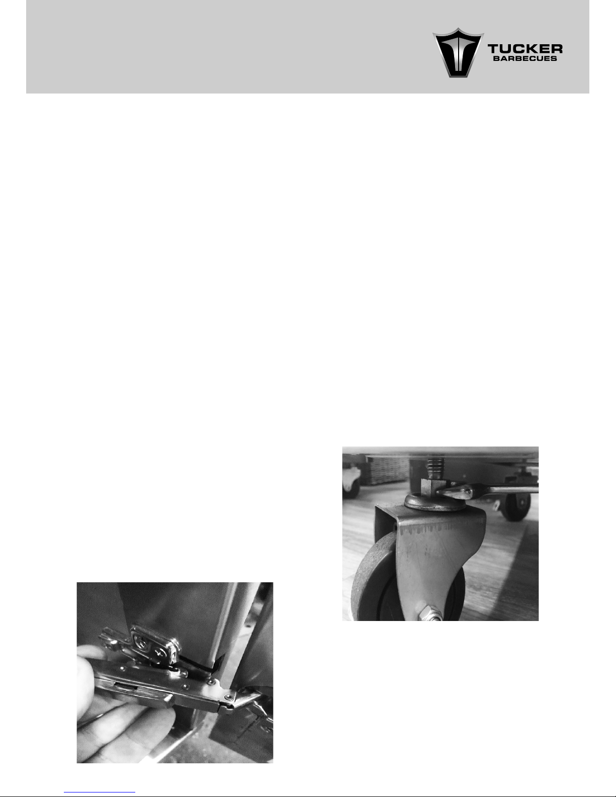
6. To re-attach the Doors back onto the
Cabinet Trolley, simply line up the top
and bottom Hinges on the Doors with the
Hinge Plates tted to the Side Panels of the
Cabinet Trolley. Then simply side them back
into place making sure to latch the Tongue
of the Hinge underneath the Hinge Plate.
You will feel it click into place when it is
attached.
3. As you push in each catch on the back of
the Hinge, just lift the Door away from the
Cabinet to remove it.
4. Now that the Doors are removed, remove
any packaging away from the insides of the
Cabinet Trolley and the ends of the Roasting
Hood. This will allow the Roasting Hood to be
removed from inside of the Cabinet Trolley a
lot easier.
5. Once you have got the Roasting Hood out
of the Cabinet Trolley place it aside and
re-attach the Doors to the Cabinet Trolley.
7. The Door Hinges are adjustable, they can be
adjusted in and out, sideways left and right
as well as up and down, offering you the
ability to ne tune the position of the Doors
once they are tted.
8. It is best to leave the levelling of the Cabinet
Trolley until the very end of the assembly and
installation process to avoid doing it more
than once.
9. To adjust the level of the Cabinet Trolley, use
a 17mm spanner to screw the nut on top of
each of the Castor wheels. You will notice as
you turn the nuts that the Door heights start
to change, when the Doors are level the
Cabinet Trolley should be level as well.
Page 6
6
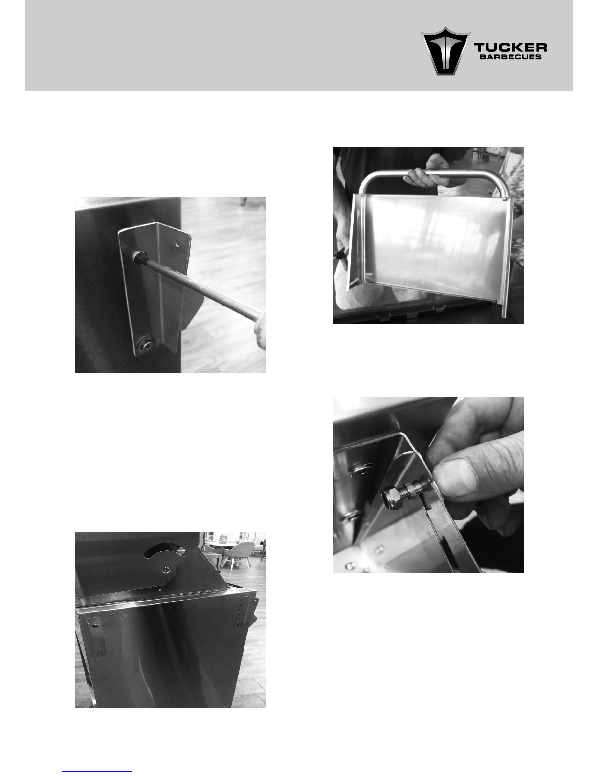
13. Now position the side shelf in between the
two shelf brackets and using the bolt, spacer
and nut, attach the shelf onto the brackets.
10. If you have chosen the optional Side Shelves
for the Cabinet Trolley you will need to rst
t the two shelf brackets supplied with the
shelves onto each side of the BBQ with the
bolts provided.
11. The shelf brackets should mirror each other
on the front and at the back of the BBQ as
per the photo below. The bolts need to be
carefully lined up as they screw into nuts
welded inside the sides of the BBQ Body.
12. Bolt the handles to the end of the side shelf.
NOTE: The holes in the brackets are oversized
and may require a washer to be tted to avoid
the head of the nuts from pulling through the
holes in the brackets.
NOTE: Push the bolt through the hole in the shelf
bracket rst and then through the slot in the
side of the shelf. Now slide the spacer over the
bolt and into the slot in the shelf and tighten the
nut. The spacer allows you to tighten the nut up
rmly yet still allowing the shelf to fold up and
down.
Page 7
7
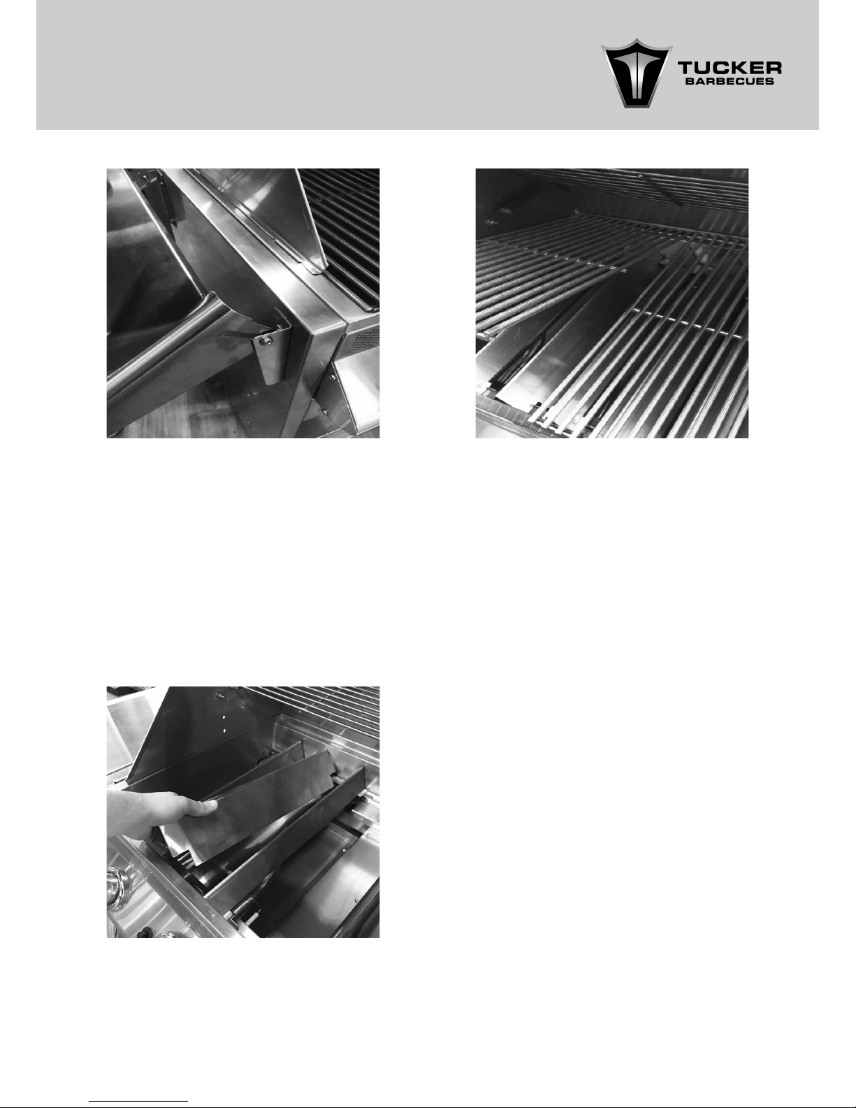
14. Next, place the Flare Guards into position
inside the BBQ.
15. Next place the Cooking Grills into the BBQ
above the Flare Guards and place the Solid
Hot Plate next to them.
16. The Roasting Hood can now be tted.
Remove any packaging, cable ties and
components from inside the Hood. You
should have a Rear Cooking Shelf, Roasting
Rack, Drip Pan and Handle for the Roasting
Hood inside.
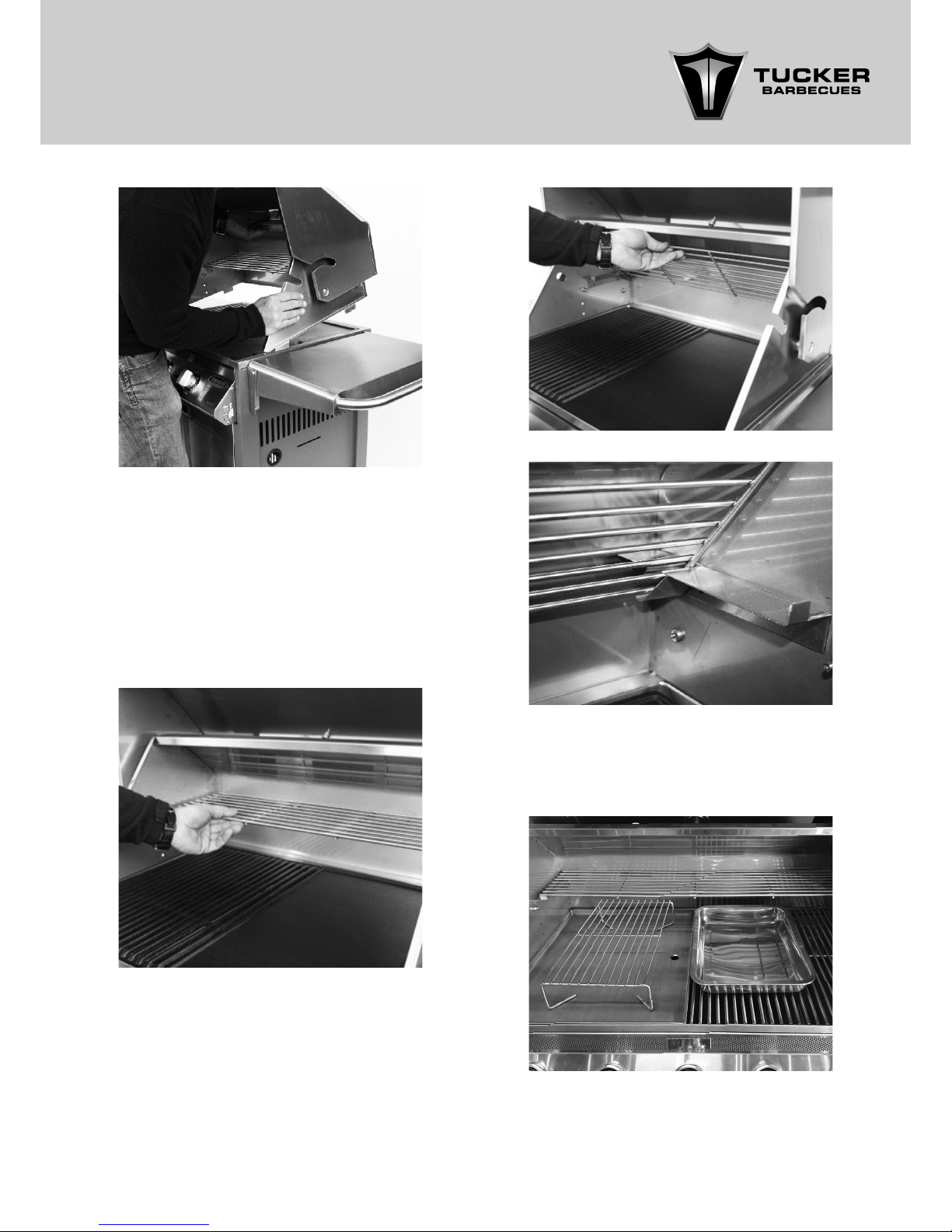
17. First attach the Handle onto the front of the
Roasting Hood with the nuts provided.
18. To t the Roasting Hood onto the BBQ, the
base of the Roasting Hood has 4 x locating
tags that t into corresponding slots on the
top of the BBQ.
19. Slide the angled tags on the front of
the base of the Roasting Hood into the
corresponding slots in the front of the BBQ.
You will need to angle the base of the
Roasting Hood down toward the front of the
BBQ so that it allows the tags to slot into the
BBQ easier.
NOTE: The Flare Guards are only required
beneath the open Cooking Grill section of the
BBQ.
NOTE: The Flare Guards are NOT to be placed
under the Solid Cooking Plate as it will reduce
the ability of the BBQ to heat the Solid Cooking
Plate.
The smaller Flare Guards are to be placed
above each of the Burners that will be sitting
below the Cooking Grills.
The Larger Flare Guards are to be placed in
between each of the smaller Flare Guards.
Page 8
8
20. Once the front tags are located into the
BBQ, the tags on the rear of the Roasting
Hood base will locate straight down into the
corresponding slots on the back of the BBQ
for secure attachment.
21. Now place the Rear Cooking Shelf into the
rear of the Roasting Hood onto the support
brackets.
22. The Roasting Rack and Pan are both used
when Roasting and can be stored away
inside the Cabinet Tolley until required.
NOTE: The Rear Cooking Shelf can be stored
away inside the back of the Roasting Hood if
not required.
Page 9
9
The SS Wok has an optional Solid Hot Plate
available as an accessory, if you have one
it must be placed directly above the SS Wok
Burner allowing an equal air gap either side of
the Burner when it is in use.
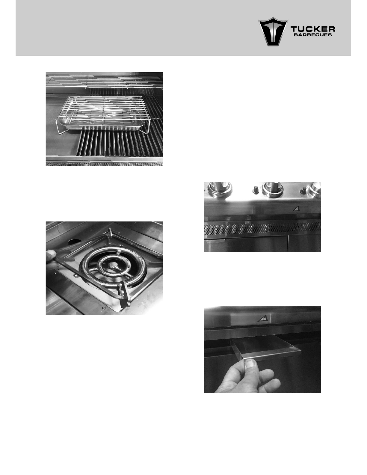
23. If you have a GTR SS or GTR S Model BBQ,
then you will have a Wok Burner integrated
into the Body of the BBQ. Remove any cable
ties securing the Wok Trivet and then place it
back into position above the Wok Burner.
26. The BBQ is now ready for installation.
25. Now check the Grease Tray is free from
packaging cable ties by sliding it in and out.
It is located inside a perforated panel in
the front of the BBQ just above the Cabinet
Trolley Doors.
To access the Grease Tray simply lift-up the
hinged perforated panel from the bottom and
inside you will see the Grease Tray, it should be
located roughly in the middle of the base of the
BBQ.
Pull out the Grease Tray, it should slide in and
out easily between the two locating rails. Make
sure there are no cable ties attached restricting
it from sliding in and out. Slide the Grease Tray
back into position and fold down the hinged
front panel to secure it in place.
24. The SS Wok Burner can be tted with an
optional Hinged Flat Weather Cover/ Lid or a
Roasting Hood to protect it from the weather
when not in use. Read any Assembly,
Installation and Operation Instructions
packaged with the Roasting Hood.
NOTE: The Trivet is used to support either a Wok
or Pot with a diameter of no less than 230mm.
NOTE: The S Wok can only be t/ installed with a
Hinged Flat Weather Cover/ Lid.
WARNING: A Roasting Hood must not be t/
installed above it.
NOTE: A Solid Hot Plate cannot be used above
the S Wok Burner.
Page 10

10
INSTALLATION INSTRUCTIONS
& WARNINGS
INSTALLATION INSTRUCTIONS INSTALLATION WARNINGS
READ THE IMPORTANT INFORMATION
ON THE FRONT OF THE BARBECUE.
This barbecue is designed and approved for
outdoor use only.
Be mindful of the location of the installation of
the barbecue.
If you are using the roasting hood it is better that
the prevailing wind blows into the front of the
BBQ during cooking.
NOTE: Strong winds blowing into the back or
across the back of the hood whilst cooking with
the hood closed can cause overheating of the
BBQ. The Roasting Hood is designed so that Hot
air from inside the Roasting Hood is released
through the vent in the top of the Roasting
Hood when it is shut while roasting.
Strong winds can prevent the hot air escaping
out of this vent and may even in some cases
push the hot air down and out the front of the
base of the BBQ Fascia where the cold fresh air
is designed to enter the BBQ Body.
This choice of installation can cause the front of
the BBQ to get unusually hot and can damage
the ignition system and control valves.
The intended use of this barbecue is to be
installed onto a Tucker GTR Cabinet Trolley.
Be sensible about the location of your
barbecue.
The barbecue must be located on a solid and
level surface that can safely support the BBQ.
The Cabinet Trolley is tted with lockable
Stainless Steel Castors, when you have your BBQ
installed into position, the brakes on the Castors
must be locked to avoid the Cabinet Trolley
from moving during use.
Do not locate the barbecue near combustible
materials or surfaces, either above or around
the barbecue such as overhanging trees,
bushes or ammable liquids and the like.
Do not obstruct any of the air ventilation
openings on the front of the barbecue.
Do not use this appliance indoors or on marine
craft.
This appliance shall only be used in an above
ground, open-air situation with natural
ventilation, without stagnant areas where
gas leakage and products of combustion
are rapidly dispersed by wind and natural
convection.
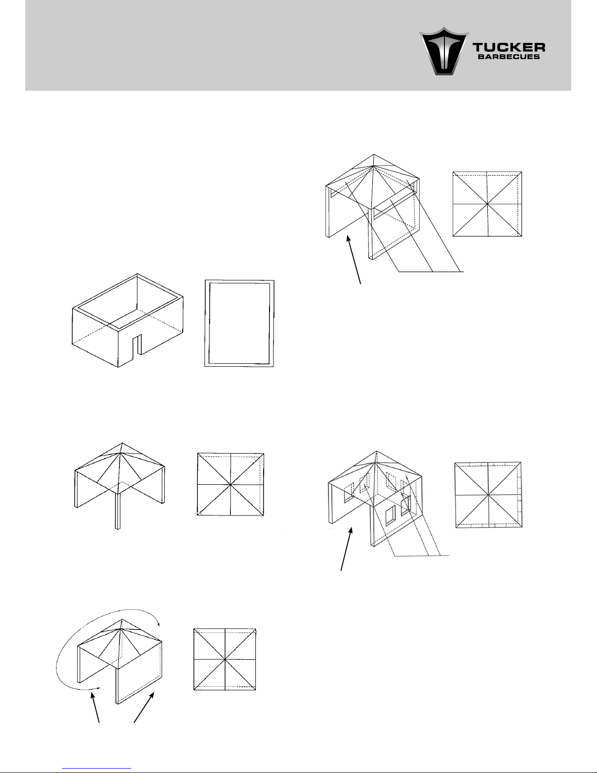
Any enclosure in which the appliance is used
shall comply with one of the following:
• An enclosure with walls on all sides, but at
least one permanent opening at ground
level and no overhead cover. (gure 1)
• Within a partial enclosure that includes an
overhead enclosure and no more than two
walls. (gure 2 and 3)
• Within a partial enclosure that includes an
overhead cover and more than two walls,
the following shall apply. (gures 4 and 5)
• At least 25% of the total wall area is completely open.
• At least 30% of the remaining wall area is
open and unrestricted.
• In the case of balconies, at least 20% of the
total of the side, back and front wall areas
shall be and remain open and unrestricted.
Page 11
11
DIAGRAMMATICAL REPRESENTATIONS OF
OUTDOOR AREAS
FIGURE F1 – OUTDOOR AREA – EXAMPLE 1
FIGURE 4 OUTDOOR AREA –EXAMPLE 4
FIGURE F2 – OUTDOOR AREA – EXAMPLE 2 FIGURE F5 – OUTDOOR AREA – EXAMPLE 5
FIGURE F3 – OUTDOOR AREA – EXAMPLE 3
The following gures are diagrammatical
representations of outdoor areas. The areas
used in the gures below are examples – the
same principles apply to any other shaped
area.
Both ends open
Open side at least
25% of total wall area
30% or more in total
of the remaining wall
area is open and
unrestricted.
OPEN AT SIDE AT LEAST 25% OF TOTAL WALL AREA. 30% OR
MORE IN TOTAL OF THE REMAINING WALL AREA IS OPEN
AND UNRESTRICTED
OPEN SIDE AT LEAST 25% OF TOTAL WALL AREA. 30% OR
MORE IN TOTAL OF THE REMAINING WALL AREA IS OPEN
AND UNRESTRICTED.
Open side at least
25% of total wall area
30% or more in total
of the remaining wall
area is open and
unrestricted.
Page 12
12
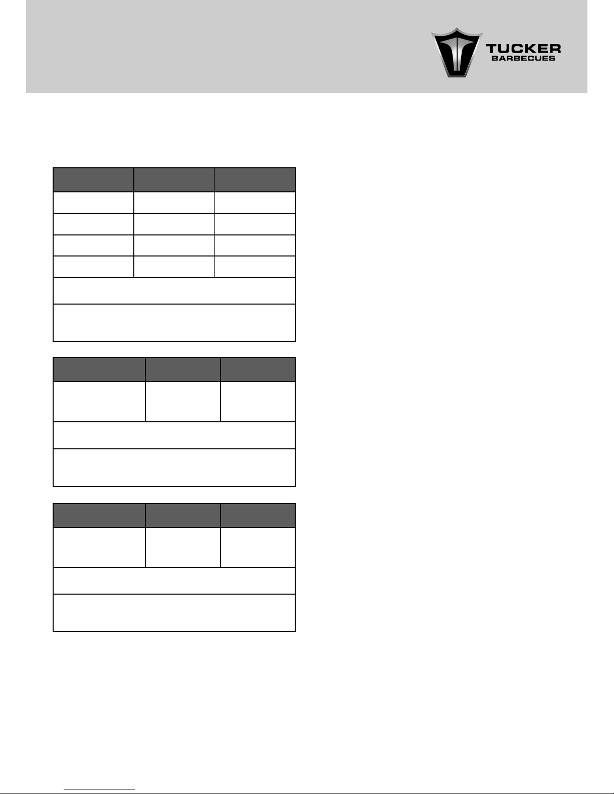
BARBECUE GAS CONSUMPTION
TUCKER GTR BARBECUES ARE MADE AND
APPROVED TO AUSTRALIAN STANDARDS
A.G.A. APPROVAL NO. AGA 8236-G
SPECIFICATIONS
(In Mega Joules Per Hour)
Model Natural Gas LPG:
GTR3 39mj 40.5mj
GTR4 52mj 54mj
GTR5 65mj 67.5mj
GTR6 78mj 81mj
Natural Gas injector size 1.7mm Pressure 1KPA
Propane Gas injector size 1 mm Pressure
2.75 KPA
Model Natural Gas LPG:
Integrated
S Wok/ST Wok
12.5mj 15mj
Natural Gas injector size 1.8mm Pressure 1KPA
Propane Gas injector size 1.1 mm Pressure
2.75 KPA
Model Natural Gas LPG:
Integrated SS
Wok
17mj 18mj
Natural Gas injector size 1.9mm Pressure 1KPA
Propane Gas injector size 1.1 mm Pressure
2.75 KPA
For LP Gas connections, an approved 2.75 KPA
regulator and hose assembly connection to the
appliance is tted by the manufacturer.
The appliance inlet is 3/8 S.A.E. male and
is located in the base of the BBQ, on the
righthand side at the front.
The minimum capacity propane cylinder for this
barbecue is 4 KG.
Warning in freezing conditions the pressure of
Propane gas can be reduced in the Cylinder
Tank causing a lack of gas pressure, this may
affect the way the barbecue operates.
The intended use of this barbecue is to be
installed into a Tucker GTR Cabinet Trolley,
Pedestal Trolley, Chef Stand or into a Tucker
Zero Clearance Insulation Jacket.
Alternatively, it may be set into brickwork.
Be sensible about the location of your
barbecue.
The barbecue must be located on rm and
level ground.
Do not locate the barbecue near combustible
materials or surfaces, either above or around
the barbecue.
Do not obstruct any of the air ventilation
openings on the front of the barbecue.
Page 13
13
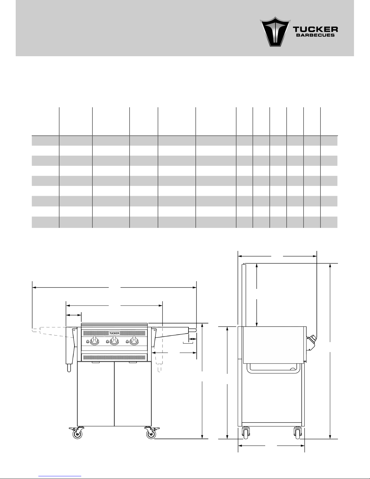
DIMENSIONS OF GTR BARBECUES WITH A
FLAT LID INSTALLED ON CABINET TROLLEY
(Measurements are in mm)
DIMENSIONS
Model
Width with
shelf open
(A)
Width with
shelf closed
(B)
Depth
(C)
Height with
Lid Open
(D)
Height with
Lid Closed
(E)
(F) (G) (H) (I) (J) (K)
GTR SS 1205 665 635 1440 935 370 70 100 540 900 550
GTR3 1340 800 635 1440 935 370 70 100 540 900 550
GTR3SS 1760 1220 635 1440 935 370 70 100 540 900 550
GTR4 1500 960 635 1440 935 370 70 100 540 900 550
GTR4SS 1920 1380 635 1440 935 370 70 100 540 900 550
GTR5 1660 1120 635 1440 935 370 70 100 540 900 550
GTR5SS 2080 1540 635 1440 935 370 70 100 540 900 550
GTR6 1820 1280 635 1440 935 370 70 100 540 900 550
GTR6SS 2240 1700 635 1440 935 370 70 100 540 900 550
A
B
F
E
C
I
D
J
K
H
G
Page 14
14
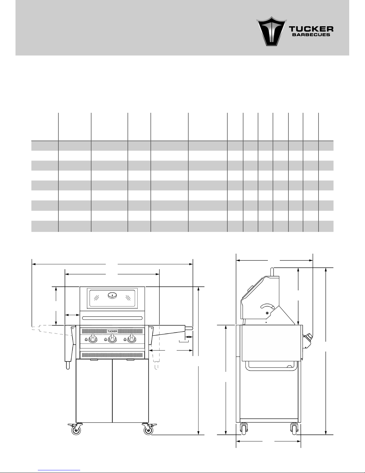
DIMENSIONS OF GTR BARBECUES WITH
ROASTING HOODS INSTALLED ON CABINET
TROLLEYS
(Measurements are in mm)
Model
Width with
shelf open
(A)
Width with
shelf closed
(B)
Depth
(C)
Height with
Hood Open
(D)
Height with
Hood Closed
(E)
(F) (G) (H) (I) (J) (K) (L)
GTR SS 1205 665 635 1370 1220 370 70 100 320 470 900 550
GTR3 1340 800 635 1370 1220 370 70 100 320 470 900 550
GTR3SS 1760 1220 635 1370 1220 370 70 100 320 470 900 550
GTR4 1500 960 635 1370 1220 370 70 100 320 470 900 550
GTR4SS 1920 1380 635 1370 1220 370 70 100 320 470 900 550
GTR5 1660 1120 635 1370 1220 370 70 100 320 470 900 550
GTR5SS 2080 1540 635 1370 1220 370 70 100 320 470 900 550
GTR6 1820 1280 635 1370 1220 370 70 100 320 470 900 550
GTR6SS 2240 1700 635 1370 1220 370 70 100 320 470 900 550
A
B
E
K
L
C
J
D
F
I
H
G
Page 15

15
NOTE: The manifold inlet is in the base of the
BBQ at the front on the right-hand side. Manifold
diameter is 20mm square tube.
The GTR Roasting Hood if tted is 320mm high
from the top of the Cooking Surface when shut
and 410mm high when open.
The back of the GTR Roasting Hood is ush with
the back of the BBQ when open and does
protrude past the back of the Cabinet Trolley at
all when opening or shutting.
The optional Flat Lid/ Weather Cover is 35mm
high shut and 580mm high open from the
Cooking Surface of the BBQ.
Minimum Side Clearance Allow 200mm
Minimum Rear Clearance Allow 200mm
Rear Wall 100mm
Side Walls 100mm
Above BBQ with out Roasting Hood 800mm
Above BBQ from top of Roasting Hood 800mm
MINIMUM CLEARANCES SURROUNDING BBQ
BODY TO COMBUSTIBLE MATERIALS ARE AS
FOLLOWS
MINIMUM CLEARANCES ABOVE COOKING
SURFACE OF BBQ TO COMBUSTIBLE WALLS
If the BBQ is installed into a tucker GTR zero
clearance cabinet trolley the clearances to
combustibles are zero at the rear and either side
of the BBQ body.
NOTE: The wall surfaces above the BBQ cooking
surface at the rear and on either side of the BBQ
must be non-combustible material otherwise
a clearance of 100mm to combustibles is
required.
Page 16
16
CONNECTION OF A GAS CYLINDER TO
THE BARBECUE IS AS FOLLOWS
The hose assembly connection to the appliance
is tted by the manufacturer.
WARNING: there must be no naked ames in
the area when connecting the barbecue to a
gas supply.
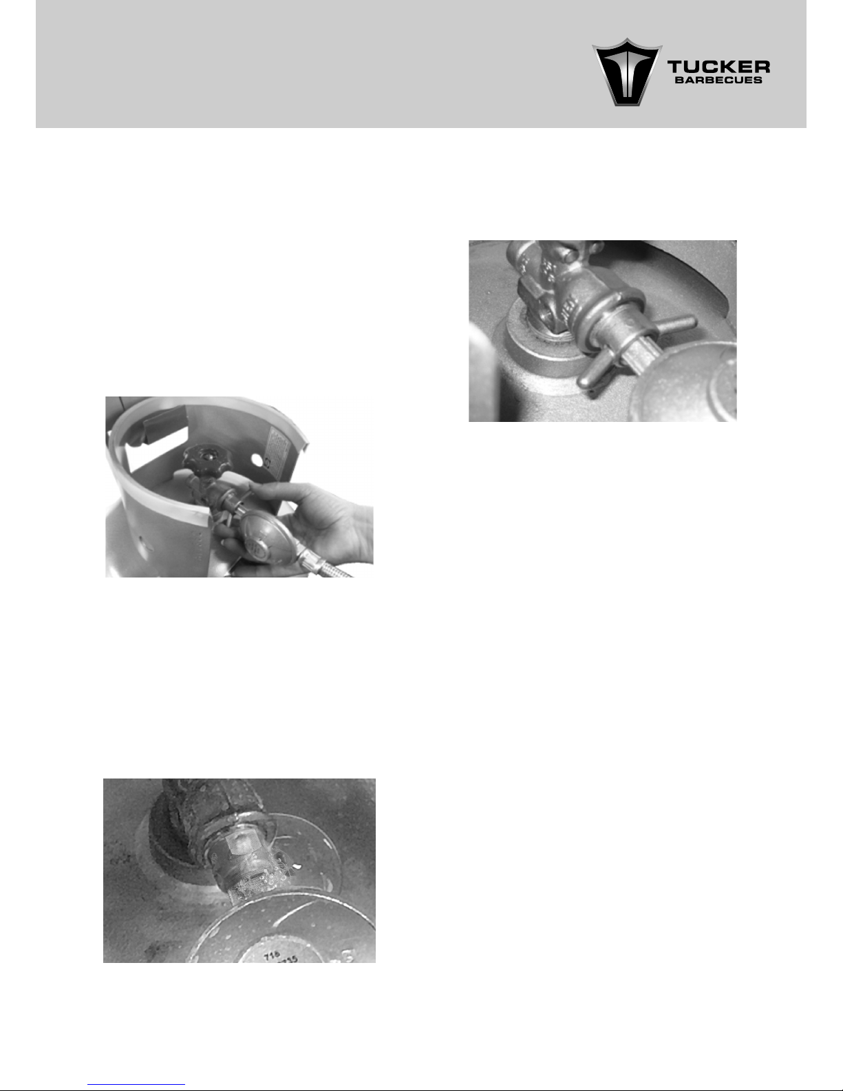
• Attach the regulator to the gas cylinder by
tightening the wing nut on the regulator rmly by hand.
• Once connected, leak test the connections
by brushing a solution of soapy water around
the joints and gas cylinder valve.
NOTE: You must have the control knobs in the
off position and have the gas supply on at the
cylinder valve to test for leaks.
Photo of what a typical leak looks like.
If bubbles appear around the connections,
you have a leak.
GAS INSTALLATION AND
LEAK TEST PROCEDURE
Turn off the gas supply and tighten or re-seal
the connection.
Leak test the connections again
Photo of what a good connection looks like
i.e. no bubbles.
If leaks are still present do not use the barbecue,
contact the place of purchase or your local
dealer.
The GTR Cabinet Trolley has been designed
so as the Gas Cylinder can be stored securely
inside the Cabinet. There is a securing chain attached inside the right hand Cabinet Doors and
a manual lighting match holder is also attached
to the chain.
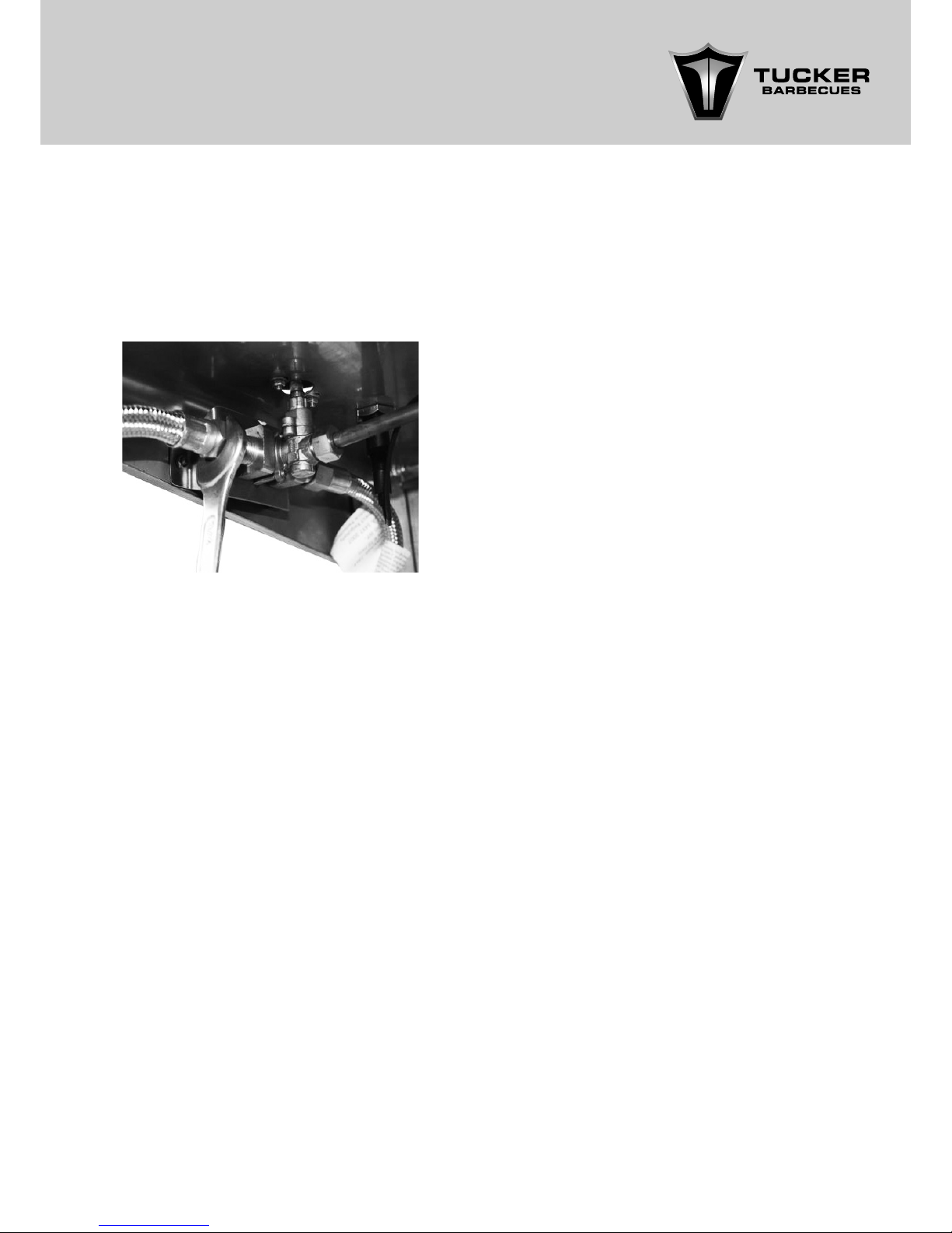
For the attachment of an S Wok Side Shelf you
must rst turn off the gas supply. Remove the
existing trolley side shelf and then disconnect
the existing hose and regulator attached to the
BBQ Gas Inlet.
Now re-connect the hose and regulator to the
Gas Inlet on the right-hand side of the Wok
burner Manifold.
The Short Wok Hose supplied with the Wok must
be connected to the outlet on the left hand
side of the Wok Burner Manifold and the other
end of the Hose must be connected to the BBQ
Gas Inlet.
The hose connections must be connected rmly
with a spanner.
OPTIONAL GTR S SIDE SHELF WOK BURNER
INSTALLATION.
Page 17
17
Check that the hose is not kinked or under
tension.
Apart from the connection point the hose must
not be touching any part of the barbecue
or Wok burner where it may get hot and be
damaged.
Check that the hose is not kinked or under
tension.
Apart from the connection point the hose must
not be touching any part of the Barbecue
or Wok burner where it may get hot and be
damaged.
For storage, cylinder exchange or relling,
disconnect the hose at the cylinder only.
Do not disconnect the hose from the appliance.
Do not attempt to open or adjust the regulator,
if you think it is not working properly consult your
local dealer.
FOR PERMANENT CONNECTIONS to natural
gas or a xed propane supply, an authorised
person, in accordance with these instructions,
local gas tting regulations, municipal building
codes, the AGA installation code AS5601 and
any other relevant statutory regulations, must be
employed.
NOTE: The installer must test the BBQ when the
installation is completed. Before leaving the
installer must make sure the appliance operates
correctly and is safe for the operator to use.
The gas inlet connection must have a thread in
accordance with AS ISO 7.1 or AS 1722.2.
For connection to a natural gas bayonet tting,
a gas regulator must be tted at the inlet of
the appliance, and an approved 10mm, class
A, natural gas hose (no longer than 2 metres),
going from the gas regulator to the bayonet
point, complying with AS1869 must be used.
Where a mobile appliance is to be connected
to a xed gas supply via a exible hose
connection the restraining cord supplied must
be xed to the appliance and the wall/oor
within 50mm of each connection point. The
length of the restraining cord shall not exceed
80% of the length of the hose as it is designed to
prevent stress on the hose assembly when the
appliance is moved out of its normal operating
position.
It is recommended that an isolation valve and
union be tted before the barbecue; refer
AS5601/ AG601 for correct pipe sizing to ensure
adequate gas is supplied to the appliance.
For natural gas check the pressure of the
regulator and adjust it if necessary to the
pressure shown on the data plate.
NOTE: Check for leaks after each gas rell.
GTR S Side Shelf Wok Inlet and Outlet Manifold
Connection.
GAS INSTALLATION
Page 18
18
PROPANE GAS TO NATURAL GAS
CONVERSION PROCEDURE FOR
AUTHORIZED INSTALLER
For alternative types of installation, contact your
nearest dealer.
• Disconnect the gas supply and remove the
plate, grills, are guards and burners from the
barbecue and the Wok burner if tted.
• Remove the main injectors and replace
them with the correct 1.7mm injectors for
each main burner. If a Wok burner is tted
replace the Wok injector with the correct
size required for Natural Gas written on the
data plate.
• Re-assemble the burners, are guards, plate
and grills.
• Replace the PROPANE GAS hose and
regulator with an approved natural gas
regulator and hose.
• Turn the gas on and test for leaks, repair if
necessary.
• Light 3 burners and turn them to high and set
the pressure at 1 KPA.
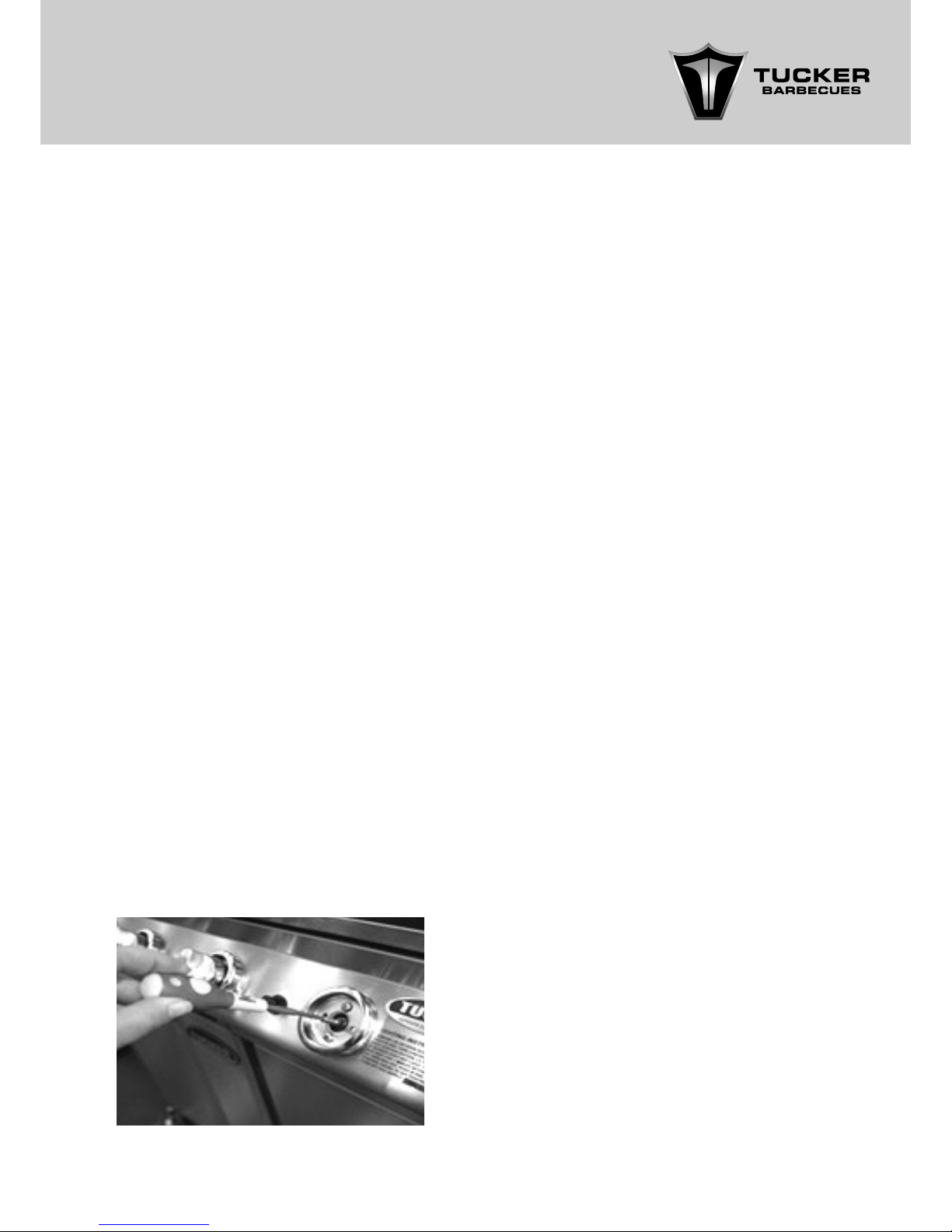
• Now turn all the burners to the “LOW” setting
and check the ame pattern is steady, if
necessary you can adjust the low setting by
removing the gas control knobs and insert
the 2.4mm slotted screw driver supplied into
the valve shaft, the “low” setting can be
adjusted up or down to suit your gas pressure
by turning the screw driver.
• Turn the screw driver anti-clockwise to adjust
the ame height up or turn it clockwise to
Turn it down.
NOTE: you want to achieve the lowest ame
height at “LOW” but you don’t want to
adjust it too low as it could blow out on its
own or due to a breeze.
• Check the operation of the ignition to the
burners and make any necessary adjustment. Note Natural gas is lighter than air you
may need to adjust the ignition probe up a
little higher for it to light.
• Ensure the data plate is changed / altered
to contain correct information i.e. remove
the old Gas type label and replace it with a
natural gas label and date of conversion.
Page 19

19
OPERATING INSTRUCTIONS
GTR BARBECUE LIGHTING INSTRUCTIONS
FOR BBQ AND WOK.
NOTE:
MANUAL LIGHTING INSTRUCTIONS.
NEW BBQ ‘BURNING IN’ PROCESS
PRE-HEATING THE BBQ BEFORE COOKING
1. The Main BBQ Burners will cross light off each
other.
2. Once one Burner has lit, Turn the Control
Knob of the Burner next to it onto the High
position.
3. The ame will jump across to that Burner.
4. If the Burner does not light within 10 seconds,
turn the Burner off and wait 1 minute and
repeat the procedure.
5. Light only one Burner at a time in this
manner.
To light the BBQ manually place a match into
the manual lighting Match Holder located inside
the Cabinet Trolley, attached to the end of the
chain securing the Gas Cylinder.
Before each use remove any accumulated
grease and other cooking residue.
1. Turn on one Control Knob of a Burner under
the Cooking Grill section of the BBQ to High
and light the match in the Match Holder.
2. Push the Match Holder through the gap in
the Cooking Grill in line with the Burner you
have turned on and just below the side of
the Flare Guard. If the BBQ does not light
within 5 seconds turn the Control Knob to off,
remove the Grease Tray to allow built up gas
to disperse, wait 1 minute and try it again.
WARNING: If the Barbecue Burner should not
light after 10 seconds or go out due to strong
winds, care should be taken.
Remove the Barbecue Grease Tray and wait
1 minute before trying to re-light the BBQ to let
any gas that may have built up to disperse.
IMPORTANT: Do not force the Control Knobs,
they will turn easily, depress the Knob and turn it
anti-clockwise.
The Gas Control Knobs can be adjusted from
high to low.
To turn the Barbecue off, simply turn the Control
Knobs to the OFF position, and then turn off the
Gas Supply at the Cylinder or Gas Supply.
1. Remove the Lid or open the Roasting Hood
before lighting the BBQ or Wok.
2. Turn all the Gas Control Knobs to the OFF
position. (clockwise).
3. Turn on the gas supply at the Cylinder Valve
or Gas supply.
4. Push and turn (Anti-clockwise) one of the
Control Knobs to High.
5. Wait for 3 seconds.
6. Push the Ignition Button next to that Control
Knob 2 or 3 times to Ignite the Burner.
7. If the Burner does not light turn the Control
Knob to off, wait 1 minute and retry.
Remove the Lid or open the Roasting Hood for
this process.
Brush a light coating of cooking oil over the
surface of the Cooking Grills and Solid Hot Plate.
Turn all Burners onto low and run the BBQ for 5
minutes.
Rub the entire surface of the Plate and Grills
again with a light coating of oil.
This will protect them from surface rust as
moisture in the air can cause surface rusting.
Replace the Flat Lid over the BBQ once it has
cooled down or if you have a Roasting Hood
close the Hood when you have nished oiling.
Once you have your BBQ alight, run it for 4-5
minutes on High to heat it up.
Apply a light coating of cooking oil over the
surface of the Plate and Grills to prevent food
from sticking to them.
We recommend you cook on the Medium
setting as you will have sufcient heat to Grill or
Roast.
If more heat is required, you can turn it up a little
if need be.
Flare up will occur if the cooking surface gets
too hot.
The recommended cooking temperature inside
the Roasting Hood is 180 degrees, never exceed
200 degrees with the Roasting Hood closed.
Page 20

20
COOKING HINTS
CLEAN UP
Flare ups will occur if the cooking surface
gets too hot, the recommended cooking
temperature is 180 degrees with a Roasting
Hood closed.
If are ups occur turn the BBQ down and
the are will subside as the temperature will
decrease.
Always turn the meat with tongs, a fork will
pierce the sealed surface and let out the juices.
A few green gum leaves placed onto the
cooking grill or hot plate will give an Aussie bush
avour to your meat or vegetables.
Don’t slash the steaks to see if they are cooked,
press the steak on the top if its soft it is rare, if it
is slightly springy it’s medium rare, less springy
medium and when rm its well done.
If time permits marinade the meat for added
avour and tenderness. A basic wine, herb,
onion and garlic marinade is ne.
Fruit and vegetable accompaniments can be
cooked alongside meat or grilled in a Wok on
the Wok burner. Some are best wrapped in
foil to retain juices or you can place them on
skewers.
Go easy on sugar and honey in marinades and
basting sauces as very sweet mixtures tend to
scorch easily.
Grilling the perfect steak requires the grill to be
per-heated well so that the grill is hot, this whey
when you place your steak on the grill it will sear
the meat quickly on the outside of the steak, it is
best to turn the steaks over often, say every 2030 seconds as this will ensure the meats fat and
enzymes are evenly cooked, you may like to
cook your steaks until the blood shows through
them before you turn them but you will not be
able to cook rare or medium rare steaks this
way as they will start to overcook in this manner.
Place sausages on the grill or plate and turn
them frequently to brown the surface evenly.
Be careful not to use to much heat as sausages
contain a lot of fatty oil which will cause the
ame to are up burning the outside of the
sausage when cooked over the open grill.
Bacon, eggs, mushrooms, tomatoes and onions
are best cooked on the plate you can toast
buns or bread on the open grill.
Fish, can be cooked on the plate with our and
herbs or wrapped in foil to seal in the juices on
the grill. Cooking times for sh vary as to the
type and thickness of them generally times are
a lot shorter than meat.
1. Check the grease collection tray after each
use and wash it in hot soapy water in the
sink.
2. Scrape the plate and grills clean and wipe
them over with a coat of cooking oil.
3. Wipe the barbecue over with a soft cloth to
remove grease and marks.
4. Replace the lid or close the hood to protect
the cooking surfaces from the weather when
storing the BBQ away.
5. Check the gas supply is turned off.
6. Cover the barbecue with a Tucker barbecue
cover (optional extra recommended) when
the barbecue is cooled down.
Page 21
21
TROUBLESHOOTING
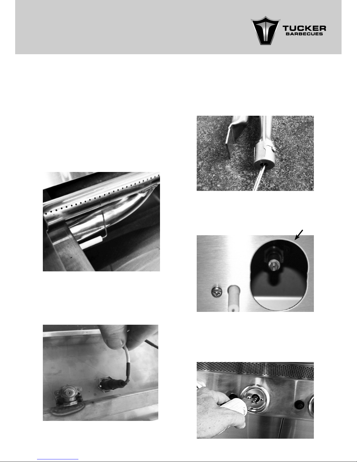
• Barbecue won’t light? Check all gas
connections and that the gas bottle has gas.
• Ignition is not working? Check the leads are
connected properly and adjust the spark
gap to make sure the gap is 4mm from the
ports on the burner. For Natural Gas it is best
to have the igniter probe just above the
ports on the burners and for L.P. Gas it is best
positioned just below the the ports on the
burners.
• Check that the ignition leads are connected
properly as the ignition lead might just need
to be rmly connected into either the ignition
probe or the ignition button correctly. The
lead may be damaged also.
• One of the burners won’t light? Check the
throat of the burner for a blockage, remove
the air mixture cap and gauze on the throat
of the burner and push a screwdriver up it to
clear the blockage.
• Control knobs are stiff? Remove the knobs
and spray the valve shaft with unceasing
lubricant then oil the shafts of the control
valves and replace the knobs.
TROUBLESHOOTING SOLUTIONS
Check the injector nipple that supplies the gas
to the burner it maybe has a blockage.
Valve injector
Page 22

22
• Barbecue doesn’t seem to be as hot
anymore? Check burner inlet and burner
port holes for blockages or regulator
pressure. Insects maybe in the burners.
Check the injectors are not blocked on the
control valves.
Page 23

23
SERVICE & MAINTENANCE
1. Before each use remove any accumulated
grease and other cooking residue. Fat/
grease res are not covered by warranty.
2. Your barbecue should be cleaned regularly
with hot soapy water and dried afterwards.
Do not use steel wool as it will leave steel
deposits on the surface of which can cause
rust. Scotch Bright pads can be used but will
generally leave scratch marks where you
have rubbed. Only use these on stubborn
un-washable deposits.
3. To remove rust marks, we recommend Eagle
One NEVER DULL wadding polish. To prevent
rust marks, polish the barbecue with stainless
steel polish regularly. Hint, rub the BBQ over
with a cloth after each use when the BBQ
is still hot and the grease on the BBQ will
wipe off easy and make it easy to look after
as it leaves a slight cover of grease on the
stainless steel which impedes the salt air
from settling in the pours of the stainless steel
surface.
4. Grease or oil the shafts of the gas control
valves where they enter the alloy housing
every 3 months to avoid them ceasing up. If
they become hard to turn or if you smell gas,
get the BBQ serviced.
5. Periodically check the leads on the ignitions
for cracks or the connections to the probes
or buttons.
6. Do not attempt to dismantle control valves
or the regulator.
7. Periodically remove the burners and
scrub them with soapy water and a wire
brush. Make sure the ports are clear from
obstructions, unscrew the air mixture cap
and gauze from the throat of the burner
periodically and brush away any dust, spider
webs or insect nests that may have built up,
replace them and screw them back on.
When replaced turn each burner on and
check that the ame pattern is good, you
can adjust the air mixture by turning the
cap on the end of the burner throat open or
closed. You want a blue ame with a yellow
tip.
8. Check hose and regulator regularly and
replace if damaged.
9. It is recommended that the hose and
regulator be replaced every 5 years.
10. If you cannot operate the barbecue
correctly turn it off. Do not continue to use
it. Take it back to the place of purchase or
local dealer and get them to test and repair
it.
11. Stainless Steel barbecues can be affected
by high temperatures of which can cause
discoloration on the BBQ frame.
12. Check and tighten nuts and bolts on the
barbecue regularly.
13. A canvas cover will help keep your
barbecue protected from weather. Make
sure the barbecue is dry before putting the
cover on or corrosion may occur. Coastal
climates are particularly vulnerable to this.
14. Check all connections for gas soundness.
15. Warning: Servicing must only be carried out
by authorized personnel.
16. This appliance must not be modied.
17. Check gas cylinder regularly for test date
status.
18. We recommend service of this appliance to
be done by an authorized person every two
year.
FOR SERVICE OR REPLACEMENT PARTS,
CONTACT YOUR NEAREST DEALER OR VISIT
www.tuckerbbq.com.au
Page 24

24
WARRANTY
TUCKER GTR BARBECUE WARRANTY
WARRANTY PERIOD
NOT COVERED
CONDITIONS OF THIS WARRANTY
Stainless steel body
Gas manifold
Stainless steel burners
Cross lighting panel
Gas control valves
Flare Guards
Grease collection
tray
Ignitions
All other parts
10 years
Lifetime
2 years
2 years
1 year
2 years
5 years
1 year
1 year
The warranty does not cover the purchaser or
any other person for damage malfunction or
loss due to the following:
• Lack of maintenance, abuse, neglect,
misuse, accident, or improper installation of
this appliance.
• Scratches, dents or discoloration caused by
heat, abrasive or chemical cleaners.
• Damage due to grease or fat res.
• Failure of burners and valves due to insect
blockage.
• Distortion of are guards.
• Surface rust.
• Cleaning and normal wear and tear.
• Unauthorized repairs during the warranty
period.
• Removal or re-installation costs.
SERVICE CALLS OF THE ABOVE NATURE ARE
CHARGEABLE
1. The appliance is delivered to TUCKER
AUSTRALIA distributors service department
or authorized service agent and freight
charges both ways is to be paid by the
owner. No liability is accepted for loss or
damage during transit.
2. The appliance is installed by a qualied
person and operated and maintained in
accordance with the instructions supplied.
Repairs and service must be carried out by
an authorized person.
3. Installation must conform to the standards
laid down by the local codes or, in the
absence of local codes, with AGA code
AG:601 AS:5601:2002
4. No alterations or repairs are to be carried
out without obtaining the distributors prior
consent. Such repair or any replacement
does not extend the warranty period.
5. Proof of purchase together with this warranty
must be provided to verify purchase date
and establish the warranty period. Only
the original purchaser is covered under this
warranty.
6. Where this warranty is inconsistent with any
state laws, the rights of the purchaser shall
prevail.
7. Parts installed from other manufacturer’s
products will nullify this warranty.
FOR YOUR RECORDS
Model:
Serial Number:
Retailer:
Purchase Date:
Gas type:
TUCKER AUSTRALIA PTY LTD.
138 Silverwater Road
Silverwater NSW 2128 AUSTRALIA.
PHONE: (+612) 9748 8368
FAX: (+612) 9748 8138
WEB SITE: www.tuckerbbq.com.au
EMAIL: [email protected]
 Loading...