

Page 1
ASSEMBLY AND INSTALLATION INSTRUCTIONS
GTR BARBECUE INSULATION JACKET
MODELS:
GTR3, GTR4, GTR5, GTR6.
GTR3 SS, GTR4 SS, GTR5 SS, GTR6 SS.
GTR3 S, GTR4 S, GTR5 S, GTR6 S.
IMPORTANT – PLEASE READ ALL INSTRUCTIONS
BEFORE YOU ASSEMBLE, INSTALL OR
OPERATE THIS APPLIANCE.
Page 2

CONTENTS
GENERAL WARNINGS
INSULATION JACKET
ASSEMBLY INSTRUCTIONS
INSTALLATION INSTRUCTIONS
& WARNINGS
DIMENSIONS
3
4
8
10
2
Page 3

IMPORTANT SAFETY
INSTRUCTIONS
• Tucker GTR Barbecues are approved for
outdoor use only.
• Remove all plastic protection lm from
stainless steel components before assembly.
• Keep this manual for future reference.
• Read all instructions carefully before
assembly and usage of barbecue.
• Clean your barbecue regularly; check the
grease trays for excess grease build up as
damage by grease or fat re is not covered
by warranty.
• Always turn off the gas supply when you
nish barbecuing.
• A canvas cover for this barbecue will extend
its life and ensure trouble free operation.
• For installation of this barbecue onto its
cabinet refer to relevant instructions.
• Attend an operating barbecue at all times.
• Do not use this appliance indoors or in any
enclosed area.
• Read all instructions carefully before
assembly and usage of the barbecue.
• Do not use or store ammable materials in or
near this appliance.
• Always leak test /check hose connections
after lling cylinders.
• Check cylinder condition for rust and that
the date stamp is current as every gas
cylinder in Australia must be pressure tested
every ten years.
• Never disconnect the barbecue whilst it is
running.
• Do not modify this appliance in any way.
• Do not allow children to operate the
barbecue.
• If a grease/fat re should arise, turn off the
gas supply immediately until extinguished.
• Always open the Lid or Roasting Hood before
lighting.
• Do not spray aerosols in the vicinity of this
appliance while it is in operation.
• Do not place articles on or against this
appliance.
WARNING FOR
YOUR SAFETY
If you smell gas:
1. Shut off gas supply to appliance.
2. Extinguish any open ame.
3. Open lid or hood.
4. If odour continues, immediately call your
gas supplier or your Fire Department.
HAZARDOUS FIRE OR EXPLOSION MAY
RESULT IF INSTRUCTIONS ARE IGNORED.
It is the consumer’s responsibility to see that the
barbecue is properly assembled, installed and
taken care of. Failure to follow the instructions in
this manual could result in serious bodily injury
and /or property damage.
3
Page 4
INSULATION JACKET
ASSEMBLY
JACKET ASSEMBLY
Tools required for assembly – Phillips head
screwdriver and shifting spanner.
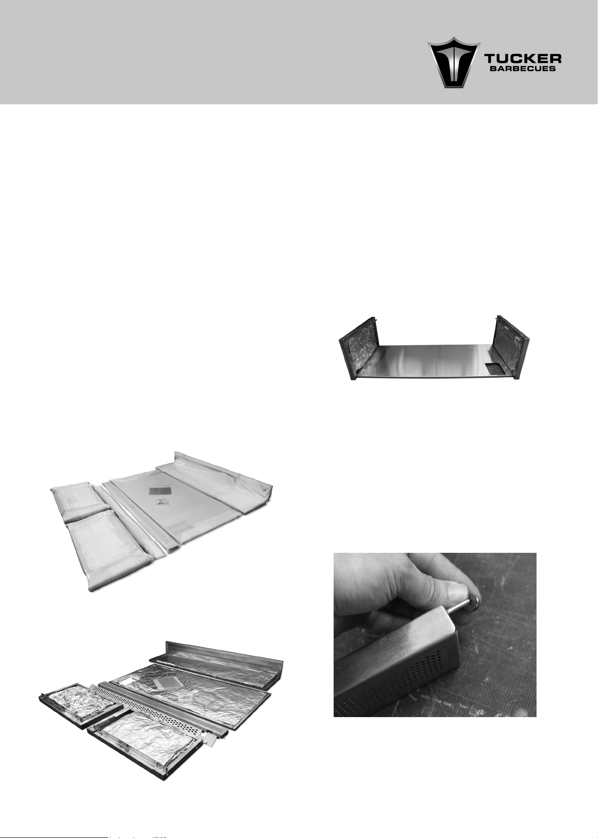
• Unpack and check that you have all
components before building the Insulation
Jacket.
INSULATION JACKET PARTS LIST
• Left side panel and insulation wool.
• Right side panel and insulation wool.
• Base panel and insulation wool.
• Small hose cover panel and 2 x nuts and
bolts.
• Rear Back Panel and insulation wool.
• BBQ Front angle panel.
• Drip tray fascia panel.
• Packet of nuts and bolts.
1. Attach left and right hand side panels to the
base panel with the 6 bolts as per photo.
We recommend you remove the insulation
wool from the panels for this process and
have the side panels at and the base panel
vertical so that the bolts drop down into the
holes to make it easier to bolt the panels
together.
Do not tighten the bolts up.
2. Now attach the front drip tray fascia panel
to the front of the jacket, the front fascia
panel has a pin on either side of it, that
locates into the holes on either side of the
side panels.
The pins allow the drip tray fascia panel to
fold up and down.
2.1. Insert spacer into the pin.
4
Page 5

2.2. Insert the right hand side pin into the
jacket.
3. Now attach rear back panel to the left
and right hand side panels using the bolts
attached to the rear of the side panels.
In the back of each side panel there is a
plate with nuts welded into it of which is used
to attach the bolts to the side panels.
Once the rear panel is attached you can
tighten all the other nuts and bolts up rmly.
2.3. Loose the Left hand side pin.
4. Place the jacket into or onto the benchtop
The rear back panel of the jacket can be
adjusted in height to suit the thickness of
your bench top surface.
Loosen off the bolts on the rear panel, this
will allow you to lift the rear panel up or
down, you may choose to run the stone
bench top over the rear panel or lift it up
so that it is ush with your benchtop surface
then tighten the bolts to secure it in place.
2.4. Insert the left hand side pin into the
jacket and tight in up.
4.1. Adjust the back panel to your desired
height.
5
Page 6

4.2. Once the back panel is adjusted, then
tighten all the bolts.
5. Before securing the Insulation Jacket to the
cabinetry or bench you will need place
the Insulation Jacket into position and mark
the position where the hose and regulator
needs to penetrate through. (The regulator
penetration hole size could be as large as
100mm for the large regulators).
You will need to measure the size of the
regulator you have before drilling the hole.
Alternately remove the hose from the BBQ
and you will only need to drill a small hole
through the bench for the hose to penetrate
through.
6. There is a small cover plate supplied with
the jacket that must be used to cover the
penetration hole in the base panel of the
jacket.
6.1. Once you have drilled the hole then you
have to attach the small hose cover panel
to the base panel.
6.2. Place the panel in place and tighten the
nuts and bolts together with a Phillips head
screwdriver and spanner.
7. Now line all sides of the jacket with the
insulation wool as well as underneath the
jacket and attach the hose to the inlet if you
have removed it from the BBQ inlet.
8. Now secure the jacket to the cabinetry or
bench.
9. Before placing the BBQ into the jacket you
have to attach the BBQ front angle panel to
the bottom of the BBQ front fascia.
This must be attached to reduce the chance
of gas entering the rebox of the BBQ in
case there is a leak from the gas supply.
6
Page 7

10. Do not secure the BBQ to the jacket if the
jacket is going to be inserted between two
cabinets, this will allow you to simply place
the BBQ into the Jacket and if need be,
allow you to remove the BBQ from the jacket
later on if servicing is required.
If the BBQ and jacket are simply sitting on
top of a benchtop then you can bolt the
BBQ into the jacket using the holes on either
sides of the jacket side panels.
10.1. Attach the insulation Jacket using four
bolts to secure the jacket to the BBQ.
10.2. Once the BBQ will be placed into the
Jacket it will look like this image above.
7
Page 8

INSTALLATION INSTRUCTIONS
& WARNINGS
BARBECUE INSTALLATION INSTRUCTIONS
READ THE IMPORTANT INFORMATION
ON THE FRONT OF THE BARBECUE.
For installation onto a GTR trolley read relevant
instructions.
This barbecue is designed and approved for
outdoor use only.
Be mindful of the location of the installation of
the barbecue.
If you are using the roasting hood it is better that
the prevailing wind blows into the front of the
BBQ during cooking.
NOTE: Strong winds blowing into the back or
aross the back of the hood whilst cooking with
the hood closed can cause overheating of
the BBQ. Hot air retained in the hood during
cooking may not be able to be released
naturally from the rear vent of the hood in
strong winds.
• At least 30% of the remaining wall area is
open and unrestricted.
• In the case of balconies, at least 20% of the
total of the side, back and front wall areas
shall be and remain open and unrestricted.
DIAGRAMMATICAL REPRESENTATIONS OF
OUTDOOR AREAS
The following gures are diagrammatical
representations of outdoor areas. The areas
used in the gures below are examples – the
same principles apply to any other shaped
area.
FIGURE F1 – OUTDOOR AREA – EXAMPLE 1
INSTALLATION WARNINGS
Do not use this appliance indoors or on marine
craft.
This appliance shall only be used in an above
ground, open-air situation with natural
ventilation, without stagnant areas where
gas leakage and products of combustion
are rapidly dispersed by wind and natural
convection.
Any enclosure in which the appliance is used
shall comply with one of the following:
• An enclosure with walls on all sides, but at
least one permanent opening at ground
level and no overhead cover. (gure 1)
• Within a partial enclosure that includes an
overhead enclosure and no more than two
walls. (gure 2 and 3)
• Within a partial enclosure that includes an
overhead cover and more than two walls,
the following shall apply. (gures 4 and 5)
FIGURE F2 – OUTDOOR AREA – EXAMPLE 2
• At least 25% of the total wall area is
completely open.
8
Page 9

FIGURE F3 – OUTDOOR AREA – EXAMPLE 3
Both ends open
FIGURE 4 OUTDOOR AREA –EXAMPLE 4
FIGURE F5 – OUTDOOR AREA – EXAMPLE 5
Open side at least
25% of total wall area
OPEN SIDE AT LEAST 25% OF TOTAL WALL AREA. 30% OR
MORE IN TOTAL OF THE REMAINING WALL AREA IS OPEN
AND UNRESTRICTED.
30% or more in total
of the remaining wall
area is open and
unrestricted.
Open side at least
25% of total wall area
30% or more in total
of the remaining wall
area is open and
unrestricted.
OPEN AT SIDE AT LEAST 25% OF TOTAL WALL AREA. 30% OR
MORE IN TOTAL OF THE REMAINING WALL AREA IS OPEN
AND UNRESTRICTED
9
Page 10

DIMENSIONS
DIMENSIONS OF GTR INSULATION JACKET
(Measurements are in mm)
Model (A)
GTR SS 280 680 465
GTR 3 280 680 600
GTR 4 280 680 760
GTR 5 280 680 920
GTR 6 280 680 1080
(B)
(C)
B
Model (A) (B) (C)
GTR 3+1 280 680 1020
GTR 4+1 280 680 1180
GTR 5+1 280 680 11340
GTR 6+1 280 680 1500
C
10
A
Page 11

RECOMMENDED CUT-OUT SIZES FOR
GTR BBQS WITH INSULATION JACKET FITTED
(Measurements are in mm)
Model (D) (E) (F)
GTR SS 280 680 470
GTR3 280 680 605
GTR4 280 680 765
GTR5 280 680 925
GTR6 280 680 1085
Model (D) (E) (F)
GTR3SS 280 680 1025
GTR4SS 280 680 1185
GTR5SS 280 680 1345
GTR6SS 280 680 1505
NOTE: Gas manifold inlet is 20mm in width,
depth and 20mm hight below grease tray.
PLAN VIEW
R
I
G
H
T
-
H
A
N
D
S
I
D
E
FOLLOWING ARE THE CLEARANCES SURROUNDING
A TUCKER BBQ WHEN IT IS INSTALLED INTO A TUCKER
INSULATION JACKET.
Zero clearance to combustibles on the sides of
the BBQ.
Zero clearance to combustibles on the base of
the BBQ.
Zero clearance to combustibles on the rear of
the BBQ.
800mm clearance to combustibles above the
BBQ.
FRONT
MINIMUM CLEARANCES ABOVE COOKING
SURFACE OF BBQ TO COMBUSTIBLE WALLS
Rear Wall 100mm
Side Walls 100mm
Above BBQ with out Roasting Hood 800mm
Above BBQ from top of Roasting Hood 800mm
NOTE: If the walls surrounding the BBQ are within
100mm of the BBQ or within 200mm from the
rear of the BBQ, they must be made from non
combustible material.
If they are further away than 100mm on the
sides and 200mmm at the rear then combustible
material is okay to be used.
11
Page 12

TUCKER AUSTRALIA PTY LTD.
138 Silverwater Road
Silverwater NSW 2128 AUSTRALIA.
PHONE: (+612) 9748 8368
FAX: (+612) 9748 8138
WEB SITE: www.tuckerbbq.com.au
EMAIL: mail@tuckerbbq.com.au
 Loading...