

Page 1

OPERATING INSTRUCTION MANUAL
SPARE PARTS CATALOGUE
HKM SWEEPER
November 2007
Page 2

Contents
1 General Information .....................................................3
1.1 Intended Purpose............................................................3
1.2 Data concerning the product ..........................................3
1.2.1 General................................................................3
1.2.2 Manufacturer's address ......................................3
1.2.3 Marking................................................................3
1.2.4 Information Required for Orders ........................3
1.3 Technical data.................................................................4
2. Safety..............................................................................5
2.1 Basic safety rules............................................................5
2.2 Marking conventions in the manual ...............................5
2.3 Safety rules for the operator...........................................5
2.4 Personnel qualification and training...............................6
2.5 Safety rules for working on the sweeper.......................6
3. Operation ................................................................
.......
7
3.1 Assembly instructions.................................
....................
7
3.2 Preparing the machine for the initial use
.......................
8
3.3 Notes on use ................................................................
...
9
Startinq the Motor
Turning the motor off
Drivinq the sweeper
Drivinq speed
Brush drive
Brush speed
Settinq brush height
Settinq brush angle
Extras
4. Maintenance ................................................................
10
4.1 General..........................................................................
10
4.2 Adjusting the drive belt tension ....................................
10
4.3 Troubleshooting ............................................................
10
Parts Catalogue ...................................................................11
Diagram 001 ..........................................................................12
Diagram 002 ..........................................................................14
Diagram 003 ..........................................................................16
Diagram 004 ..........................................................................18
Accessories............................................................................20
Page 3

2
Page 4

3
General
1 General Information
1.1 Intended Purpose
The HKM sweepers were specially developed for sweeping and show clearance.
Any other application should be discussed with the manufacturer prior to that use. Any damage caused by
usage outside these areas are fully at the risk of theuser. The content of this manual describes correct usage
and maintainance of themachine.
1.2 Data concerning the product
1.2.1 General
This manualis validforall theHKM sweeper series.
1.2.2 Manufacturer's address
Tuchel Maschinebau GmbH
Holsterfeld 15
48499 Salzbergen
Telephone +49(0) 5971 9675-0
Fax +49 (0)5971 9675-30
E-Mail: service@tuchel.com
1.2.3 Marking
Marking is by means of the vehicle identification plate.
NOTE
Write your sweeper’s datais here, so that youalways have the information to hand.
Model/Type
Serial No.
Year of
construction/Order No.
Max.oil pressure (bar)
Max.oil flow (L/min)
Gross weight (kg)
WARNING
The identification plate serves a legal function and as such must not be changed or defaced so
as to be unreadable.
NOTE
Replace those that are damaged or missing.
1.2.4 Information Required for Inquiries and Orders
When ordering spare parts or requesting information about the sweeper, quote the model, serial number and
year of manufacture of the machine.
WARNING The use of spare parts from other manufacturers is not permitted without the
express written
permission of Agriquip. The use of original spare parts protects the machine and ensures its safe
operation. The use of other than original partsor accessoriesrenders the warranty null and void.
WARNING
Neither the manufacturer nor their agents are responsible for any consequences arising from the
use of non-original parts or unapproved attachments.
Page 5
4
General
1.3 Technical data
NOTE
for enginespecifications refer to the motor instruction booklet (included)
Working width HKM 100 : 1000 mm HKM 120 : 1200 mm
Distance between wheels 560 mm
Height including engine 600 mm
Brush diameter 330 mm
Driving speed 2.5 – 4.5 kph
Weight 85 kg
Tyre pressures Main wheels: 1.5 bar (max2.5 bar).
Support wheel: 1 - 2 bar (max2 bar).
Engine
Use 91 Octane petrol
Honda GCV 160 or Honda GXV 140
or Briggs& Stratton5HP I/C
Oil 10W 40
Vibration through hand and
arm on the handle bars.
a
hwd
= 3.6 ms-2(Honda)
a
hwd
= 3.5 ms-2(B&S)
Maximumnoise level
L
WAd
= 94dB(A)/1pW (Honda)
L
WAd
= 93dB(A)/1pW (B&S)
Noise level at operator’s ear
L
pAd
= 84dB(A)/20 Pa (Honda)
L
pAd
= 84dB(A)/20 Pa (B&S)
Optional extras Collector, Snow Plough
Page 6

5
Safety
2. Safety
2.1 Basic safety rules
This handbook contains safety information concerning the operation and maintenance and SHOULD BE
READ PRIOR TO OPERATING OR MAINTAINING THE SWEEPER.
Failure to observe these safetyrules canendanger the operator and cause damage to the environment.
Failure to conformto these rules removes all possible claimsfordamage.
The following dangers should be especially considered:
Danger to people coming into the working area because it has not been properly secured or cordoned off.
Failure of important machine functions.
Failure to carry out correctmethods of service andinspection.
Endangering people mechanically and chemically.
Endangering the environment with petrol and oil leaks.
ATTENTION
In addition to the included operating instructions and safetyrulesand notices, therequirements
of the relevant DoL-OSH Guidelines should be observed.
ÿ
Please also heed of the safety notices and precautions of the engine manufacturer.
2.2 Marking conventions in the manual
The safety notes contained in this manual, which endanger persons ifneglected, are flagged with
the general safety symbol
ÿ
Safety notes, whose neglect would cause dangers for the machine, have the word ATTENTION
inserted.
Notes are indicated as follows: NOTE
At the machine these safety symbols must be taken notice of and must be kept in good readable condition.
2.3 Safety rules for the operator
Before starting the machine familiarise yourself with all the controlsand their functions.
Only start the machine when safety devices and covers are inplace (especially the drive belt cover).
When using the machine wear suitable clothing and strong shoes. Do not wear loose clothing
ÿ
scarves or dressesthat could be caught upin the broom.
Secure the machine against running away or against the use of the machine by unauthorised third parties.
Check that there is enough petrol before starting. Do not fill the tank with petrol etc in anenclosed room or
while the machine is running orhot. Wipe any petrol spills from the machine before startingor wait until
theyhave evaporated.
Other than when filling the motor tank with petrol the tankcap shouldalways be keptfirmly closed. When
handling petrol, fires, welding, smoking, andother potential ignition sources are forbidden.
If the petrol tank or the tank cap are damaged they must be replaced immediately
Never start the motor inan enclosed room, there is a danger of carbon monoxide poisoning.
Always operate the sweeper at an appropriate speed for the location and conditions.
When working onslopes or steep areas please note there is a danger of the machine tippingover or rolling
away from the operator. (Do not relyon the broom as a brake).
Keep handsand feet clear of rotatingparts.
Ensure the area is clear of people and animals before commencing sweeping.
Do not allow people and animals into thearea while operatingthe sweeper.
Do not carry passengers on themachine!
Before cleaning, inspection, repair or maintenance work, ensure that all moving parts have come to a
complete standstill. Set the gas lever to STOP andremove the spark plug lead to prevent starting.
Never leavethe machine unattended when the motor is running.
Let themotor cool before storing the machine away in an enclosedroom.
Page 7

6
Safety
2.4 Personnel qualification and training
The sweeper may only beoperated, maintained and repaired by competent persons, that have been fully
informed about the associated dangers. The area of responsibility, the competence and the monitoring of the
personnel must be regulated by the operator. If the personnel do possess thenecessary knowledge, then
theyare to be supervised and given instruction. Further it is to be verified by the operator that the contents of
the manual are fully understood byallpersonnel.
Those repairs and adjustments not describedin this manual, may only be performed by authorised agents.
2.5 Safety rules for working on the sweeper
Before cleaning, inspection, repair or maintenance work, ensure that all moving parts have come to
a complete standstill. Set the gas lever to STOP and remove thespark plug lead to prevent starting.
Only the service, inspection and maintenance work described in this operating manual should be
ÿ
carried out by the owner. All other workshould be performed by an authorised dealer.
Once themachine has been turned off a number of parts including the silencer remain hot for an extended
period.
If guards and covers have been removed(especially the belt cover) there is a danger of entrapment
trapping extremities with painful or damagingresults. Replace all guards and covers before re-startingthe
machine.
The operating and maintenance instructions in the motor manufacturer’s handbook should befollowed.
NOTE
Signs attached to the sweeper must be maintained in good readable condition.
Missing or damaged signs must be replaced.
Page 8

7
Operation
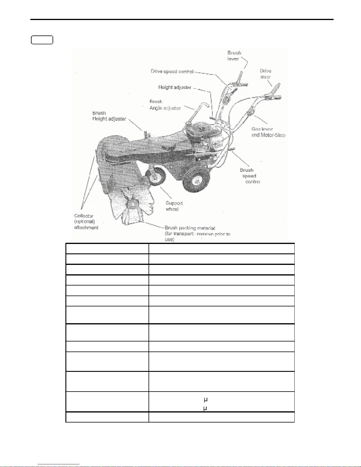
3. Operation
1. Throttle and motor stop.
2. Operating lever for the sweeping brush
3. Operating lever for the forward drive
4. Speed selection lever
5. Height adjustment for handles
6. Motor
7. Brush angling lever
8. Drive belt cover
9. Height adjustment for the brush
10. Support wheel
11. Attachment for collector etc.
12. Sweeping brush
13. Swivel locking for brush
The HKM 100 and HKM 120 machines come in 2 cartons.
Carton 1 – Main part with the motor mounted
1 Sweeper power component
2 Wheels
1 Cover
1 Power transmission cover
1 Packet containing: instructions and spares list, engine instructions & small components
Carton 2 – Front part with the brushsystem
1 Sweeper front part including brush
1 Swivelling lever
1 Power transmission belt
1 Power transmission belt cover
1 packet containingassembly components
After opening the topof the carton slit twosides down to the bottom, the machine maythen be rolled out.
3.1 Assembly instructions.
a)
Attach the handles to the machine body using the boltsand washers provided. The front and back plates
of the handle structure are bolted together with M8 nuts and bolts.
b)
Attach the driving wheels with the air valves facinginwards.They are pushed onto the axle and secured
with asplit pin.
ÿ
Be careful not to get your fingers caught between the parts.
c) Mountthe brush.
Remove the M12 nutfrom the brushcore.
Remove the washer and brush end plate.
Push the brush segment into position making sure it goes correctly onto the square core.
Push the brush drive component onto the core andfinally the second brush segment.
Re-attach the end plate washer and nut.
d) Attach the brush angling lever7.
Slide brush angling lever through guides (as shown in diagram at top of page).
Attach to the brush cover using the circlip.
Page 9

8
Operation
e) Attach the support wheel.
f) Attach brush height adjustment handle (inthe pack containing small parts).
Place a washer over the thread and screw thehandle into the hole (M – asin diagram at top of
previous page) until the machine starts to lift.
Note: When the machine is complete the brush should be adjusted until it makes a light contact with
the ground. The
pressure should never press the brush more than 15mm into the ground.
When the right height is achieved the handle is secured with the lever.
g) Fit drive and sweeping modules together.
Referring to figure at right, bring both parts
together.
Push the shaft L through the connecting
piece C andthe drive belt pulley
Secure by inserting the split pinF.
Check the diagram to make sure that the
positionof C is correct (refer step h).
ÿ
Be careful not to get your fingers caught.
h) Attach the drive belts.
Ensure that the throttle is at the motor stop
positionand remove the spark plug lead.
Draw the drive belt over the motor pulley.
This machine may be operated at 2 different brush speeds.
This is achieved by sel ecting one or other of the belt pulleys
Upper drive bel t pulley — Faster brush speed (e.g. for snow)
Lower drive bel t pulley — Slower for general sweeping.
Ease the belt over the sweeping drive pulley. You may assist this to go over by pulling the starter
cordbut do not get your fingers in the way.
Note: The belt must be in the guide way and lay correctly on the pulleys and on the inner side of the
tensioner. This is
important because it will ensure that the drive disengages properly (
ie. when the brush lever is released the brush
does not continue to rotate) – refer to D.3 if problems occur.
i) Attach the drive belt cover (The drive belt cover is in two parts so that the rear pulleymay be covered
when thedrive part of the machine is attached to other devices).
Bringthe rearpart into position and screw into place
Screw the front piece into place, laying correctly on the profileshape of the rear cover.
ÿ
The operation of the machine without the drive beltcover is strictly forbidden.
3.2 Preparing the machine for the initial use
Lift the leverof the brush swivellingarm and use it to move the brush to a normal position. Pull the support
wheel up, taking care that it does not catch inthe cable.
Turn the support wheel height adjustment until the wheel
comes into contact with the ground. The washer should be
between the tube andthe base of the handle.
The next item to deal with is the swivelling arm. The arm is slid
through the eye and mountedon the swivelling point. When
tightening the swivelling point ensure that the plastic washer
can still be turned by hand. The ratchet positioning needs to be
fixed on with the M12 nut.
Next remove the transport supports from the ends of the brush.
ÿ
Use gloves when doing this to avoid injury from the brush
or the edges of the metal.
Tightenthe nut on the brush rotational point carefully.
ÿ
Prepare the engine (read the engine handbook
). The engine is delivered without any oil(use 10 W 40).
All HKMengines use 91 octane lead free petrol.
Page 10

9
Operation
3.3 Notes on use
Prior to startingthe machine familiarise yourself with the controls. The machine has controls for brush and
machine driving speed. The brushand drive operation levers are dead man levers and will go tothe off
positionif released.T he ergonomic design means that little pressure is required to keepthe machine running.
If the levers are released the machine will stop.
Startinq the Motor
If the motor has a petrol tap turn this on.
Move the gas control to MAX which puts the engine in the choke position.
Using either the elector start or the pullstart cordstart the motor.
After a fewsecondsyou can move the gas control lever back off of choketo the fullspeed position.
Turning the motor off
Move the gas control lever to theStop position
If presentturn off the petrol cock.
ÿ
Warning after the motor is turned off the motor partsare still hot for quite some time.
Drivinq the sweeper
To startthe machine moving forward gripthe red lever on the left handle bar (as seenfromthe operator
position). You will need to hold the lever down, if you let go the machine will stop.
Drivinq speed (2.5 –4.5 kph)
The sweeper has a speed control on the left handle bar (as seen bytheoperator).
Move the lever forward to increase speedand backwards to decrease speed. This can be done white the
machine is running.
Brush drive
The brush is started by pressing down the red lever on the right hand handle bar (as seen by the operator).
You will need to hold the lever down to keep the brush rotating. If you let go the brush will stop.
ÿ
When you start the brush rotating it will be in contact with the ground. If the nature of the ground is such
that the brush can not freely rotate, the brush rotation will move the sweeper forward. It is better to put
the machine in drive first and move forward at thedesiredspeed then startthe brush.
Brush speed
Fivebrush speeds can be selected on this machine. While the brush is running youcan operate the speed
control leveron the lower part of the left handle bar (as seenby the operator).
Move the lever first towards the machine centre and then upor down.
Settinq brush height ( brush pressure)
The brush should have a contact area with the ground as seen from the side of between 15 and 20 mm.
Loosen the contra nut and rotate the handle (9 – on figure on page 7) until the brush looks right on the
ground. Then re-tightenthe locking nut..
Settinq brush angle
If you are using the-collector the brush head should be keptstraight. Angle the brush to sweep off to one side.
Raise the lever (13 – on figure on page 7
), move brush around todesiredangle, then lower the lever to lock
it into thenew position.
Extras
The mostimportant and useful extra is a collector.
To attachit simply lower it onto the 2 pin holders on the brush head.
If the conditions are very dusty a water spray systemis ideal for keeping the dust down. This is simple to
attach and a worthwhile extra.
It is possible to attach a snowplough to thesweeper for dealing with larger quantities of snowthan the brush
will deal with. It should also be noted thatthe correct brush for snow is the 8 x 2 Polypropylene.
Snow chains are alsoavailable for the machine toimprove the grip in snow.
Page 11

10
Maintenance
4. Maintenance
4.1 General
You have purchased a virtually free maintenance machine. Generally speaking the sweeper is service free
apart from the motor. This means there is no general maintenance work.
In order to keep the machine in good general working order and maintain the value of the machine the
operator should note the following:
Motor-oil level: Check before each machine use. (see EngineHandbook)
Air filter: Check regularly that the air filter is in order and leta dealer clean it once a year with a pressure
cleaner. If the machine is being used ina very dustyenvironment the user should ask the dealer how to
check the filter regularly.
Cleaning: The machineshould be washedoff with a gentle water spray and normal car cleaning materials
can be used. Do not use High pressure washers they will damage seals on service free bearings.
Check cables for wear: The lever operated by the cable must be freely moved by the springiness of the
inner cable. Do not grease the operating levers. If the cable length needs adjusting this is achieved by
altering the adjustment screw at the operating lever (like bicycle brakes).
Tyre pressure: All 3 wheels havecar tyre valves. The support wheel pressure should bebetween1.5 and
2.2 bar. The driving wheels 1.8 bar.
The wheels should beremoved once a year and a small quantity of grease applied to the moving parts.
Handle bar height adjustment: Move the locking lever up andforward (do not hit it against the motor) adjust
the handle bar height to whatis requiredand lock the lever back. Adjust the butterfly nut to tighten.
Winter storage: If the machine is to be stored for a long period of time contact your dealer who will make
the most suitable recommendations.
4.2 Adjusting the drive belt tension
ÿ
A Warning there is a danger of trapping your fingers
If the drive starts to loose the forward motion it is probably
necessary to re-tension the drive belt tensioner. This is not
something that will happen often.
Isolate the motor by removing the spark plug lead.
Remove the rear plate of the motor section of the
machine.
Loosen the nut on the tensioner
Using a lever press the idler pulley onto the belt.
Re-tighten the nut.
4.3 Troubleshooting
The motor does not start Gas lever not in ‘Max” position
Spark plug removed or dirty
Spark plug lead removed
Petrolis empty or tap is closed
Brushstops occasionally Clutch cable needs adjusting (if this does notcure the problem
consultyour dealer)
Machine will not run straight Tyre pressures different
Pull sharplyto one side to resynchronise forward drive
Snow gets stuck between brush and casing The snow is too high to brush. Use snowploughattachment
Snow clogging brush Snow is too wet for a nylon brush, use a poly 8x2 brush
Page 12

11
HKM 100/120 Sweepers
Parts Catalogue
Page 13

12
Parts Catalogue
Diagram 001
Page 14

13
Parts Catalogue
HKM 100 / 120 Parts List Diagram 001
Item Part N° Description Item Part N° Description
1 FKN-101 Brush Cover (1m) 37 4HJ-D021 Plastic Spacer
2 4HJ-X17 End Cover 100/120 38 FKN-101 Brush Cover (1.2m)
3 4H 0 S44Z1 Flathead Screw M6x15 39 FKN-229 Brush 33/49
4 4HW-B06ZI Spacer, Large E6 40 4KH-P01 Parallel Key 7x8x80
5 4HR-00621 Locking Nut M6 41 FKA-1112 Brush Driver
6 4HU-A501 Snap Ring 50 42 EKN-133Z Neck Camp 33149
7 FKN-202 Brush 33/44 43 FKB-1102 Transmission Flange
8 4HO A23Z1 Screw M10x20 44 4KB-S01 Gearbox VF49
9 4HW-F10 Z1 Lock Washer M10 45 4HL-A01 Snap Ring
10 4H0 A07Z1 Screw M6x12 46 4HW-P511 Close Tolerance Spacer
11 4HW-F06 di Lock Washer M 6 47 4KH-P05 Parallel Key
12 FFKN-1162 Neck Camp 33/44 48 4DA-L01 Spacer
13 4HU-142 1 Snap Ring 42 49 4HO-A25Z1 Screw M10x30
14 FKN-117 Oscillating Brush 3/44 50 4HR-C10Z1 Locking Nut M10
15 4HA-A20 Ball Bearing (60042RS} 51 4DC-H32 Oscillating Brush
16 4HU-A201 Snap Ring 20 52 4HX-G301 Clamping Sleeve 6x30
17 4DS-CO1 Star Washer 22 53 4KC-B10_ Clutch Ring, Upper
18 4HK-E11 Balance Buffer 54 4KC A20 Clutch
19 4KH-PO4 Parallel Key 55 4KC~A18 Clutch Ring, Lower
20 4KB-S05 Gearbox VF44 56 FKA-1412 Brush Axle 1.2m
21 4HK A02 Snap Ring 30 57 4HR-G12Z1 Locking Nut M12
22 4AZ-107 Z Brush Driver 44
23 4170-B01 Driver Shaft
24 4HW-B12Z1 Spacer, large E12
25 4DA-E03Z Spacer
26 FKA 140 Z Brush Axle 1m
27 FKN-203 Swivelling Support
28 4HK-S01 Silent Block
29 4HJ-G02 Grasp Cover 15
30 4H0-A08Z 1 Screw M6x16
31 4HR-006 Z1 Stop nut M6
32 4AZ-A30 Z Plastic Spacer A100-20
33 4AZ-S01 Clamping Sleeves Set 1
34 4HO A61Z Screw M12x65
35 4HR-A12ZI Locking Nut M12
36 4HW-A12ZI Spacer E12
Page 15

14
Parts Catalogue
Diagram 002
Page 16

15
Parts Catalogue
HKM 100 / 120 Parts List Diagram 002
Item Part N° Description Item Part N° Description
1 FK N-108 Brush Carr ier 38 4HW-B10ZI Spacer, Large
2 4 HB -Z 23S Drive Belt, Front 39 4HO-N 80Z Duty Screw 3/8 UNC
2 4H B-Z 22S Drive Belt, Rear 40 4HUV F10 Z 1 Lock Washer M10
3 4AZ -V01 Variab le 41 4HR -A52Z Duty Nut
4 4H A-A10 Bal l B earing ( 6 002 RS ) 42 FKN-233 Assembly Plate
5 4HW-A10 Z1 Spa cer E 7 0 43 4HJ- A02 Flanged Bush
6 4KC-A461 Loc kin g Ring 10 44 4HO-1 73 Z 1 Closed Screw M8x16
7 FKN-114 Brush V-arm 45 4HW-F08 Z1 Lock Washer M8
8 4HW-A12 Z1 Spacer E 12 46 4HR A08 Z 1 Nut M8
9 4HX-E25 Z1 Split Pin 3.2x25 47 4DA-053 Cover
10 4HO-C43Z Screw M12x110 49 4H0-G 12 Z1 Inside Screw M8x12
11 4HR-C12Z1 Locking Nut M 12 50 4HR -C 08Z 1 Locking Nut M8
12 FKN-121Z Racing Clamp 51 4DC -K 07 Jackshaft
13 4DB-T02Z Supplement (only GXV 140) 52 4HX-H501 Clamping Sleeve 8x50
14 4HO-A14Z1 Screw M8x20 53 4HX-H361 Clamping Sleeve 8x36
15 4HW-A08 Z1 Spacer E 8 54 4AZ-A34 Z V-Dop Screw
16 4HR-108 Z1 Cage Nut 55 FKN-124Z Dome Half-washer
17 4HY-B071 Blind Rivet V2A 56 4HW-P59 Close Tolerance Spacer 25x1
18 4HA-Y25 Y-Camp 25 57 4DC-001 Z Ring 25
19 4HW-D08Z1 Spacer, Thick E 8 58 FKN-207 Dome Free-wheel 102
20 FKN-112Z Bearing Bolt 69 4HA-A25 Ball bearing (60052RS)
21 FTS-106 Z Bearing Guide 65 60 4HU-147 1 Snap Ring 47
22 4HO A07Z1 Screw M6x12 61 4DC-R10Z Cone Ring 25
23 4HR-006 Z1 Locking Nut M6 63 4HB-D24V
Drive Belt – Variable (VB 10x630)
24 4HO- A17Z1 Screw M6x30 64 4HB-A20V Drive Belt – Motor (VB 13x630)
25 4HW-B06 Z1 Spacer, Large E 6 64 4HB-X01S Drive Belt
only Honda (XPZ 13x950)
26 4HI-A02 Tension Spring 65 4DC-H29Z Drive Axle
27 4HO A13Z1 Screw M8x16 66 4HD-B56 Chain
28 4HO-A61 Z Screw M12x65 67 FKA-101 Chain Wheel
29 4HR-A12Z1 Nut M12 68 4HW-A20 Z Spacer E 20
30 FKN-115Z Dome Tension Adjuster 69 4HO-C18Z1 Screw M8x40
31 4HA-A12 Ball Bearing (60092Rs) 70 4KC-AO3Z Tension Ring
32 4AZ-A35 Z Clutch Roller 71 4HU-A201 Snap Ring 20
33 4DC-H31 Case 12-1O 72 4KC-B36Z1 Close Tolerance Spacer 20x1
34 4HB-X18S Drive Belt (XPA590) 73 4HJ-D03 Spacer 20
35 4KC-A211 Self-tapping Screw 74 4DA-104 Driver
36 4AZ-205 Id ler B2 75 4KH-X01 Parallel Key
37 4DC-M10Z Case KN 4 6 76 4DX-A03 Z Housing
Page 17

16
Parts Catalogue
Diagram 003
Page 18

17
Parts Catalogue
HKM 100 / 120 Parts List Diagram 003
Item Part N° Description Item Part N° Description
1 4HJ-X15 Belt Guard KN 30 4KC-B20 Pressure Screw
2 FKA-220 Crank - FKN-223 Gang Wheel complete
(Pos.31-37)
3 4DA-I01 Z Counter Shaft 31 FKN-110Z Wheel Fork
4 4HW-A10 Z1 Spacer E 10 32 4HW-A20 Z1 Spacer E 21
5 4HO S47Z1 Fixing Screw M8x15 33 410M-B01 2 Shaft Case
6 4HK-E011 Rubber Washer 34 4HO C43Z Screw M12x110
7 4DA-F46S Motor Mounting Plate 35 4HW-Al2 Z1 Spacer E 12
7 4DA-F47S Motor Mounting only GXV140) 36 4HR-Cl2Z1 Locking Nut M12
8 4HW-DO8Z1 Spacer, thick E 8 37 4HN-G01 Air Wheel 2.50-4
9 4HO A14Z1 Screw M8x20 38 4DA-054 Tail Plate
10 4AZ-S22 Engine Screw Set 39 4HO A13Z1 Screw M8x16
10 4AZ-S23 Engine Screws only GXV140) 40 4HW-A08 Z1 Spacer E 8
11 4DJ-D02 Z Case Nut 15 41 FKN-111Z Arm
12 4HW-FO8 Z1 Lock Washer M8 42 FKN-1292 Retainer
13 4HR-AO8 Z1 Nut M 8 44 4HW-B10 Z1 Spacer, Large E 10
14 4AZ-A03 Motor V-belt Pulley 45 4AZ-V01 Variable
15 4KC-A041 Grub Scr ew M8x10 46 4HA-A10 Ball Bearing (60002RS)
16 4HK-S01 Spring Washer 47 4DM-P01 Case
17 4HO-G12 Z1 Inner Screw M8x12 48 FKN-112Z Bearing Bolt
18 4FIR-CO8Z1 Locking Nut M8 49 4HY-BO71 Blind Rivet V2A
19 4AZ-601 Fuel Pipe Honda GVC 50 4KB-S10 Motor Gearbox
19 4AZ-604 Fuel Pipe Honda GXV140 51 FKN-1342 Motor Gearbox Support
19 4AZ-607 Fuel Pipe B&S engine 52 4KC-A561 Screw M5x16
20 4HO-174 Z1 Lock Screw M6x60 53 4AZ-301 Z Flange Bearing 12
21 4HW-A06Z1 Spacer E 6 55 4AZ-A45 Z Motor Spacer
22 4HR-C06 Z1 Locking Nut M6 56 4HX-F251 Clamping Sleeve 5x25
23 4DB-S05Z Flat Bar 57 4HE-804 Pinion 10
24 4HR-CIO Z1 Locking Nut M10 58 4HX-F201 Clamping Sleeve 5x20
25 4HW-A10 Z1 Spacer E 10 59 4HB-D25 V
Drive Belt – Variable (VB 10x450)
26 4HR-A10Z1 Nut M10 60 4HN-G02 Air Wheel 4.00-4
27 FKN-113Z Round Bar 61 4KC-B36Z1 Close Tolerance Spacer 20x1
28 4HX-E25Z1 Split Pin 3.2x25 62 4AZ-801 Z Klapp Split Pin 8/ 32
29 4H1-B04 Compression Spring
Page 19

18
Parts Catalogue
Diagram 004
Page 20

19
Parts Catalogue
HKM 100 / 120 Parts List Diagram 004
Item Part N° Description Item Part N° Description
1 FKN-119 Steering Wheel 102 37 4HR-A06Z1 Nut M6
2 4HO-A14Z I Screw M8x20 38 4AZ-711 Variable Cable
3 4HW-A08 Z1 Spacer E 8
4 4HR-C08Z1 Locking Nut M8
5 FKN-213 Steering Wheel Toggle
6 4DJ-D02 Z Case Nut 15
7 4HR-K10Z Wing Nut 10
8 4KC-B33 Eye Bolt
9 4HW A12 Z1 Spacer E 12
10 4KC-A15 Spring Washer 12
11 4HJ-G08 Case 12
12 FKN-1302 Shift Lever
13 4HJ-G02 Case 15
14 4HO-A73Z1 Screw M6x35
15 4HW-B06Z 1 Spacer, Large E 6
16 4HI-B05 Compression Spring
17 4DC-F40Z Centerer
18 4HW-A06Z1 Spacer E 6
19 4HR-006 Z7 Locking Nut M 6
20 4KC-A051 Clamping Cap 8
21 4HY-A07ZI Rivet 6x25
22 4HJ-X18 Cap
23 4KC-A08 Clamping Cap 6
24 FKN-127 Link 102
25 4DA-F50Z Bowden Cable Support
26 4HU-A41Z1 Screw M6x40
27 4HO-A74Z1 Screw M6x60
28 4KC-B35Z Rest Screw 102
29 4AZ-709 Clutch Cable (Brush)
30 4HO-G41 Z Inner Screw M6x40
31 4HJ-G03 Handle 25
32 4AZ-713 Clutch Cable (Drive)
33 4AZ-710 Clutch Cable (Drive Dble Gearbox)
34 4HI-AO1 Tension Spring 01
35 4HI-A02 Return Spring
36 4DA-F41 Z Shift Lever
Page 21

20
Parts Catalogue
Accessories
For Collector For Snow Plough
Item Part N° Description Item Part N° Description
1 4HK-E14 Rubber Border 1 m (upper) 8 4HK-E05 Digging border 100 (rubber)
1 4HK-E17 Rubber Border 1,2m (lower) 8 4HK-EO6 Digging border 120 (rubber)
2 4AZ-S06 Screw Set Rubber Border 9 4DB-B07 Rail 100n)
3 FKG-115 Z Swiveling Adapter 2 9 4DB-B08 Z Rail 120
4 4HK-16 Dust Border 1 m 10 4AZ-S08 Screw Set Digging Border
4 4HK-E18 Dust Border 1.2 m 11 4KC-A27 Z Sharpening Skid (only l.2m)
5 FKG-203 Swivel Roller (incl. 6) 12 4HO-A36Z1 Screw M12x40
6 4AZ-S07 Attachment Set Swivel Roller (2x) 13 4AZ-S09 Supporting Rubber Set
(incl. screws)
7 4HY-B05 S1 Blind Rivet, long
Note:
The DIN and standard parts from this listare delivered predominantly in packing units.
If the last place of the part is a "1“, then this means a packing unit of 10 pieces.
Examples: 4HW A10 Z 1 =10 StarWashers DIN 125 10.5
4HU-A20 1 = 10 pieces snap ring for wave brush 20
Page 22

Imported and Distributed by:
P.O. Box 578 30 Hurlstone Drive New Plymouth
(06) 759 8402 N EW PLYMOUTH
 Loading...