

Tubeline TL50LSV Operator's Manual
Tubeline Manufacturing Limited
6455 Reid Woods Drive RR #4
Elmira, Ontario, Canada N3B 2Z3
Email:
Toll-free (North America): 1.888.856.6613
sales@tubeline.ca
Fax: 519.669.5808
Tel: 519.669.9488
www.tubeline.ca
Operator’s Manual
Keep this manual with the machine at all times.
Balewrapper
TL50LSV
Rev. 1-0
Do not attempt to operate this machine without thoroughly
reviewing this manual for safe and proper operation.
PRINTED IN CANADA
43686
Operator’s Manual
Thank you for choosing the Tubeline TL50LSV Balewrapper. Our hope is that it will give you many
years of productive service. This machine is designed to wrap bales in a continual line with plastic
lm. Please read and understand this manual and the machine before operating.
Advantages to High Moisture Hay
High moisture hay has many advantages over traditional dry hay.
High moisture hay provides:
• Lower harvesting time
• Cuts to feeding costs
• Increases ADG (Average Daily Gain)
• Minimizes storage loss
• Less reliance on favorable weather.
To learn more about this process visit
http://tubeline.ca/silage.php
Advantages to Wrapping Bales
Using an inline bale wrapper to protect your product provides a cost and time efcient means of bale
storage and limits spoilage of bales.
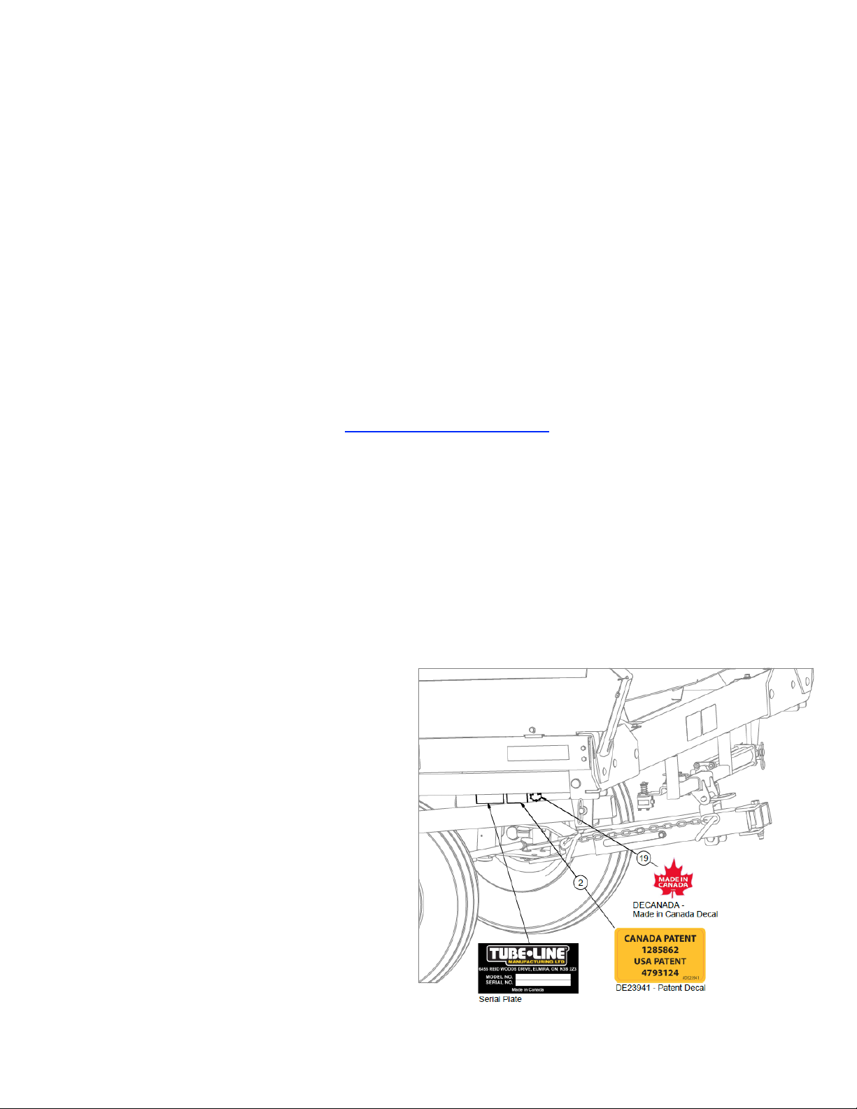
Serial Number
The implement serial number is located on the front left corner of the frame. (See below) This
number helps us to track changes and improvements and must be mentioned when ordering parts or
requesting service. For your convenience, a space has been provided inside the front cover of this
manual to record the serial number, model number, purchase date, and dealer name.
Model # : ____________________________
Serial # : ____________________________
Date Purchased : _____________________
Dealer Name : _______________________
Engine Model # : ______________________
Engine Serial # : ______________________
TL50LSV -
Operator’s Manual
I

Inline Wrapper 3 Year Limited Warranty Statement (Excludes Individual Wrapper)
All Equipment is sold subject to mutual agreement that it is warranted by Tube-Line Manufacturing
Ltd (hereinafter the company) to be free from defects in material and workmanship. The company’s
liability shall be limited exclusively to the original owner to replace or repair without charge, at its
factory or elsewhere, at its discretion, any defects in material or workmanship which become apparent
in the rst year from the date on which the equipment was purchased. In the second and third year
the company will supply at no charge replacement of defective parts only. Installation and freight will
be at the expense of the owner.
Components supplied by third parties and not manufactured by the company will carry such warranty
as extended by such parties, such as but not limited to, tires, batteries, electrical components,
hydraulics and engines.
The buyer by the acceptance of the equipment will assume all liability for any damages which may
result from accident, abuse or misuse by his employees or others. Any equipment that has been
altered or modied without prior written authorization by the company will render the warranty null and
void.
No employee or representative of the company is authorized to make changes to this warranty or
grant additional warranty terms unless authorized in writing by management of the company.
The company shall not be liable for special, indirect or consequential damages of any kind including
but not limited to, loss of revenue, rental replacement costs or other losses.
Normal wear and tear from normal use of the equipment is not warranted. The end user is expected
to maintain and service the equipment in accordance with accepted practices. Failure to do so will
void the terms of this warranty.
Warranty coverage is null and void unless Warranty Registration form has been completely lled in
and is on le at Tube-Line Manufacturing Ltd.
NOTE: Newest manual version can be found at
www.tubeline.ca/support
II
Operator’s Manual
- TL50LSV

Table of Contents
Operator’s Manual I
Advantages to High Moisture Hay ...........................................................I
Advantages to Wrapping Bales .............................................................I
Serial Number ..........................................................................I
Inline Wrapper 3 Year Limited Warranty Statement
Section 1: General Information 1-1
Usage ..............................................................................1-1
Suitable Wrapping Timeframe ............................................................1-1
Bales ...............................................................................1-1
Wrapping Straw .......................................................................1-1
Dimensions ..........................................................................1-1
Orientation ...........................................................................1-2
Terminology ..........................................................................1-2
Section 2: Safety 2-1
Safety Signal Words / Safety Messages ....................................................2-1
Safety Guidelines .....................................................................2-1
Personal Protective Equipment ...........................................................2-2
Lighting .............................................................................2-2
Safety Decal Locations .................................................................2-4
Safety Decal Illustrations ................................................................2-5
(Excludes Individual Wrapper) .................II
Section 3: Control Panel 3-1
Control Panel Functions ................................................................3-1
Control Panel Functions - Optional ........................................................3-2
Section 4: Adjustments 4-1
Door Switch Adjustment ................................................................4-1
Bale Ram Limit Switch Functions .........................................................4-1
Bale Ram Limit Switch Adjustments .......................................................4-2
Plastic Film Installation .................................................................4-3
Section 5: Hydraulic Functions 5-1
Flow Control Adjustment ................................................................5-1
Directional Control Valve Functions ........................................................5-1
Steer Speed Needle Valve Adjustment .....................................................5-2
Section 6: Setup 6-1
Dealer Installation .....................................................................6-1
Battery Hookup .......................................................................6-2
Pre-Operating Inspection ................................................................6-3
Manual Mode Test Run .................................................................6-3
Auto Mode Test Run ...................................................................6-3
Wrapping Site ........................................................................6-3
TL50LSV -
Operator’s Manual
III

Section 7: Operation 7-1
Balewrapper Starting ...................................................................7-1
Starting a Bale Row ....................................................................7-1
Auto Wrap Mode ......................................................................7-2
Steering .............................................................................7-2
Stopping Cycle .......................................................................7-2
Optional Remote Start ..................................................................7-2
Ending Bale Row ......................................................................7-3
After Wrapping ........................................................................7-4
Section 8: Transporting Balewrapper 8-1
Transport Lock ........................................................................8-1
Disconnect Battery ....................................................................8-1
Fuel Shutoff - 13hp Engine Only ..........................................................8-1
Power Unit Hookup ....................................................................8-1
Slow Moving Vehicle (SMV) Sign .........................................................8-2
Observe Maximum Transport Speed .......................................................8-2
Tire Pressure .........................................................................8-2
Storage .............................................................................8-2
Section 9: Feeding 9-1
Feeding from Bale Row .................................................................9-1
Plastic Film Disposal ...................................................................9-1
Section 10: Maintenance 10-1
Grease Points .......................................................................10-1
Grease Timeline .....................................................................10-2
Hydraulic Oil ........................................................................10-2
Hydraulic Oil Filter ....................................................................10-2
Section 11: Diagnostics 11-1
Control Panel Relays ..................................................................11-1
Electric Hydraulic Sequence of Operation ..................................................11-1
Manifold Port Connections .............................................................11-2
Troubleshoot Plastic Film and Carriers ....................................................11-3
Section 12: Option - Remote Control 12-1
Remote Control Installation .............................................................12-1
Remote Control Function ...............................................................12-1
Option - Remote Control Start Add-on* ....................................................12-2
Remote Start Add-on Installation .........................................................12-2
Remote Start Add-on Operation .........................................................12-3
Section 13: Option - Plastic Film Sensor 13-1
Film Sensor Installation ................................................................13-1
Plastic Film Sensor Adjustment ..........................................................13-2
Plastic Film Sensor Operation ...........................................................13-2
Section 14: Option - Wireless Plastic Film Sensor 14-1
Wireless Film Sensor Reciever Board Installation ............................................14-1
Wireless Film Sensor Transmitter Installation ...............................................14-2
Wireless Film Sensor Test ..............................................................14-2
Wireless Film Sensor Operation .........................................................14-2
IV
Operator’s Manual
- TL50LSV

Section 15: Option - Dispatch Arm 15-1
Dispatch Arm Installation ...............................................................15-1
Dispatch Arm Operation ...............................................................15-2
Section 16: Option - Guide Roller Kit 16-1
Guide Roller Kit Installation .............................................................16-1
Section 17: Option - Night Light Kit 17-1
Night Light Kit Installation ..............................................................17-1
Night Light Kit Operation ...............................................................17-1
Section 18: Option - Twin Wrap Kit 18-1
Twin Wrap Kit Installation ..............................................................18-1
Twin Wrap Kit Adjustments .............................................................18-1
Twin Wrap Plastic Film ................................................................18-2
Section 19: Option - Laser Guidance System 19-1
Laser Guidance Installation .............................................................19-1
Laser Guidance Wiring ................................................................19-2
Laser Guidance Adjustment ............................................................19-3
Laser Guidance Control Screen Functions .................................................19-3
Main Menu Screen ...................................................................19-3
Laser L Screen ......................................................................19-3
Main Menu: Count Bales Screen .........................................................19-4
Section 20: Option - Roadex Suspension Axle 20-1
Suspension Axle Installation ............................................................20-1
Imperial Torque Value Chart VII
Metric Torque Value Chart VIII
TL50LSV -
Operator’s Manual
V

Intentionally Left Blank
Section 1: General Information
Usage
This machine is designed to wrap round bales in a continual row with plastic lm.
Suitable Wrapping Timeframe
Use a hard-core baler to make the well-shaped and rm bales necessary for successful wrapping.
Bales are best wrapped as soon as possible after baling. If bales are left unwrapped they will sag and
lose shape. Heating will start soon after baling and protein quality will be lost. It is desirable to wrap
within four hours. In an emergency, the bales can be left 12 to 16 hours.
The Tubeline wrapper makes timely harvest possible by reducing the dependence on the weather.
It is much easier to get to wilt silage than to make dry hay. This also extends the working day, as the
correct moisture to bale extends earlier and later in the day.
For more information visit
http://tubeline.ca/silage.php
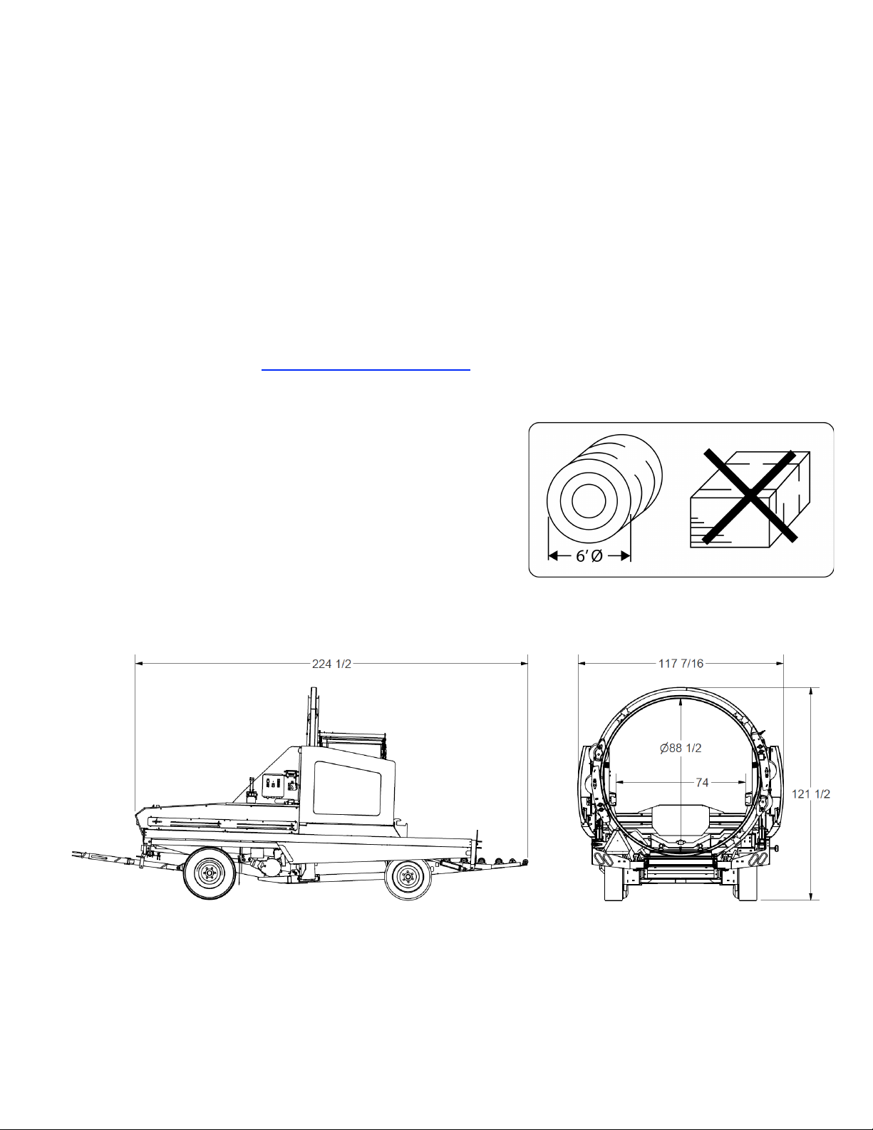
Bales
The TL50LSV will wrap round bales up to 6’. This machine
is NOT intended to wrap square bales.
Wrapping Straw
Only two layers of plastic are necessary to weather-protect
straw with the TL50LSV. Dry straw may be wrapped
continually without spaces. Straw with moisture is best
wrapped with spaces in the plastic.
Dimensions
TL50LSV -
Section 1: General Information
1-1
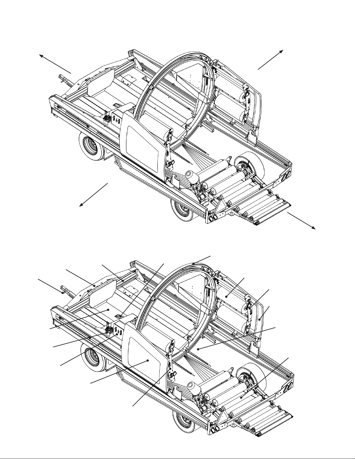
Orientation
Directional references in this manual are dependant on the operator’s position from a forward pointed
position while towing this machine.
Front
Right
Left
Common terms used in this manual.
Final Bale Pushoff
Bale Ram
Tongue
Bale Deck
Directional
Control Valve
Control Panel
Left Safety Guard
Terminology
Bale Trigger
Rear
Hoop
Plastic Film
Plastic Film Carrier
Right Safety Guard
Wrap Chamber
Roller Bed
1-2
Plastic Film Carrier
Section 1: General Information
- TL50LSV

Section 2: Safety
NOTE: This safety alert symbol is found throughout this manual to call attention to instructions
involving yourself and others working around the machine.
Failure to follow these instructions can result in injury or death.
This symbol means:
• Attention!
• Become Alert!
• Your Safety is involved!
Safety Signal Words / Safety Messages
CAUTION: Indicates a potentially hazardous situation that may result in injury.
WARNING: Indicates a potentially hazardous situation that could result is serious injury or death.
DANGER: Indicates a hazardous situation that needs to be avoided. Operator needs to be aware of
these dangers. High probability of serious injury or death.
NOTE: Indicates an informative non-safety related message.
Safety Guidelines
Take the necessary precautions to avoid injury or death. These include:
• Have training and train new operators.
• Review the safety instructions with all users annually.
• Know where safety decals are and what they convey.
• DO NOT paint over, remove or deface any safety signs or warning decals on your equipment.
• Replace damaged and/or missing safety decals.
• DO NOT operate without fully installed shields.
• Reinstall any removed shields BEFORE operating.
• Inspect machine before operating.
• DO NOT operate this machine while under the inuence of drugs or alcohol.
• DO NOT let children ride or operate this machine.
TL50LSV -
Section 2: Safety
2-1
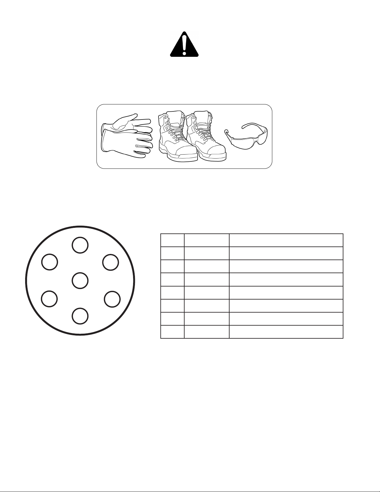
Personal Protective Equipment
WARNING: Wear work boots, gloves, and safety glasses when maintaining or repairing machine.
WARNING: Wear work boots and ear protection when operating machine.
DANGER: Do not wear loose clothing when operating of maintaining the TL50SLV.
Lighting
This machine is equipped with lights and reectors as required by the most stringent government and
ASAE specications. They connect to power unit’s 7-pin receptacle.
7 Pin Connector Wiring:
1
2
7
3
4
7-Pin Connector Front
PIN WIRE FUNCTION
1 White Ground
6
2 N/A N/A
3 Yellow Amber Running Light / Left Turn
4 N/A N/A
5
5 Green Amber Running Light / Left Turn
6 Brown Red Brake Lights
7 N/A N/A
2-2
Section 2: Safety
- TL50LSV
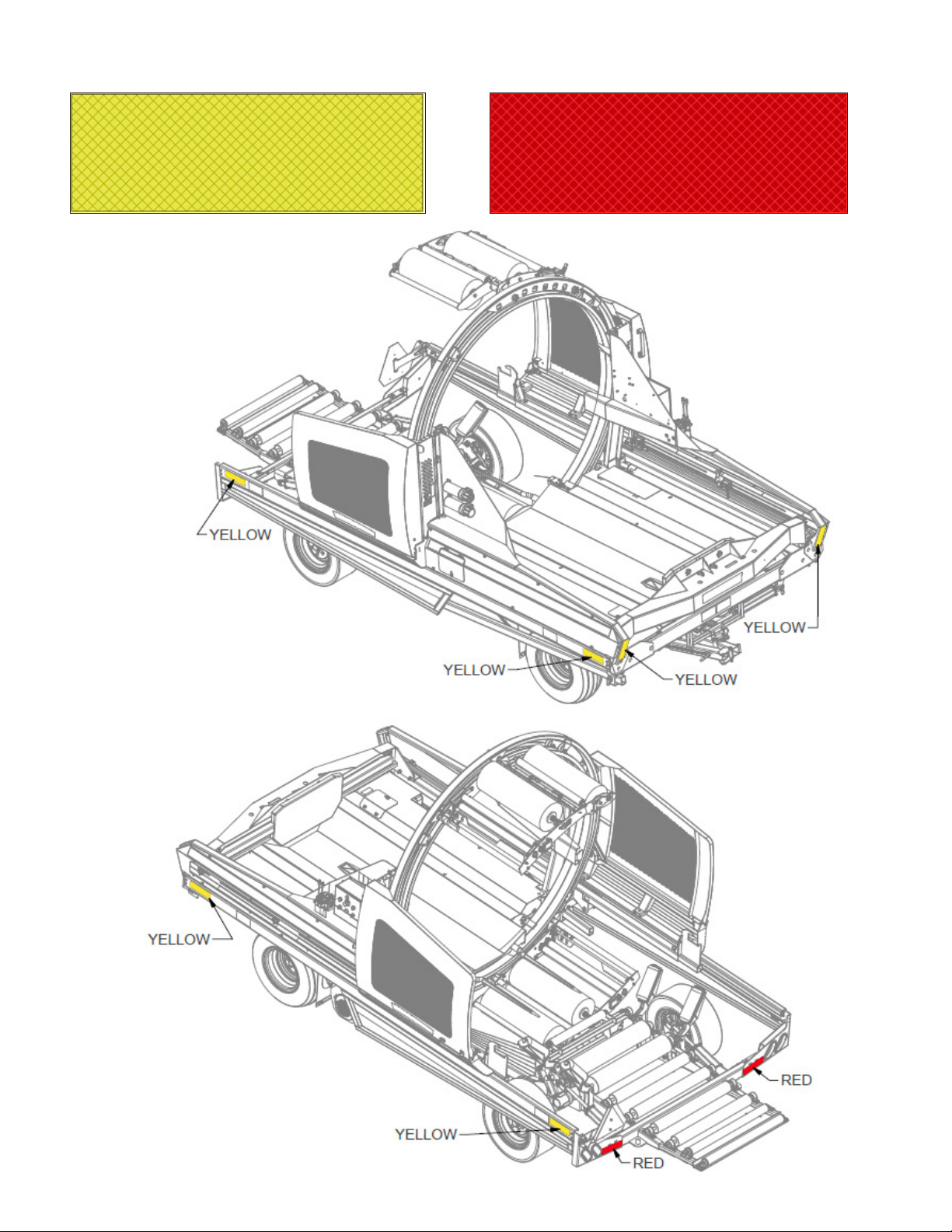
Clearance Markers
Part No: DEAMBER
Part No: DERED
TL50LSV -
Section 2: Safety
2-3
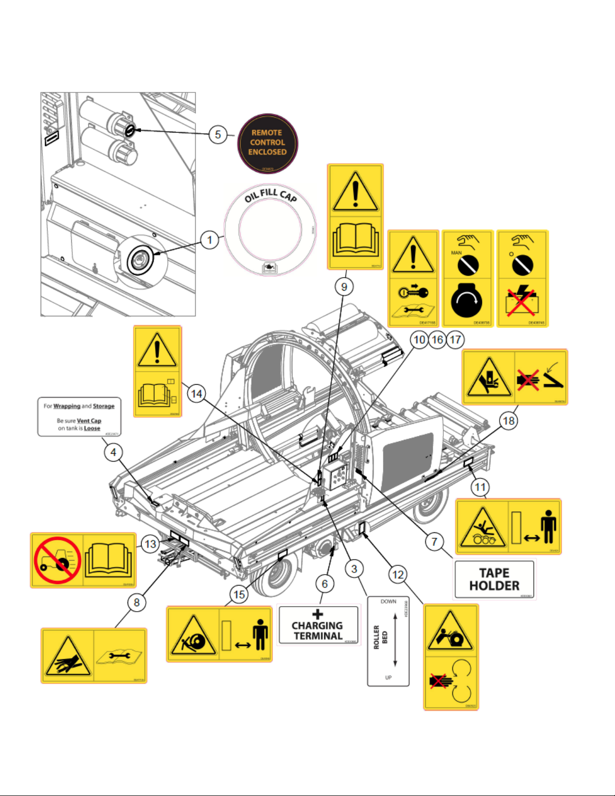
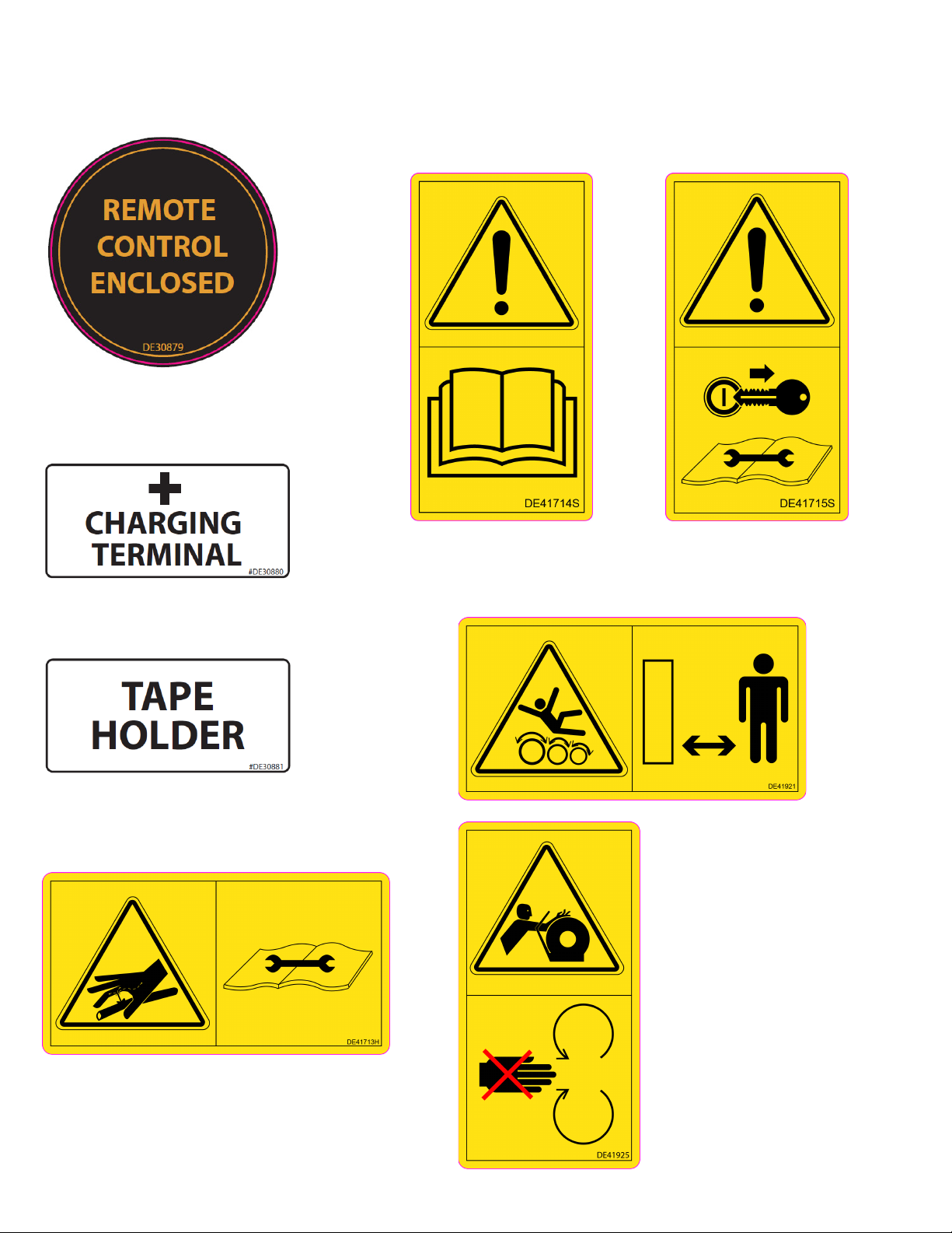
Safety Decal Locations
NOTE: Decals shown are not to scale.
2-4
Section 2: Safety
- TL50LSV
ITEM QTY PART NUMBER DESCRIPTION
1 1 DE30871 Oil Fill Decal
2 1 DE23941 Canada/USA Patent Decal
3 1 DE23968 Roller Bed Decal
4 1 DE23971 Wrapping and Storage Decal
5 1 DE30879 Remote Enclosed Decal
6 1 DE30880 Charging Terminal Decal
7 2 DE30881 Tape Holder Decal
8 1 DE41713H ISO Decal - High Pressure Fluid Horizontal
9 1 DE41714S ISO Decal - Read Operator’s Manual
10 1 DE41715S ISO Decal - Remove Key Before Repair
11 2 DE41921 ISO Decal - Do Not Stand on Rollers
12 1 DE41925 ISO Decal - Hoop Wheel Entanglement
13 1 DE41935H ISO Decal - Transport Speed Limit
14 1 DE42784S ISO Decal - Read OM Decal Section
15 2 DE43049 ISO Decal - Wheel Crush
16 1 DE43873S ISO Decal - Engine Start in MAN
17 1 DE43874S ISO Decal - Panel OFF Before Boosting
18 1 DE43875H ISO Decal - Hand Crush
19 1 DECANADA Decal Made In Canada
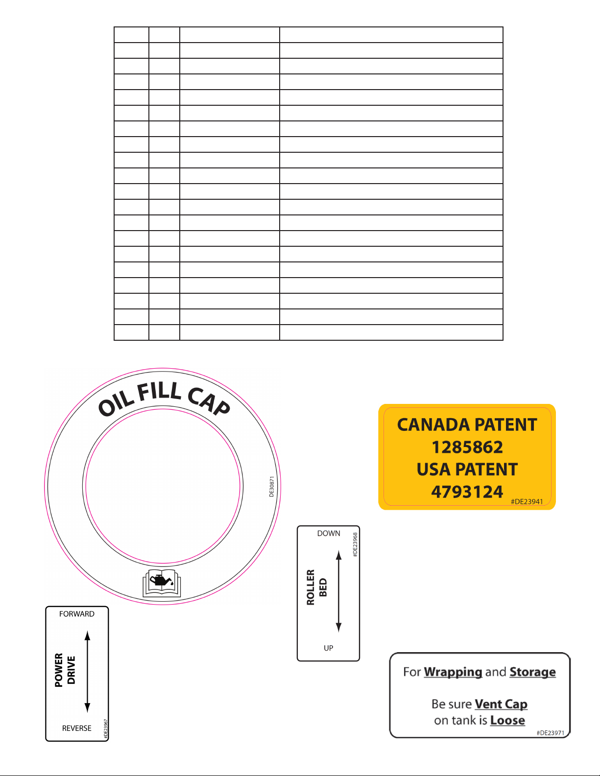
Part No: DE30871
Item: 1
Oil Fill Cap decal,
use AW32 SAE10 oil
when relling.
Safety Decal Illustrations
Part No: DE23941 Item: 2 (See
Canada, United States patent information decal.
Part No: DE23968 Item: 3
Decal shows hydraulic lever function for raising
or lowering the rear roller bed.
pg.I
)
Part No: DE23971 Item: 4
Loosen vent cap on top of fuel
tank to release any fume build-up.
TL50LSV -
Part No: DE23967 (Req. Powerdrive Option)
Decal shows hydraulic lever function for driving the
machine forward or reverse.
Section 2: Safety
2-5
Safety Decal Illustrations
Part No: DE30879 Item: 5
Remote Control Enclosed decal.
Part No: DE30880 Item: 6
Positive charging terminal for use a
battery boost.
Part No: DE41714S Item: 9
Read this manual and learn
the machine functions before
attempting to wrap bales.
Part No: DE41715S Item: 10
Read this service manual before
attempting repairs, remove key from
engine before attempting repairs.
Part No: DE30881 Item: 7
Wrap tape can be stored on this holder.
Part No: DE41713H Item: 8
Do not use hand to check for hydraulic
leaks, alternatively use a piece of cardboard.
Part No: DE41921 Item: 11
Do not stand on rollers, stand clear of machine while in
operation. Use caution when attempting repairs in this area.
Part No: DE41925 Item: 12
Entanglement hazard, do not
remove wheel drive shield while
engine running.
2-6
Section 2: Safety
- TL50LSV

Safety Decal Illustrations
Part No: DE41935H Item: 13
Do not exceed top speed of 32km/h
(20mph) while transporting this machine.
Part No: DE42784S Item: 14
Read the decal section of the operator’s manual
to understand potential hazards to avoid.
Part No: DE43059 Item: 15
Keep clear of wheels when machine
in operation and transportation.
Part No: DE43873S Item: 16
Turn control panel to manual
wrap mode (MAN) before starting
engine.
Part No: DE43875H Item: 18
Use handle when lowering pivoting safety
guard to avoid pinching or crushing hands.
Part No: DECANADA Item: 19 (See pg.I)
Manufacturer of origin decal.
Part No: DE43874S Item: 17
Turn off engine power and control
panel before boosting battery.
TL50LSV -
Section 2: Safety
2-7

Intentionally Left Blank
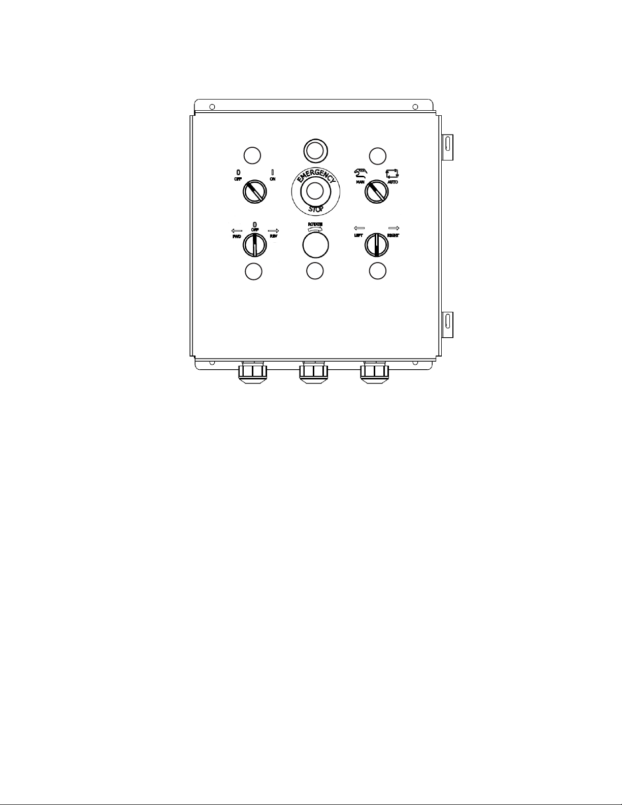
Section 3: Control Panel
Control Panel Functions
2
5
1
3
6 7
1. Manual Wrap Mode Light
Blinks red to indicate bale wrapper is in manual wrap mode.
4
2. 2-way ON-OFF Switch
Switch controls panel power. Turn left to cut power, turn right to power on control panel, switch will
light up green.
3. Emergency stop Push-Twist Release Knob (E-stop)
Push E-stop knob to cut power to entire bale wrapper, including the engine.Twist knob to end
emergency stop.
4. 2-way MAN-AUTO Wrap Mode Switch
Turn switch left to engage Manual wrap mode. Turn switch right to engage Auto Wrap mode.
5. 3-way Center Return Ram FWD-REV Switch
This switch will return to default OFF position when released. Turn switch to REV (REV = reverse)
to move a bale through the wrap chamber in manual wrap mode. Turn switch to FWD (FWD =
forward) to move bale ram towards front of the wrapper (home position).
6. Hoop Rotate Push Button
In manual wrap mode push and hold button to rotate hoop, applying plastic lm to advancing bale.
7. 3-way Center Return LEFT-RIGHT Steering Switch
This switch will return to default neutral position when released. Turn switch left or right to steer
the bale wrapper left or right. This function applies to both wrap modes.
TL50LSV -
Section 3: Control Panel
3-1
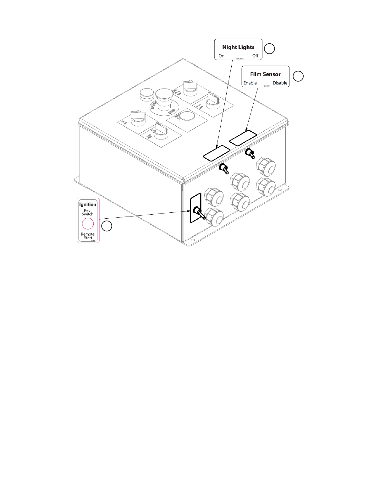
Control Panel Functions - Optional
1
2
3
1. Night Light Toggle Switch
Switch toggle to left side to turn on Night Light option, control panel must also be on.
2. Film Sensor Toggle Switch
Switch toggle to left side to enable Film Sensor option, control panel must also be on.
3. Remote Start Toggle Switch
Switch toggle to front position use key switch, disabling Remote Start option or switch toggle to
back position to enable Remote Start option (does not disable standard engine key switch start).
Control panel must also be on.
3-2
Section 3: Control Panel
- TL50LSV
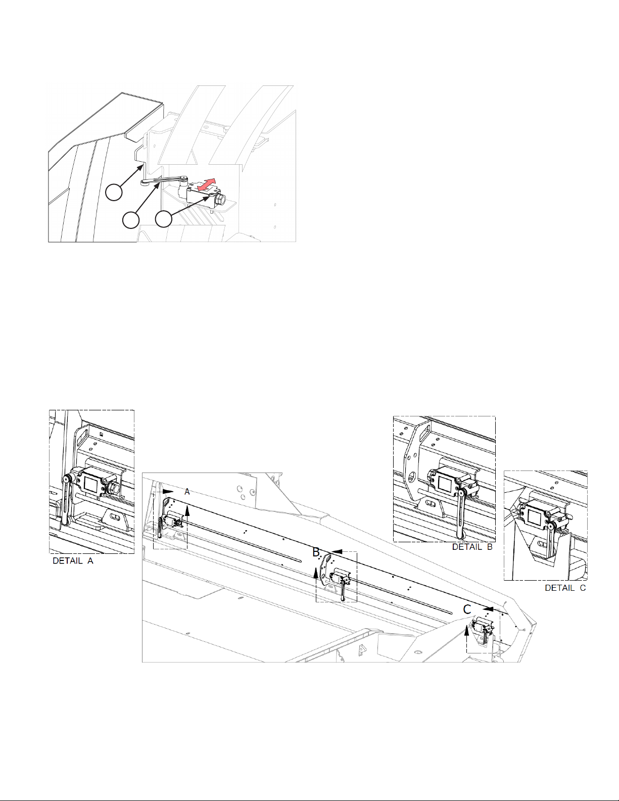
Section 4: Adjustments
Door Switch Adjustment
Top tab (A) of left safety guard must be fully closed
and contact the door switch arm (B) to engage auto
wrap mode. See Fig.1.
• Loosen 4 machine screws (C) and slide door
switch forwards if door switch does not contact
left safety guard tab.
A
Loosen 4 machine screws (C) and slide door switch
towards rear of machine if door switch arm contacts
B
C
safety guard tab before safety guard is fully lowered.
Bale Ram Limit Switch Functions
A. Bale Ram Reverse - Final Pushoff Limit Switch
Returns bale ram to home position when tripped in auto wrap mode. No function in manual wrap
mode.
B. Hoop Start Limit Switch
Starts hoop rotation in auto wrap mode when tripped. No function in manual wrap mode.
C. Bale Ram Home Limit Switch
Completes auto bale wrapping cycle by stopping bale ram retract when tripped.
TL50LSV -
Section 4: Adjustments
4-1
 Loading...