


2

TO THE OWNER
This manual contains information concerning the adjustment, assembly and maintenance
of your Tube-Line Chainless Bale Feeder. You have purchased a dependable machine,
but only by proper care and operation can you expect to receive the performance and long
life built into the Bale Feeder. Please have all operators read this manual carefully and
keep it available for ready reference.
Your authorized dealer will instruct you in the general operation of your Bale Feeder. Your
dealer’s staff of factory-trained service technicians will be glad to answer any question
that may arise regarding the operation of your Bale Feeder.
This safety alert symbol indicates important safety messages in this manual. When
you see this symbol, carefully read the message that follows and be alert to the
possibility of personal injury or death.
WARNING
Improvements
Tube-Line Manufacturing Inc. is continually striving to improve its products. We reserve the
right to make improvements or changes when it becomes practical and possible to do so,
without incurring any obligation to make changes or additions to the equipment sold
previously.
WARNING
Pictures in this manual may show protective shielding open or removed
to better illustrate a particular feature or adjustment.
Be certain, however, to close or replace all shielding before operating the machine
3

Contents
Safety…………………..…………..5
Parts ………………..…………….15
General information……..………34
Operation………………..……….40
Lubrication ……………………....42
Maintenance…………………..…44
Troubleshooting……………….…45
Optional Equipment………….…..46
4

Precautionary Statements
Personal Safety
Throughout this manual and on machine decals you will find precautionary
statements (“DANGER”, “WARNING”, and “CAUTION”) followed by specific
instructions. These precautions are intended for the personal safety of you
and those working with you. Please take time to read them.
This word “DANGER” indicates an immediate hazardous situation that, if not
avoided, will result in death or serious injury.
________________
DANGER
WARNING
This word “WARNING” indicates a Potentially Hazardous situation that, if not avoided,
could result in death or serious injury.
CAUTION
This word “CAUTION” indicates a potentially hazardous situation that, if not avoided,
may result in minor or moderate injury. It may also be used to alert against unsafe
practices.Failure to follow the danger warning and caution instructions may result in
serious bodily injury or death.
MACHINE SAFETY
The precautionary statement (“important”) is followed by specific
instructions. This statement is intended for machine safety.
IMPORTANT: The word “IMPORTANT” is used to inform the reader of
something he needs to know to prevent minor machine damage if a certain
procedure is not followed.
5

A careful operator is the best operator. Most accidents can be avoided by
observing certain precautions. To help prevent accidents read the following
precautions before operating this equipment. Equipment should be operated
only by those who are responsible and instructed to do so.
Carefully review the procedures given in this manual with all operators. It is
important that all operators be familiar with and follow safety precautions.
1. When transporting the machine on public
roads, make sure the machine is in
compliance with all local road regulation.
2. Before operating the unit be sure that it is
assembled correctly and in good
operating condition.
3. If machine maintenance work, repairs or
adjustments must be done in the field,
they should be done at a spot where the
ground is firm and level. Turn off the
tractor and apply the parking brake. Use
the proper tools and wear suitable
protection (safety goggles, work gloves,
etc.).
4. If any maintenance work, repairs or
adjustments are done which require
disassembly, always make sure that
everything is reassembled or retightened
as it has been prior to making repairs or
adjustments.
5. Follow the schedule provided for
maintenance. By following these
suggestions, it will be possible to keep the
machine operating safely and efficiently,
to the benefit of the user.
6. General checking of bolts, security pins
and split pins must be carried out initially
after the first 8 hours of use.
Subsequently, check every 50 hours and
whenever the machine is laid up for
extended periods.
7. Before applying pressure to the
system, be sure all connections are
tight and that hoses and
connections are not damaged.
8. Fluid under pressure can have
sufficient force to penetrate the
skin, causing serious personal
injury. Always protect the skin and
eyes from escaping fluid under
pressure. If injured by escaping
fluid, obtain medical assistance at
once. Serious infection or reaction
can develop if medical treatment is
not administered immediately.
9. Do not weld on wheels. Welding on
wheels may cause high stress and
a wheel failure.
10. Do not weld on wheels with a
mounted tire. Welding on wheels
with a mounted tire may cause the
tire to burst, causing serious injury
or death.
11. Before leaving the cab, engage
the parking brake, shut down
engine, and wait for all moving
parts to stop.
12. Always keep bystanders away
from machine during operation,
Rotating elements may cause
serious bodily injury.
Safety
Precautionary Statements
6

General Safety
YOU are responsible for the safe operation and maintenance of your Tube-line Chainless Bale
Feeder. You must ensure that you and anyone else who is going to operate, maintain or work around
the Bale Feeder be familiar with the operating and maintenance procedures and related safety
information contained in this manual.
Remember, YOU are the key to safety. Good safety practices not only protect you but also the
people around you. Make these practices a working part of your safety program. Most accidents can
be prevented. Do not risk injury or death by ignoring good safety practices.
Review the operating instructions for this header at least once a year per OSHA regulations 1928.57.
Know the meaning and location of each decal before operating the BF5000.
Watch for this symbol in this manual and on the Bale Feeder:
1. Keep a first aid kit in the cab for emergencies and know how to use it.
2. Do not allow any one to ride on the Bale Feeder while it is in motion.
3. Clear the area of bystanders, especially small children before starting the Bale
Feeder.
4. Do not allow anyone to operate the Bale Feeder who has not been instructed in
how to use the machine.
5. All operators should familiarize themselves with the safety section in the
operator’s manual.
6. Some pictures or illustrations may not show protective shields in place. Make
certain that all protective shields are in place before operating the machines.
Operating and Maintenance safety
1. DANGER, DO NOT stand around or near the Discharge or bed area. Objects
thrown from the beaters may cause death or serious injury
2. Hydraulic leaks can penetrate the skin causing serious injuries. Small leaks can
be invisible and are the most dangerous. Use some object, like cardboard, to
find the leak. Do not use your hand.
7

Ensure that all the pressure is released from the hydraulic lines before repairing.
Replace or repair damaged hoses immediately.
Hydraulic Safety
When checking for oil leaks use a piece of cardboard; DO NOT use your hand:
Escaping fluid under pressure can penetrate the skin causing serious injury.
Avoid the hazard by relieving pressure before disconnecting hydraulic of other lines.
Tighten all line connections before applying pressure.
Protect hands and body from high-pressure fluids.
If an accident occurs, see a doctor immediately. Any fluid injected into the skin must be surgically
removed within a few hours or gangrene may result. Doctors unfamiliar with this type of injury
should reference a knowledgeable medical source. Failure to comply could result in death or
serious injury.
DO NOT weld on or near rotating parts. Welding close to rotating parts will cause warping and
will challenge the structural integrity.
DO NOT weld on or near rotating parts. Welding close to rotating parts may cause warping
thus creating high stress loads for moving or rotating parts.
DO NOT weld on wheels. Welding on wheels may cause high stress and wheel failure.
DO NOT weld on wheels with a mounted tire, Welding on wheels with a mounted tire may
cause tire to burst, causing serious injury or death.
WARNING
8

9
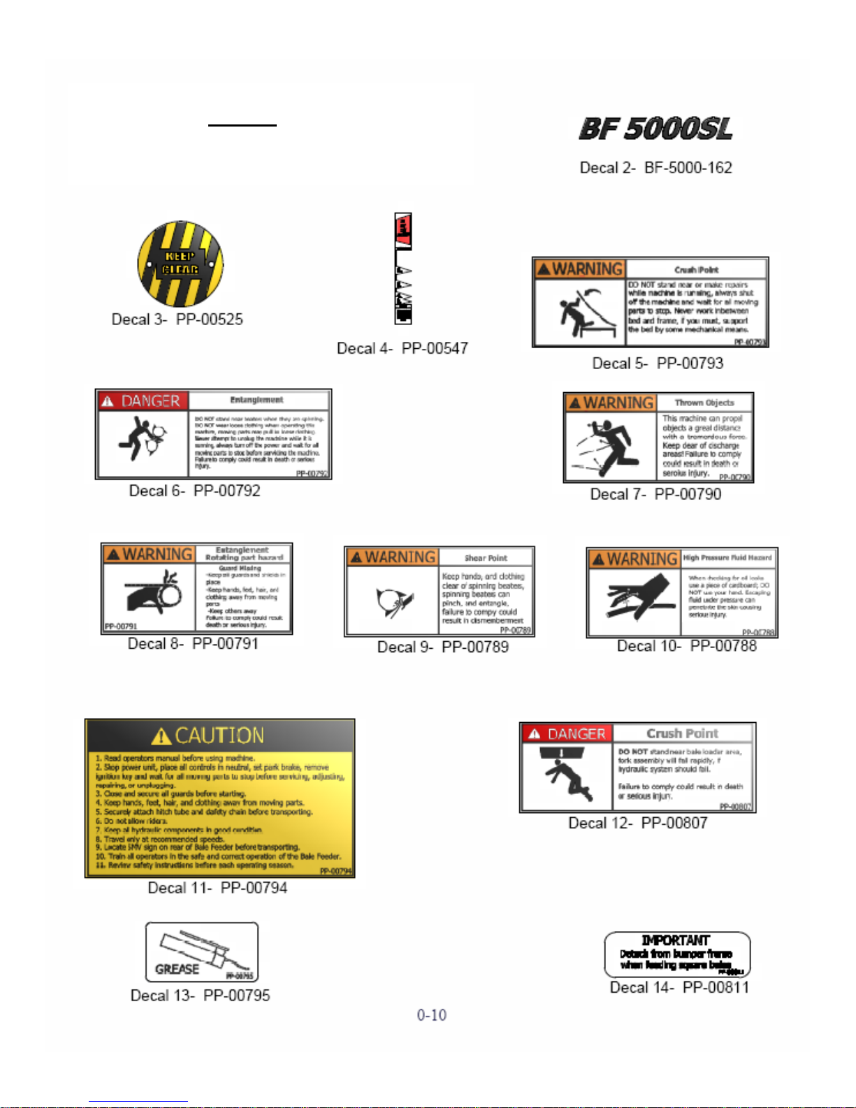
The following safety decals have been placed on your machine in the areas indicated. They
are intended for personal safety and or those working with you. Please take this manual and
walk around your machine to note the content and location of these warning sign. Review
these warning signs and the operating instruction detailed in this manual with your machine
operators. Keep the decals legible, if they are not, obtain replacements from your authorized
dealer. The decal replacement numbers are listed with each decal.
Decals
10
11
12
Decals

Item
Qty
Part #
Description
2
1
PP-00525
Keep Clear Decal
3
1
PP-00547
Lift Platform Decal
4
2
PP-00793
Crush Point (Warning) Decal
5
2
PP-00792
Entanglement (Danger) Decal
6
2
PP-00790
Thrown Objects Decal
7
2
PP-00791
Entanglement (Warning) Decal
8
2
PP-00789
Shear Point Decal
9
1
PP-00788
High Pressure Decal
10
1
PP-00794
Read Manual Decal
11
3
PP-00807
Crush Point (Danger) Decal
12
6
PP-00795
Grease Decal
13
2
PP-00811
Detach From Bumper Decal
Decals
13
14
Item
Qty
Part #
Description
2
1
BF-5000-a19
Second Roller
3
1
BF-5000-a20
Bumper Roller
4
2
BF-5000-260
Bumper Plate
5
2
PP-00655
F206, 1.125 (ID) Bearing
6
8
PP-00170
5/8-11, UNC Lock Nut
7
8
PP-00323
Gr.3, 5/8-11 x 1.75 Hex Cap Screw
8
8
PP-00332
7/16-14 UNC Lock Nut
9
4
PP-00192
USS Zinc Plated ¾ Flat Washer
10
8
PP-00636
Gr.3, 7/16-14 UNC x 1.5 Hex Cap Screw
11
4
PP-00003
¾-10 UNC Lock Nut
12
4
PP-00047
Gr.3, ¾-10 UNC x 2 Head Cap Screw
13
1
BF-5000-SL-00
Complete Assembly
Items you will find with your Tube-line Self Loading Bale Feeder
15
Self Loading Assembly
Item
Qty
Part #
Description
1
1
BF-5000-325
Cord Protector
2
1
BF-5000-SL-00
Frame Assembly
3
1
BF-5000-a01
Top Drum Assembly
4
1
BF-5000-a02
Bottom Drum Assembly
5
16
PP-00014
½-13 UNC Lock Nut
6
4
PP-00309
F207-22 Pillow Block
7
16
PP-00509
Gr.3, 1/2-13 UNC x 1.75 Hex Cap Screw
8
1
PP-00580
1/8” Galv. Braided Wire Cable (96”)

16
Self Loading Assembly
Item
Qty
Part #
Description
1
2
BF-5000-246
Chain Tightener Bracket
2
3
BF-5000-253
Key
3
1
BF-5000-254
60 series-28.5 Links
4
1
BF-5000-255
60 series-32 Links
5
2
BF-5000-a17
Slide Assembly
6
4
PP-00013
1/2-13 UNC Hex Nut
7
8
PP-00035
5/8 Flat Washer
8
2
PP-00060
60-15 Idler Sprocket
9
4
PP-00153
Gr.5 3/8-6 x 1 Hex Head Cap Screw
10
1
PP-00202
HMD Motor MLHPQ400C4B
11
1
PP-00420
60-15 X ID 1” Drive Sprocket
12
8
PP-00504
5/16-18 UNC x .5 Socket Head Set Screw
13
1
PP-00521
60-30 Drive Sprocket
14
1
PP-00522
60-42 Drive Sprocket
15
1
PP-00523
60-15 Drive Sprocket
16
2
PP-00589
Gr.3 5/8-11 UNC x 2 5/8 Hex Head Cap Screw

17
Item
Qty
Part #
Description
1
2
BF-5000-106
Tightener Rod
2
1
BF-5000-108
Bale Feeder Small Guard
3
1
BF-5000-109
Bale Feeder Large Guard
4
1
BF-5000-250
Bottom Tightener Rod
5
6
PP-00008
3/8 Flat Washer
6
6
PP-00026
3/8-16 Hex Nut
7
3
PP-00590
Hand Wheel
Self Loading Assembly

18
Self Loading Assembly
Item
Qty
Part #
Description
1
1
BF-5000-245
Hitch Bracket
2
1
BF-5000-SL-04
Front Hitch Support
3
1
BF-5000-SL-11
Hose Bracket
4
1
PP-00003
¾-10 UNC Lock Nut
5
1
PP-00007
3/8-16 UNC Lock Nut
6
2
PP-00014
½-13 UNC Lock Nut
7
4
PP-00108
¼-20 UNC Lock Nut
8
1
PP-00302
15’ Jack
9
2
PP-00423
Rope Pulley
10
2
PP-00499
Gr.3 ¼-20 UNC x 1.5
11
1
PP-00535
Manual Holder
12
2
PP-00560
Gr.3 ½-13 UNC x 5.5 Hex Head Cap Screw
13
1
PP-00561
Gr.3 ¾-10 UNC x 6 Hex Head Cap Screw
14
1
PP-00643
Gr.3 3/8-16 UNC x 1.25 Hex Head Cap Screw
15
2
PP-00654
Gr.3 ¼-20 UNC x 1.25

19
Self Loading Assembly
Item
Qty
Part #
Description
Item
Qty
Part #
Description
1
10
BF-5000-175
Weight
14
1
BF-5000-a13
Latch Pin Assembly
2
2
BF-5000-257
Spacer
15
1
CY-40019-01-00
4” Bore x 19” Stroke Cylinder
3
1
BF-5000-SL-01
Frame Assembly
16
3
PP-00008
3/8” Flat Washer
4
1
BF-5000-SL-02
Loader Arm Assembly
17
6
PP-00014
½-13 UNC Lock Nut
5
1
BF-5000-SL-03
Fork Frame Assembly
18
2
PP-00016
½ Flat Washer
6
1
BF-5000-SL-08
Arm Assembly
19
3
PP-00153
Gr.5 3/8-16 UNC x 1 Hex Head Cap Screw
7
1
BF-5000-SL-09
Top Loader Arm
20
4
PP-00310
Gr.3 ½-13 UNC x 2.5 Hex Cap Screw
8
1
BF-5000-SL-10
Loader Hook
21
2
PP-00321
Gr.3 ½-13 UNC x 1 Hex Head Cap Screw
9
1
BF-5000-a07
Fork Pin
22
4
PP-00546
Fork Spear (39”)
10
1
BF-5000-a08
Loader Arm Pin
23
2
PP-00557
Gr.3 ½-13 UNC x 5 Hex Head Cap Screw
11
1
BF-5000-a09
Top Loader Arm Pin
24
4
PP-00559
Gr.3 M30 x 3.5 Hex Nut
12
1
BF-5000-a11
Loader Cyl. Bottom Pin
25
1
PP-00648
Roll Pin
13
1
BF-5000-a12
Loader Cyl. Top Pin
1
SK40019
Cylinder Seal Kit

20
Self Loading Assembly
Item
Qty
Part #
Description
1
1
BF-5000-a03
Large Wiper Assembly
2
4
PP-00332
7/16-14 UNC Lock Nut
3
4
PP-00636
Gr.3 7/16-14 UNC x 1.5 Hex Cap Screw
4
2
PP-00637
7/16 Lock Washer
5
2
PP-00638
7/16 Washer

21
Self Loading Assembly
Item
Qty
Part #
Description
1
2
BF-5000-229
Bed Spacer
2
4
BF-5000-238
Bale Extension Pin
3
1
BF-5000-a06
Bed Assembly
4
1
BF-5000-a10
Bale Extension Assembly
5
1
BF-5000-a14
Bed Cyl. Pin Assembly
6
1
BF-5000-a15
Frame Cyl. Pin Assembly
7
1
CY-30014-01-00
3” Bore x 14” Stroke Cylinder
8
2
P-00298
Tire and Rim 11L 15
9
6
PP-00008
3/8 Flat Washer
10
4
PP-00014
½-13 UNC Lock Nut
11
3
PP-00108
¼-20 UNC Lock Nut
12
2
PP-00153
Gr.5 3/8-16 c 1 Hex Head Cap Screw
13
4
PP-00405
Hitch Pin Clip (.15 dia)
14
2
PP-00526
6000lbs Hub Assembly
15
4
PP-00560
Gr.3 ½-13 UNC x 6 Hex Head Cap Screw
16
1
PP-00566
Diverter Valve
17
3
PP-00651
Gr.3 1/4=-20 UNC x 2.25
1
SK30014
Cylinder Seal Kit

22
Self Loading Assembly
Item
Qty
Part #
Description
1
1
BF-5000-a06
Bed
2
1
PP-00516
Plastic Bed
3
1
BF-5000-a16
Stop Pad Assembly

23
Self Loading Assembly
Item
Qty
Part #
Description
1
2
BF-5000-239
Fork Bushing
2
2
BF-5000-240
Arm Pivot Bushing
3
1
BF-5000-269
Cable Spacer
4
1
BF-5000-SL-02
Loader Arm Assembly
5
1
PP-00108
¼-20 UNC Lock Nut
6
3
PP-00227
¼ USS Zinc Plated Flat Washer
7
1
PP-00499
Gr.3 ¼-20 x 1.5
8
2
PP-00565
Knock in Greaser

24
Self Loading Assembly
Item
Qty
Part #
Description
1
1
BF-5000-SL-08
Arm Assembly
2
2
BF-5000-241
Loader Arm Bushing
3
2
PP-00565
Knock in Greaser
4
1
BF-5000-242
Latch Bushing

25
Self Loading Assembly
Item
Qty
Part #
Description
1
1
BF-5000-SL-09
Top Loader arm
2
2
BF-5000-243
Small Loader Arm Bushing
3
2
PP-00565
Knock in Greaser
4
2
BF-5000-244
Large Loader Arm Bushing

26
Indicator Assembly
BF-5000-SL-05
Item
Qty
Part #
Description
1
1
BF-5000-182
Indicator
2
1
BF-5000-183
Indicator Slider
3
1
BF-5000-SL-06
Indicator Assembly aa
4
1
BF-5000-SL-07
Indicator Assembly bb
5
2
PP-00108
¼-20 UNC Lock Nut
6
2
PP-00352
Gr.3 ¼-20 UNC x 1 Hex Cap Screw
7
1
PP-00491
Spring
8
1
PP-00547
Decal - Lift Platform

27
Wiper Assembly
Item
Qty
Part #
Description
1
10
BF-5000-100
Slot Opening Guide
2
5
BF-5000-101
Inside Bracket Guide
3
1
BF-5000-a18
Small Wiper Assembly
4
30
PP-00005
Gr.3 5/16-18 UNC x .75 Hex Head Cap Screw
5
30
PP-00006
5/16 Flat Washer
6
30
PP-00080
5/16-18 Lock Nut

28
Bumper Assembly
Item
Qty
Part #
Description
1
2
BF-5000-260
Bumper Plate
2
1
BF-5000-a19
Second Roller
3
1
BF-5000-a20
Bumper Roller
4
4
PP-00003
¾-10 UNC Lock Nut
5
4
PP-00047
Gr.3 ¾-10 UNC x 2 Hex Head Cap Screw
6
8
PP-00170
5/8-11 UNC Lock Nut
7
4
PP-000192
USS Zinc Plated 3/4 Flat Washer
8
8
PP-00323
Gr.3 5/8-11 UNC x 1.75 Hex Cap Screw
9
8
PP-00332
716-14 UNC Lock Nut
10
8
PP-00636
Gr.3 7/16-14 UNC x 1.5 Hex Cap Screw
11
2
PP-00655
F206 1.125 (ID) Bearing

29
6000lb Hub Assembly
Item
Qty
Part #
Description
1
1
PP-00025
1-UNC Castle Nut
2
1
PP-00028
3/16 x 2 Brass Cotter Pin
3
1
PP-00030
1 Flat Washer
4
6
PP-00031
9/16-18 UNF x 1.75 Wheel Stud
5
1
PP-00527
6000lbs Hub
6
1
PP-00528
D-6000 Dust Cap
7
1
PP-00529
Grease Seal cr20148
8
1
PP-00530
Inner Cone
9
1
PP-00531
Outer Cone
10
1
PP-00532
Outer Cup
11
1
PP-00533
Inner Cup

30
Hydraulic Set-up

31
Item
Qty
Part #
Description
1
1
CY-30014-01-00
Cylinder 3 x 14
2
1
CY-40019-01-00
Cylinder 4 x 19
3
1
PP-00104
Adapter #8 M-ORB/#6 M-JIC
4
1
PP-00166
Adapter #6 M-JIC/#6-NPT
5
1
PP-00202
Hydraulic Motor
6
2
PP-00410
Adapter #* M-JIC/ #10 M-ORB
7
1
PP-00511
Tee #6 F-NPT/#6 F-NPT
8
1
PP-00566
Diverter Valve
9
2
PP-00656
Adapter 90 #8 M-JIC/#8 M-ORB
11
4
PP-00662
Adapter #6 M-JIC/#8 M-NPT
12
4
PP-00661
Pioneer Male Coupler #8 F-NPT
Hydraulic Set-up

32

33
Section 2
General Information
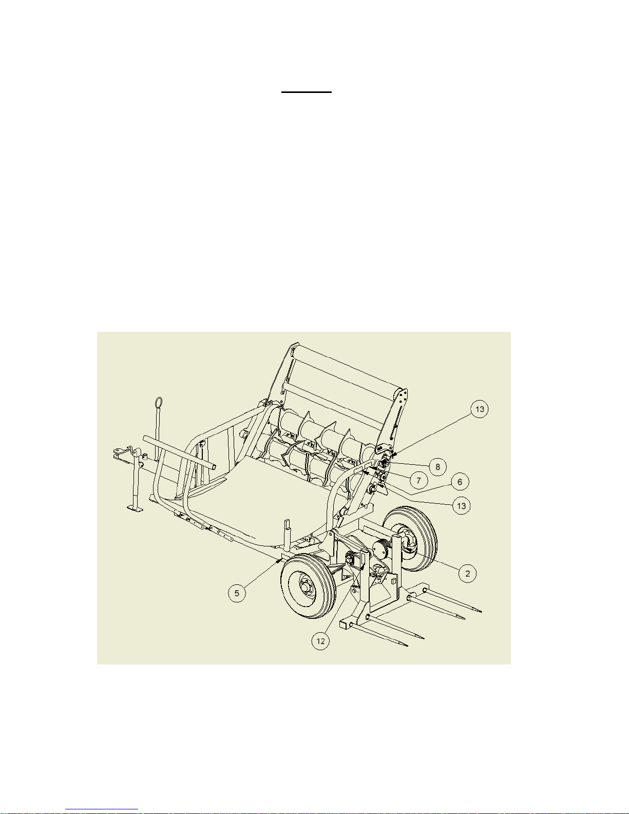
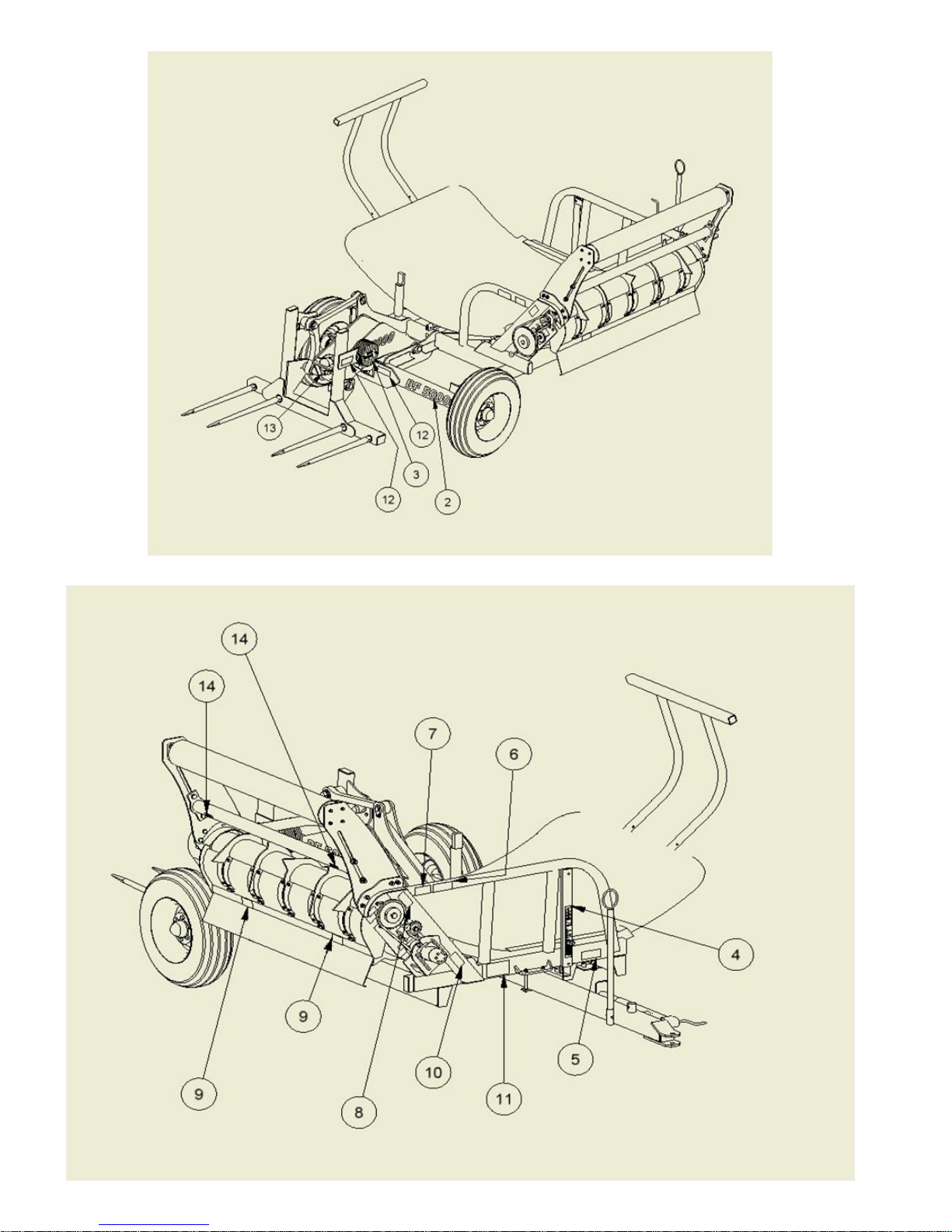
Self Loading Bale Feeder
The Self Loading Bale Feeder unit consists of the main components listed below. The
bale Feeder is powered by hydraulic pressure from a tractor. The hydraulic pressure from
a tractor powers the hydraulic motor as well as both lift cylinders.
Principle Components
1. Frame
2. Beaters
3. Bed
4. Beater Motor
5. Bed Cylinder
6. Loader Arm Assembly
7. Fork Frame Assembly
8. Indicator
Section 1
Assembly Information
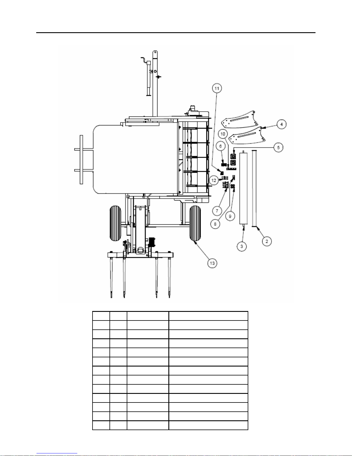
NOTE: Assembly drawings are intended
for use of replacement parts only, and not
as assembly guide.
NOTE: Assembly drawings are placed in
sequential order, as one would assemble, if
desired part on drawing is shown already
assembled you have gone to far, and must
look at a previous drawing.

34
Self Loading Bale Feeder Terminology
Serial# XX BFSL XXX
XX = year manufactured
BFSL = product identification
XXX = sequential numbering
Model # BF5000SL
BF5000 = BF5000
SL = Self Loading unit
Capacity
2 Bales = this unit can only
contain 2 bales.
Weight
2700 = weight in pounds
Product Identification
The P.S.N stamped on the metal tag(1), is located on the front of the bale feeder.

35
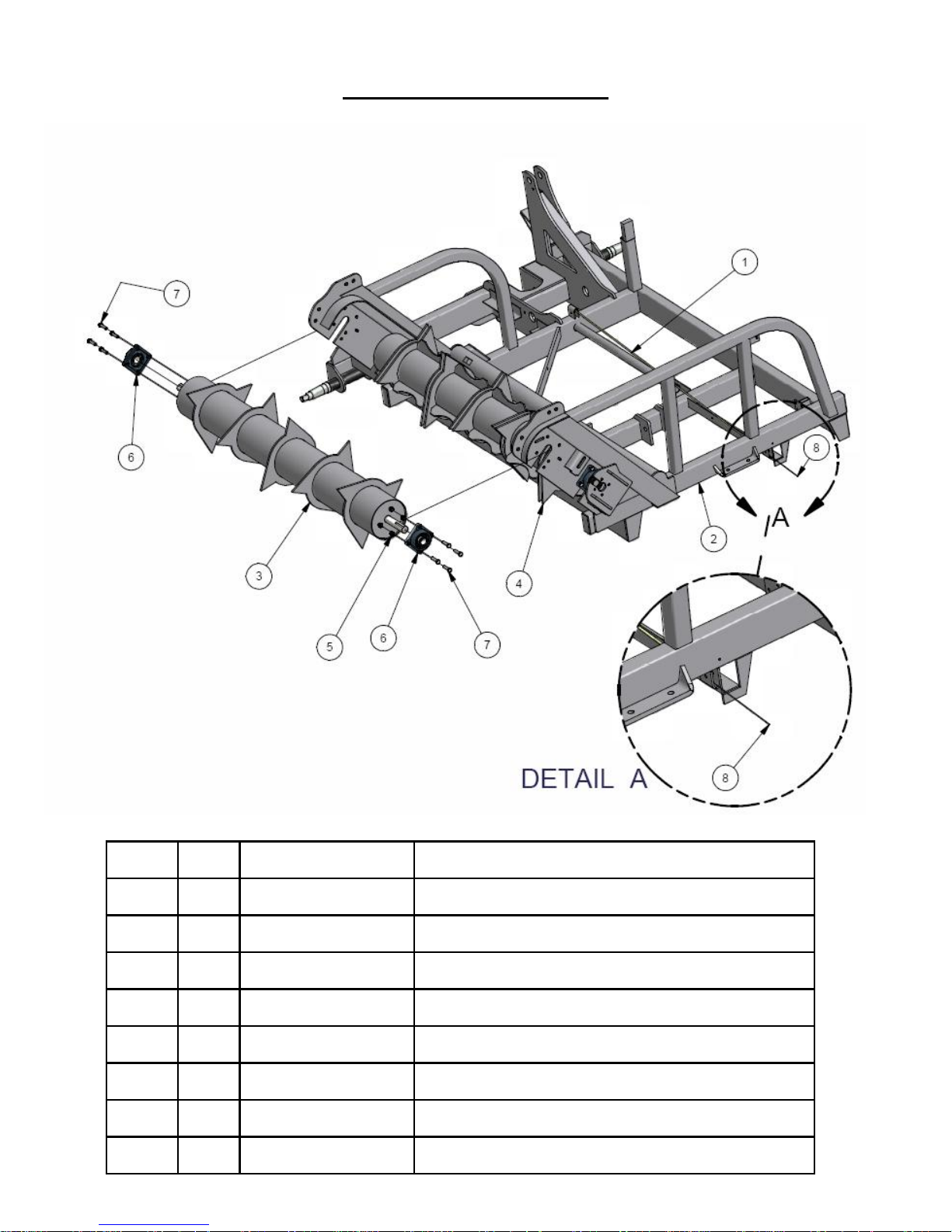
When you first receive the Tube-line Bale
Feeder you will need to install the bumper bale
rollers
1. Secure bumper plate (1), using six 5/8-11
bolts(3), with 5/8-10 nuts(2) to the Tube-line
Bale Feeder.
2. Secure second roller(5), with ¾-10 bolts(2),
¾ flat washer(3) and ¾-10 hex nut(3) to
bumper plate(1).
3. Secure bearing(4), and bumper roller(2),
with 7/16-14 bolts(3), 7/16-14 hex nuts(5) to
bumper plate (1).
Initial Setup

36
Adjusting the BF5000 Beater Guide
1. Loosen 5/16-18 bolt (1), and 5/16-18 nuts.
2. Adjust slot opening guide to 1/16” from
beater and retighten fasteners.

37
1. Reverse tractor and align drawbar hole with
BF5000 and insert pin.
2. Release jack(1), and secure in place(2).
3. Connect hydraulic lines.
4. Do a complete walk-around visual check to
be sure there are no loose parts or
components.
5. Do a visual check of all hoses to make sure
they are securely tied so they will not pinch
or drag during transporting.
WARNING
Make sure to apply the park brake before
leaving the tractor. Death or serious injury
could result if tractor moves.
Tube-line Bale Feeder Hook Up
Check the hitch pins and safety chain periodically to make sure they are secure.

38
1. Transport the Tube-line Bale Feeder with the
SMV(Slow Moving Vehicle) sign, displayed
at the rear of the Tube-line Bale Feeder and
use your hazard lights if the law permits.
Check local road laws before transporting.
2. When transporting the Tube-line Bale
Feeder on the road be aware of the width
length of the Bale Feeder especially while
carrying a square bale.
3. Do not transport the machine at night, at
dawn, or at dusk.
4. Do not exceed 32kph (20mph) during
transport.
Transport Safety

39
Section 3 Operation
Keep bystanders away from the machine.
Failure to comply could result in death or
serious injury.
WARNING
NOTE: Setup instructions assume the operator
already has read and has the Tube-line Bale
Feeder attached to the tractor.
1. Apply hydraulic pressure.
2. Raise and lower bed.
3. Raise and lower bale
loading assembly.
Engage the parking brake on the tractor, shut
the engine down, and wait for all moving parts
to stop before leaving the cab. Failure to
comply could result in death or serious injury
WARNING
4. Check for loose or missing nuts and bolts.
Tighten any that are loose and replace any
missing fasteners.
5. Make sure that all protective shields are in
place and properly secured.
6. Check all hydraulic hoses and fittings to be
sure they are tight and that no hose damage
has occurred during mounting. Repair or
replace any damaged parts before starting
the machine.
Do not run with defective hoses or
fittings. Make sure that there is no
pressure in the hydraulic lines before
checking or repairing. High-pressured
hydraulics can cause death or serious
injury.
7. Restart the Tube-line Bale Feeder.
WARNING

40
Loading Bales (Wrapped Bales)
1. With rear fork assembly down reverse the
unit and pierce bale.
2. Apply hydraulic pressure and lift the bale
until it is approximately 4” above plastic bed.
3. Remove plastic wrap and net wrap.
4. Lower bale onto Tube-line Bale Feeder bed
and release fork rack and lower into loading
position.
5. Once again pierce the bale and lift the bale a
few inches off the ground.

41
Section 4
Lubrication
Introduction
This section gives full details of the
procedures necessary to maintain the Tube-line
Bale Feeder at peak efficiency. Complete all
checks and services in this section at the hour
interval shown.
Important: Failure to complete the required
maintenance at the intervals shown can
cause unnecessary downtime.
The recommended lubrication intervals are
for average conditions. Perform lubrication
more often when operating under
adverse conditions.
Before lubricating the Tube-line
Bale Feeder, always
observe the following precautions:
•Turn off tractor, set parking brake,
remove key and wait for all moving
parts to stop before leaving cab.
Failure to comply could result in
death or serious injury.
WARNING

42
Linkage Assembly (3)
Apply 3 strokes of grease every 25 hours at
point (3) (4 locations).
Loader Arm Assembly (1)
Apply 3 strokes of grease every 25 hours at
point (1) (2 locations).
Beater Bearing (2)
Apply 3 strokes of grease every 50 hours at
point (2) (4 locations).
Cylinder Pivot (4)
Apply 3 strokes of grease every 50 hours at
point (4) (4 locations).
Hub (5)
Apply 3 strokes of grease every 50 hours at
point (5) (2 locations).
Bumper Bearing (6)
Apply 3 strokes of grease every 50 hours at
point (6) (2 locations)

43
Section 5
Maintenance
Complete all checks and services in this section at the hour interval shown.
IMPORTANT: Failure to complete the required maintenance at intervals shown can cause
unnecessary downtime.
The recommended intervals are for average conditions. Perform maintenance more often
when operating the Tube-line BF5000 under adverse conditions.
Before performing any adjustments or maintenance on the Tube-line
BF5000, observe these safety precautions:
•Turn off tractor, set parking brake, remove key and wait for all moving
parts to stop before leaving cab.
Failure to comply could result in death or serious injury.
WARNING
Careful inspection and service of the BF5000 prior to
operation each day will prevent needless breakdowns and
delays in the field. Make the following checks and
adjustments.
Be alert for loose hardware and tighten
or replace as required.
Lubricate the Tube-line BF5000
according to the instructions in the
“Lubrication” section of this manual.
Under adverse conditions, shorten the
lubrication intervals.
Daily Maintenance
Preseason Service
Prior to beginning the harvest after offseason
storage, take the following steps be certain the
Tube-line BF5000 is in good condition.
Check slot opening guide, make sure it is tight
and that the beater blade clears as described in
the “General Information” section.
Lubricate the Tube-line BF5000 according to the
“Lubrication” section of this manual.
Tighten or replace any damaged or missing
fasteners.
End of Season Service
Prior to storing the Tube-line BF5000
during the off season, follow these steps
to ensure easier preparation for the next
season and longer Tube-line BF5000
life
Pack all grease point with grease (see
the “Lubrication” section for grease
points location).
Remove all crop material from the
BF5000.

44
Section 6
Trouble Shooting
Problem: Several biscuits coming out at once.
Suggested remedy: The bed is too high. Lower the bed. The crop material was baled
when wet, reverse beaters 2 turns then forward again.
Round bales
Problem: The rotors turn, but the bale refuses to turn.
Suggested remedy: The platform is not raised high enough. The bale must be pushed
against both beaters.(see pg 3-2)
Problem: Crop material jams between top beater and wiper.
Suggested remedy: The wiper guides may need adjusting. (see pg 2-3)
General
Problem: The bale is dropping too hard onto platform.
Suggested Remedy: Spear bale lower when loading
Problem: Spear frame does not trip before the bale rests on the platform.
Suggested Remedy: Spear bale higher when loading

45
Section 7
Optional Equipment
Bale Extension
The bale extension, available as on option is
used primarily to contain square bales placed
on the bed of the Tube-line BF5000.
The bale extension is designed to contain the
biscuits of crop material placed on the bed of
the Tube-line BF5000, allowing the bale to be
feed and no crop material to spill off the non
feeding side.
Square Bale Extension
Slide bale extension assembly(1) into bed
extension receiver(2).
Secure bale extension with bale extension
pin(3), and hitch pin clip(4).

46

47

48
 Loading...