

Page 1
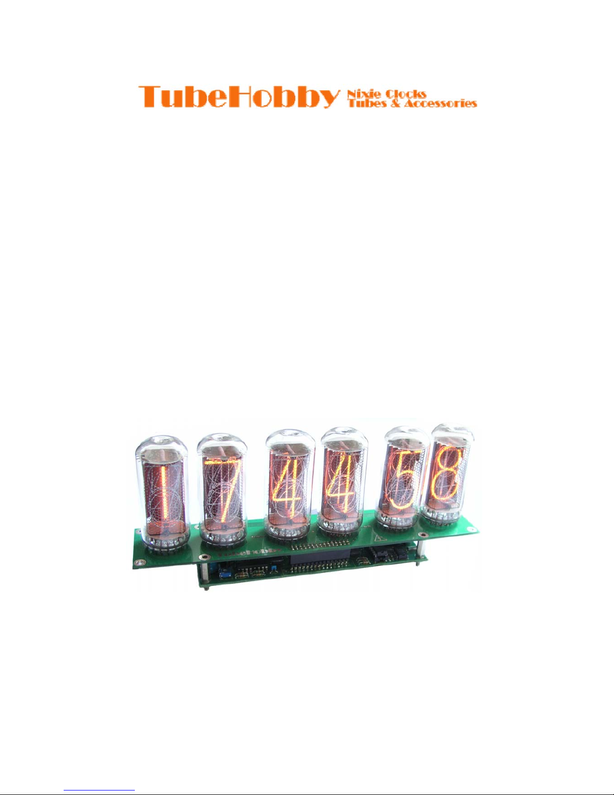
NCV2.1 Nixie Clock
User's guide
Firmware version: v1.3
Page 2
1 Safety instructions
Nixie clock is an electr ical device and cautious handling must be assured. In spite of the relatively
low voltage board power supply, a high voltage is present onboard. It can generate voltages
exceeding 200V and can cause electrical shock if handled inappr opriately. Keep in mind that nixie
tubes may be disa bled during night time but the clock can wake up at any time. Therefore do not
touch any component or soldering point when power is on. Safe assembling, connecting and
operation of this clock are the users’ responsibility. Keep the clock away from children.
The NCV2.1 nixie clock's circuits and software (firmware) may not be reverse engineered, copied
or used commercially without written permission.
2 Assembling
2.1 Logic board assembling
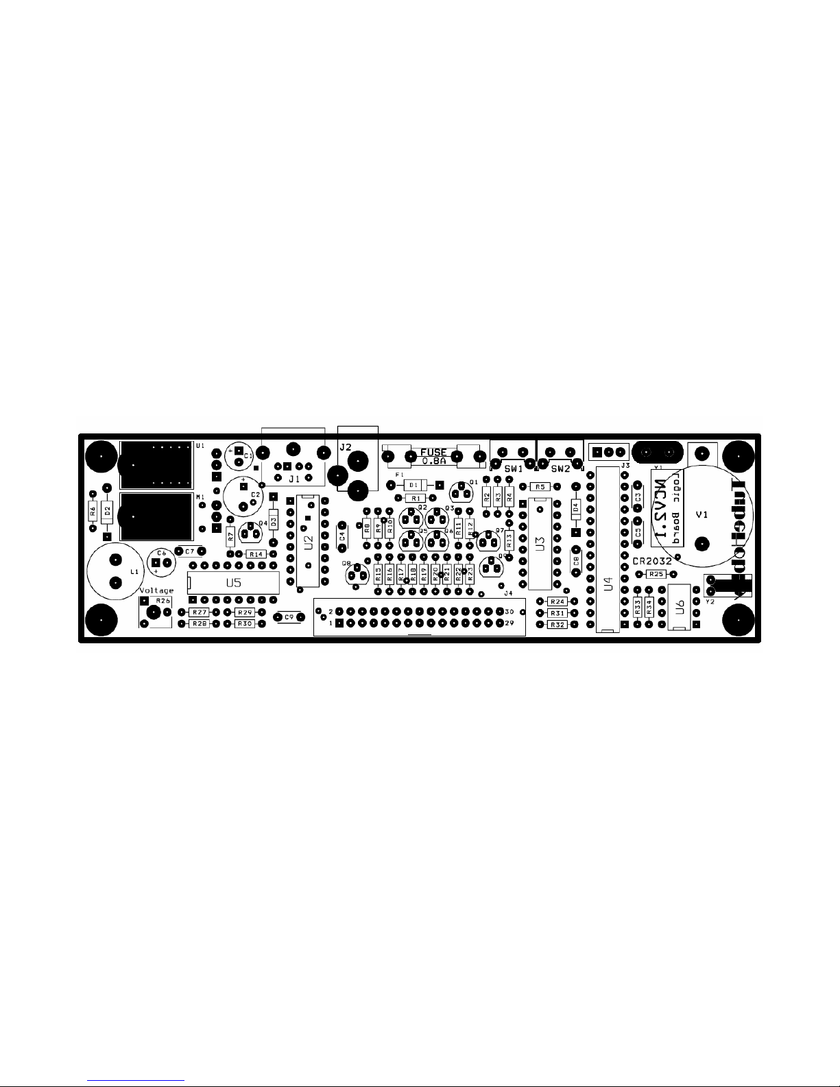
Start by fitting 0,25W resistors since they're the lowest. Then fit the diodes. Double check the
polarity of any polarity sensitive device before soldering. Then assembly all other components
height wise. If you want to experiment with your board or upgrade PICmicro with a newer firmware
in the future, you may consider to use the sockets for the ICs (sockets are optional and are not
provided along with kit. You may obtain them in your local store).
Do not use solder with acid, instead use colophony or any other not electrical conductive solder
resin. Set the soldering iron at a ppropriate temperature to avoid “cold soldering”. Do not heat any
point for more than 3 seconds, otherwise you risk to da mage the electronic components and printed
circuit board.
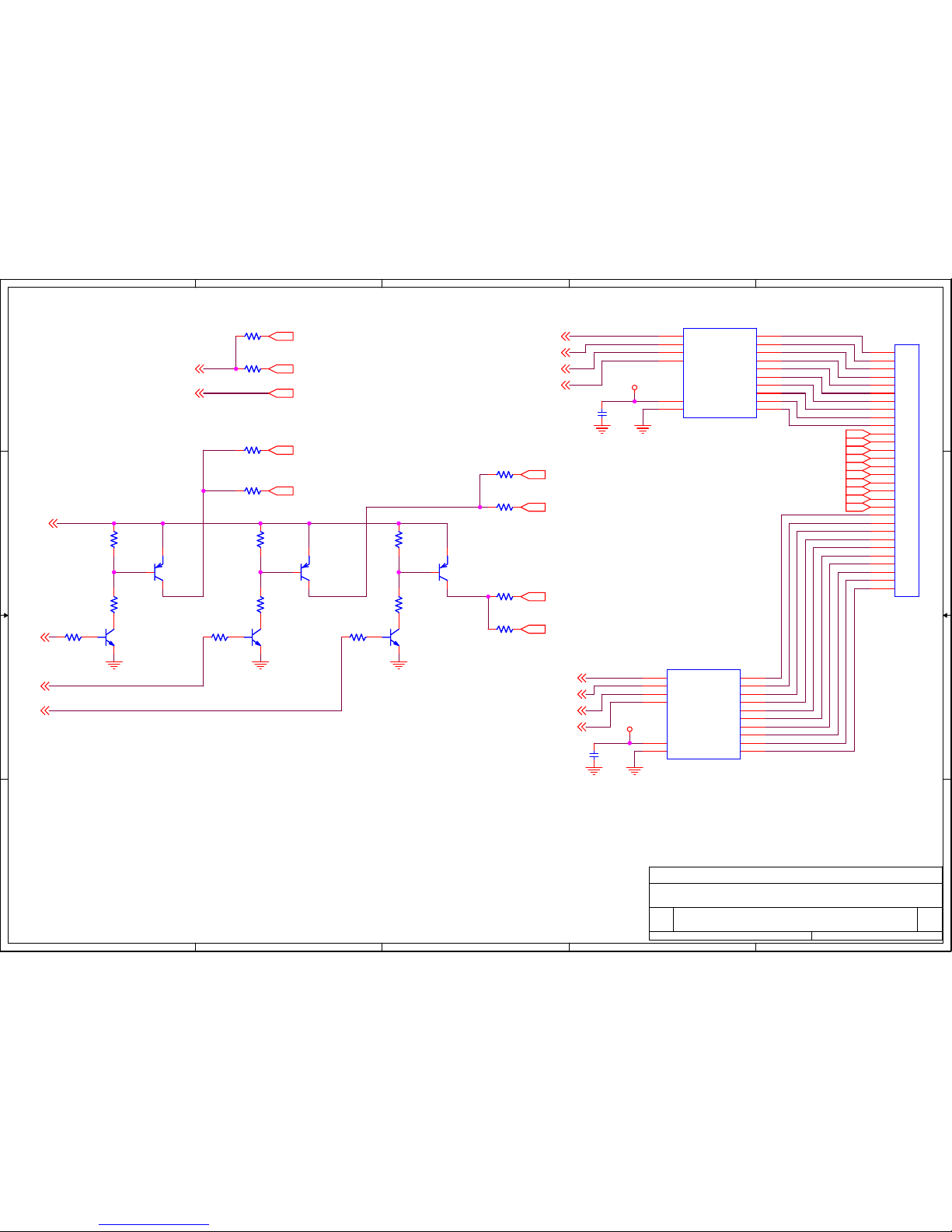
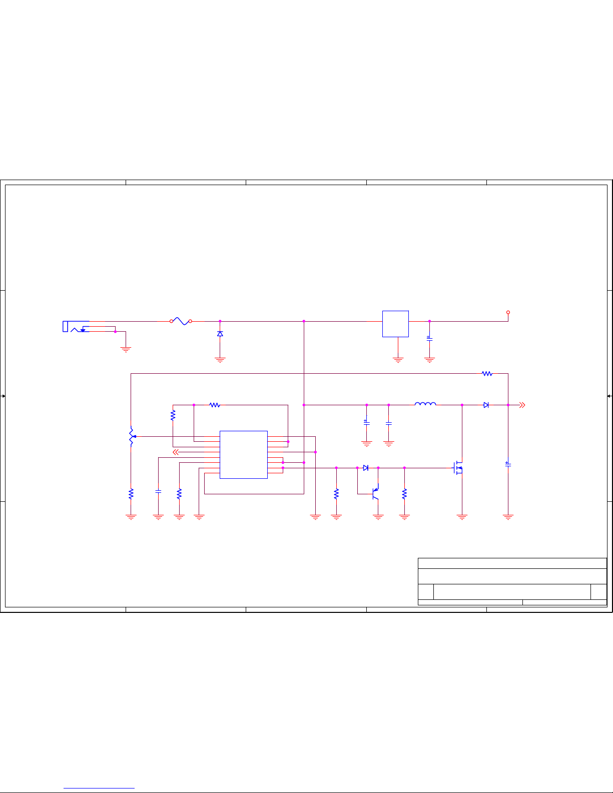
After successful assembly set high voltage using R26 trimmer, measure the voltage across C6
capacitor. Set the voltage to 160V for IN-14 nixie tubes and 170V for IN-18 nixie tubes. Check
power supply temperature after 10 minutes of operate, if switching transistor (M1 – IRF640) and/or
inductor are very hot set lower voltage.
For IN-18 tube's board, 2.2K anode resistors (R15, R17, R18, R19, R20, R21) should be used.
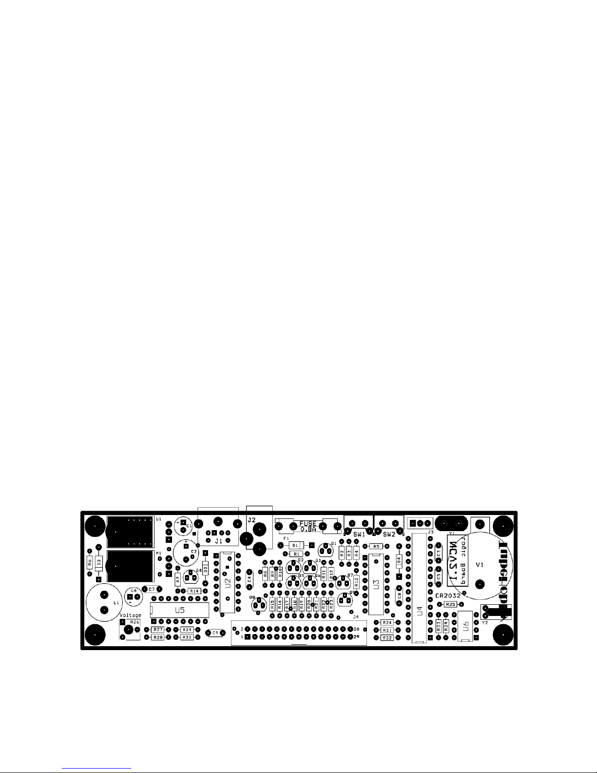
Fig. 1. The logic board's silk screen layer
Page 3
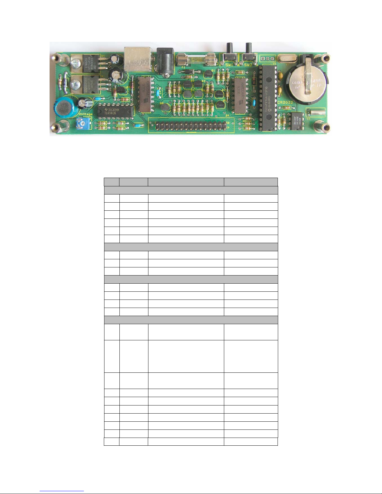
Fig. 2. Logic board
Table 1. Logic board's part's list.
Item Quantity Reference Part
Capacitors
1 1 C1 10U
2 1 C2 470U
3 2 C3, C5 22P
4 3 C4, C8, C9 10N
5 1 C6 1U 250V
6 1 C7 330N
Diodes
7 1 D1 1N4007
8 1 D2 UF4007
9 2 D3, D4 1N4148
Transistors
10 1 M1 IRF640
11 5 Q1, Q2, Q3, Q7, Q9 MPSA42
12 1 Q4 2SA1266
13 3 Q5, Q6, Q8 MPSA92
Resistors
14* 6
R15, R17, R18, R19, R20,
R21
2.2K
14* 18
R1, R3, R4, R5, R13, R15,
R17, R18, R19, R20, R21,
R24, R25, R28, R31, R32,
R33, R34
10K
15 7
R2, R8, R9, R12, R16,
R22, R27
100K
16 1 R6 910K
17 1 R7 220
18 3 R10, R11, R23 470K
19 1 R14 1K
20 1 R26 22K Trimmer
21 1 R29 5.6K
22 1 R30 15K
Page 4
Integrated circuits
23 1 U1 L7805CV
24 2 U2, U3 K155ID1
25 1 U4 PIC16F876A
26 1 U5 TL494
27 1 U6 DS1307
Other components
28 1 V1
CR2032
3V Lithium
Battery
29 1 Y1 Crystal 20MHZ
30 1 Y2
Crystal
32.768KHz
31 2 SW1, SW2
SW
PUSHBUTTON
32 1 L1 270UH
33 1 F1 FUSE 0.8A
34 1 J1 PS/2 Connector
35 1 J2 PWR Connector
36 1 V1 Battery holder
37 1 J4 30Pin Connector
38 2 F1 Fuse holder
39 2 - M3 Nut
40 10 - M3 Screw
41 4 - 20mm spacer
*2.2K resistors are provided along with the kit for IN-18 tubes instead of appropriate amount of 10K resistors.
2.2 Tube's board assembling
2.2.1 IN-14 board
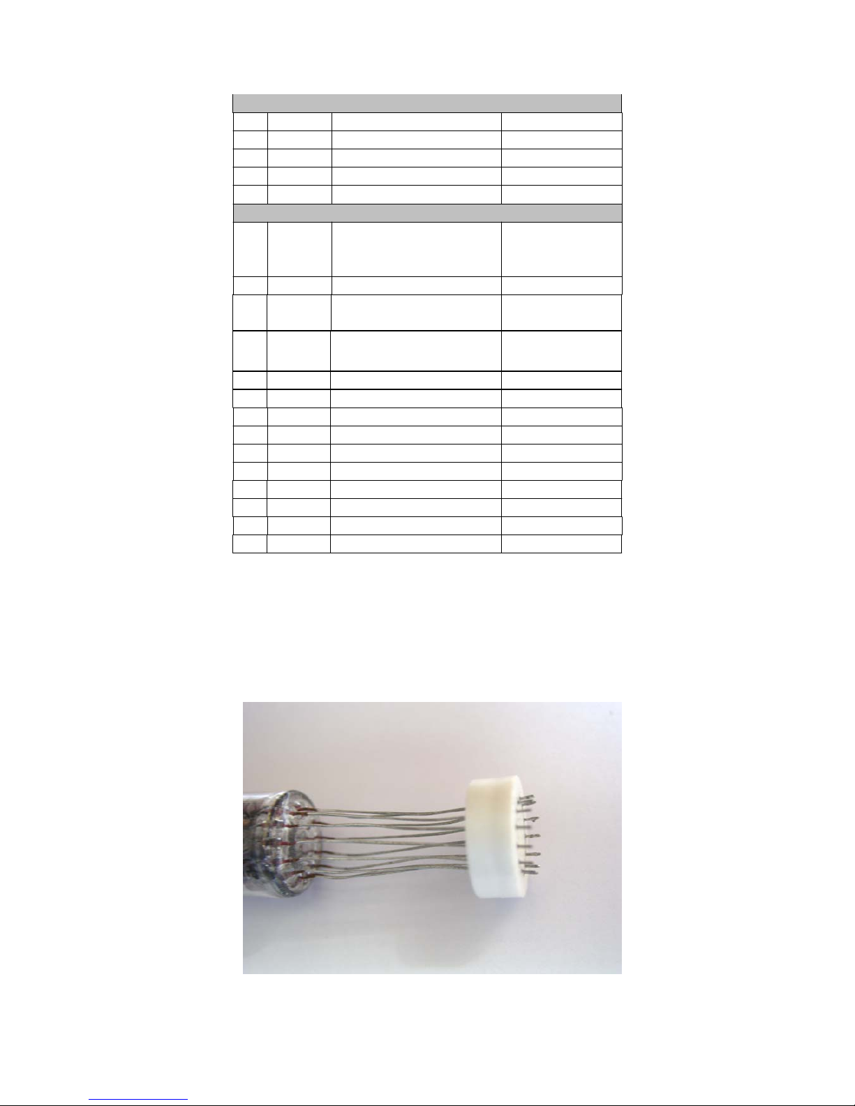
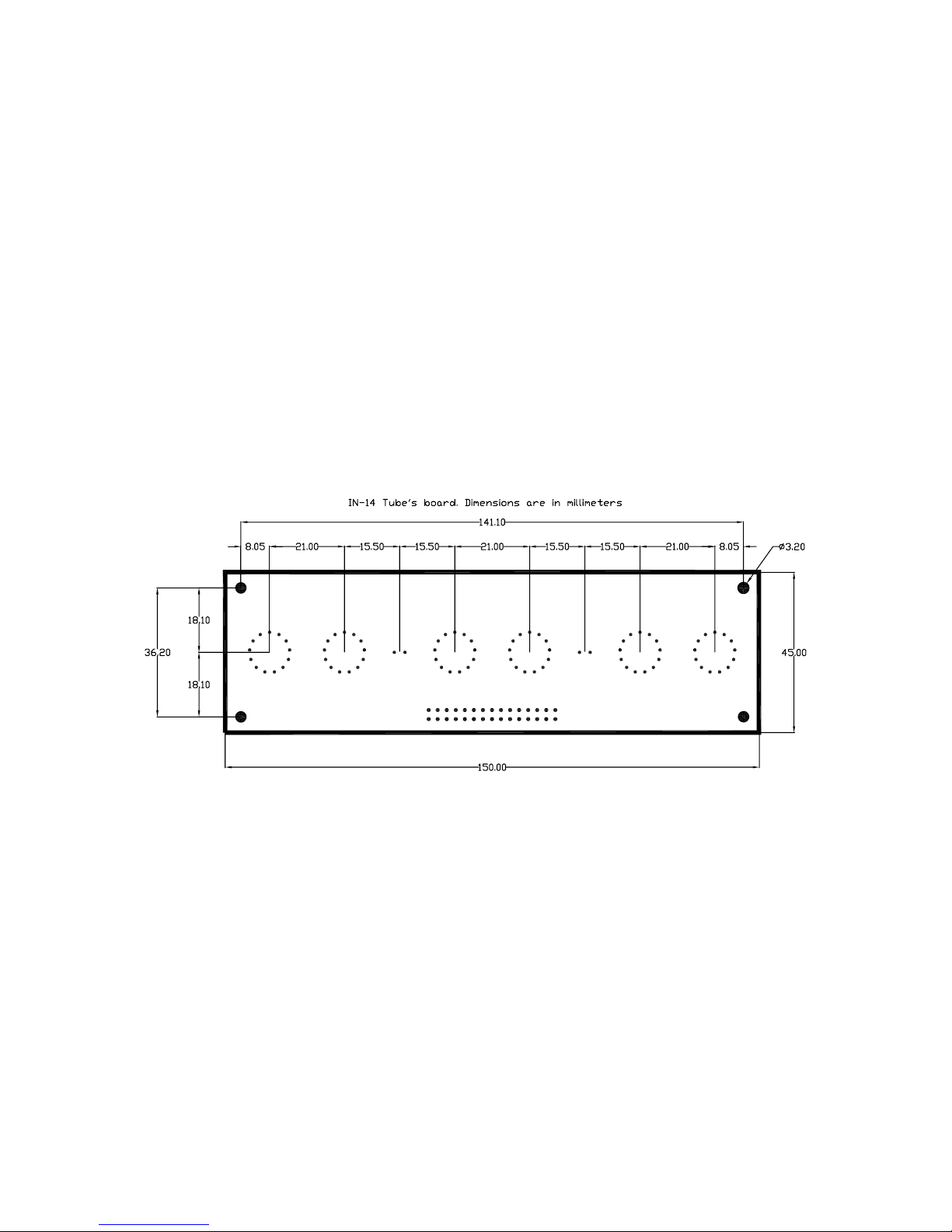
Move the plastic holder of the tube leaving approx 1-2mm of wire below the holder (see fig. 3) Be
careful not to move it away.
Fig. 3. Plastic holder
Page 5
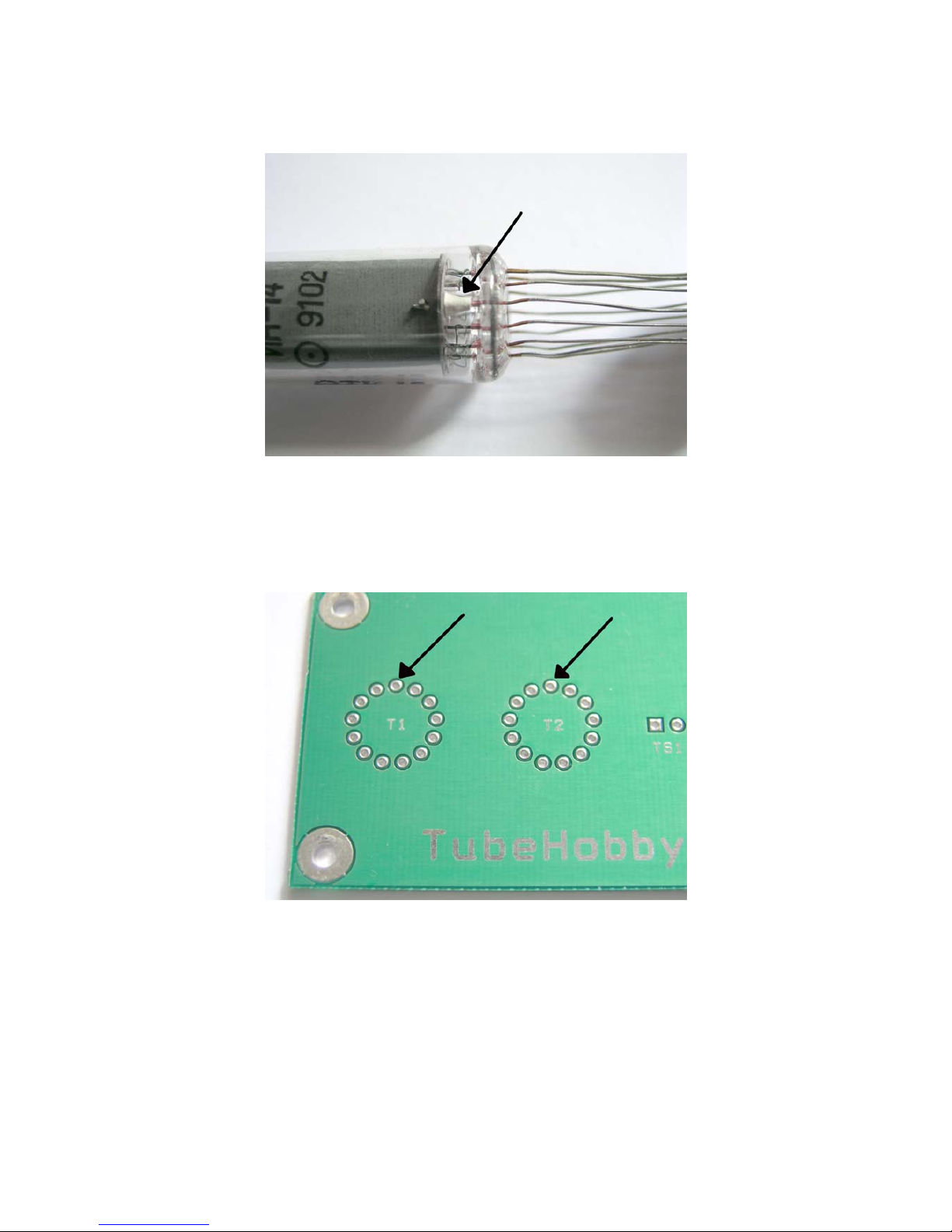
Find #1 pin of the tube. It is covered by the white substance inside the tube.
Fig. 4. Pin #1
Pin #1 on the PCB is the most upper pin.
Fig. 5. Pin #1 on PCB
Page 6
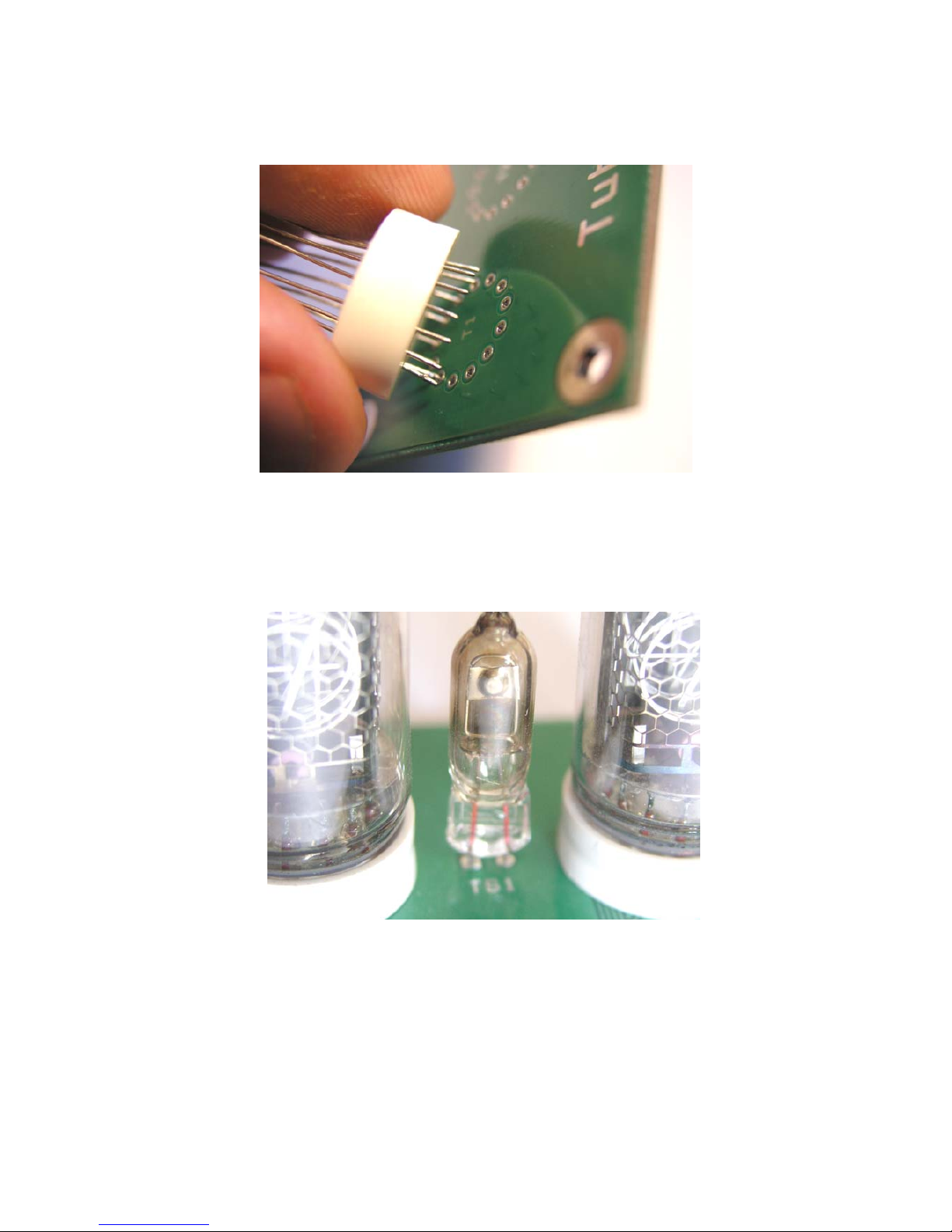
Insert the wires into the holes. Start from Pin #1. Be sure that the tubes are stacked on the right side
of the PCB.
Fig. 6. Tube assembling
Stack and solder all the tubes in the same way. Then fit the female 30-pin connector on the opposite
side of the PCB. Fit the column separator bulbs if you prefer to have them.
Fig. 7. IN-3 type column separator bulb
If IN-3 type column separator bulbs are used, be sure that they are stacked in the right polarity.
Page 7
2.2.2 IN-18 board
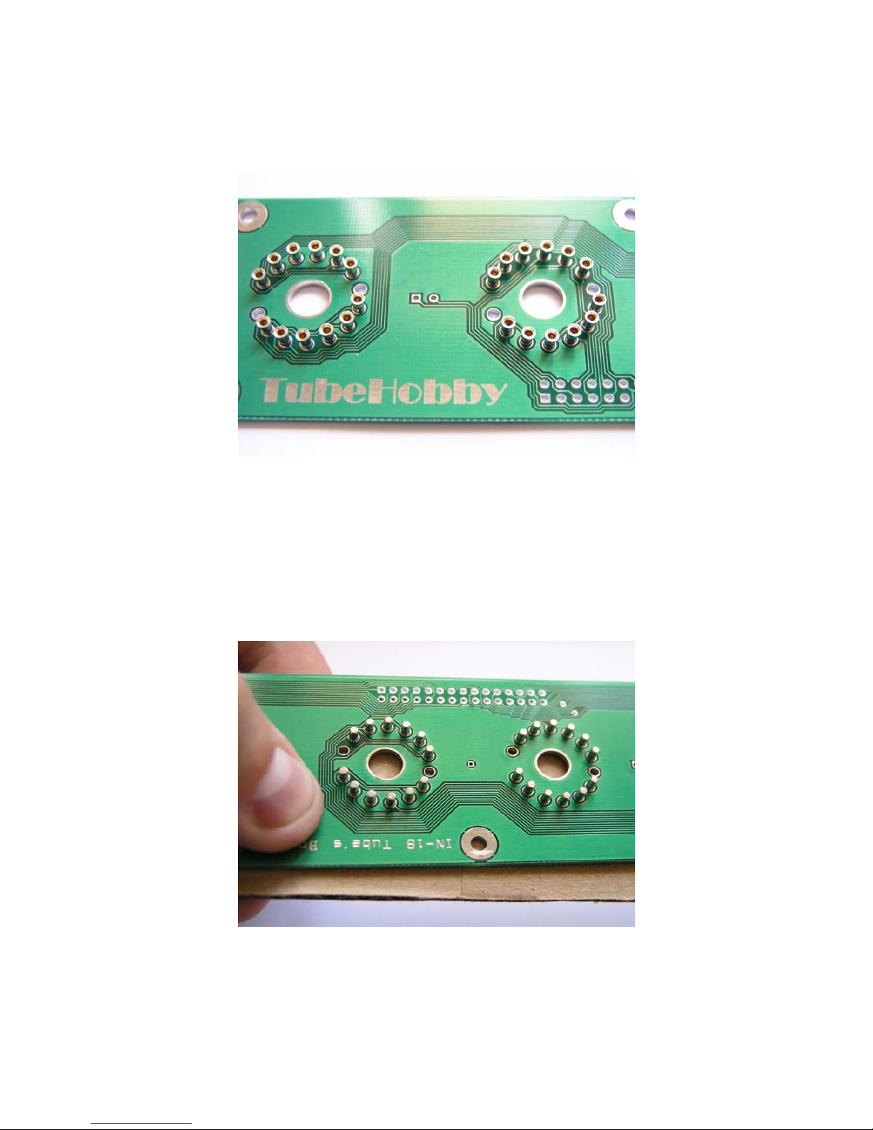
Put all 72 receptacles into the tube's board holes.
Fig. 8. Fitting receptacles
Note: pin #1 and pin #8 of each tube do not require receptacles since these pins ar e not connected.
Make sure that receptacles are fitted on the right side of the PCB.
After all receptacles are placed correctly, cover the board with a piece of hard paper and turn
everything upside-down.
Fig. 9. Turning over
Page 8
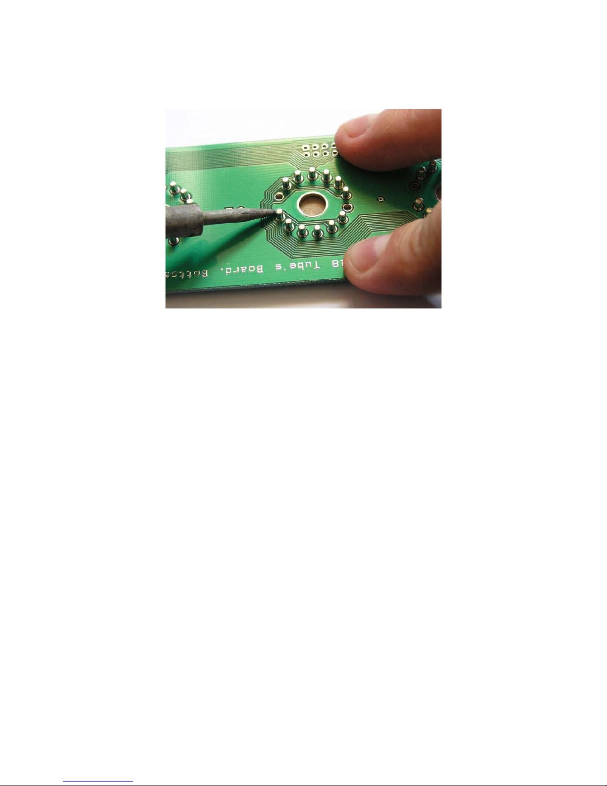
While soldering keep the PCB slightly pressed to ensure firm sitting of the rece ptacles. Do not use
too much solder.
Fig. 10. Soldering
Fit the female 30 pin socket on the bottom side. Fit the column separator bulbs if you prefer to have
them.
Page 9

3 Software
The clock's firmware is driven by operating system and is able to work in multitasking mode.
Several industrial protocols are involved and dozens of tasks and algorithms are coded. It is quite
complex and contains many thousands of code lines.
It is programmed so that all settings and tube's lifetime counter values are stor ed in the battery back
upped memory and are kept safely during the power outage. Moreover, time and date are still
counted when the clock has no power.
3.1 Firmware updates
Current version of firmware: v1.3
Added selection of new DST rules for USA and Canada.
Obsolete version v1.2.
Description of fixed bug: While DST months a re set (state 14 and 18) the month values are written
to incorrect places in memory. Therefore both customized vernal and autumnal month values stay
actual while clock has power s upply but can not be read properly after power outage. Both of them
will be set to default values (vernal = march; autumnal = october) after power outage.
Obsolete version v1.1.
Description of fixed bug: When power supply is connected DST offset is not calculated
immediately but is calculated on the first change of minute.
Obsolete version v1.0
First version of firmware.
NOTE: In order to update the firmware of your clock please send the PICmicro chip or whole logic
board back to us for re-flashing, or order preprogrammed chip. Please contact us by email:
3.2 Clock’s menu
NCV2.1 nixie clock has 2 pushbuttons. There are 4 different behaviors pushing them: short and
long push for each button. Long push event will be performed when the button is pressed for 3 or
more seconds.
Fig. 11. Menu transitions
SW1 short push
SW2 long push
SW2 short push
SW1 long push
Page 10
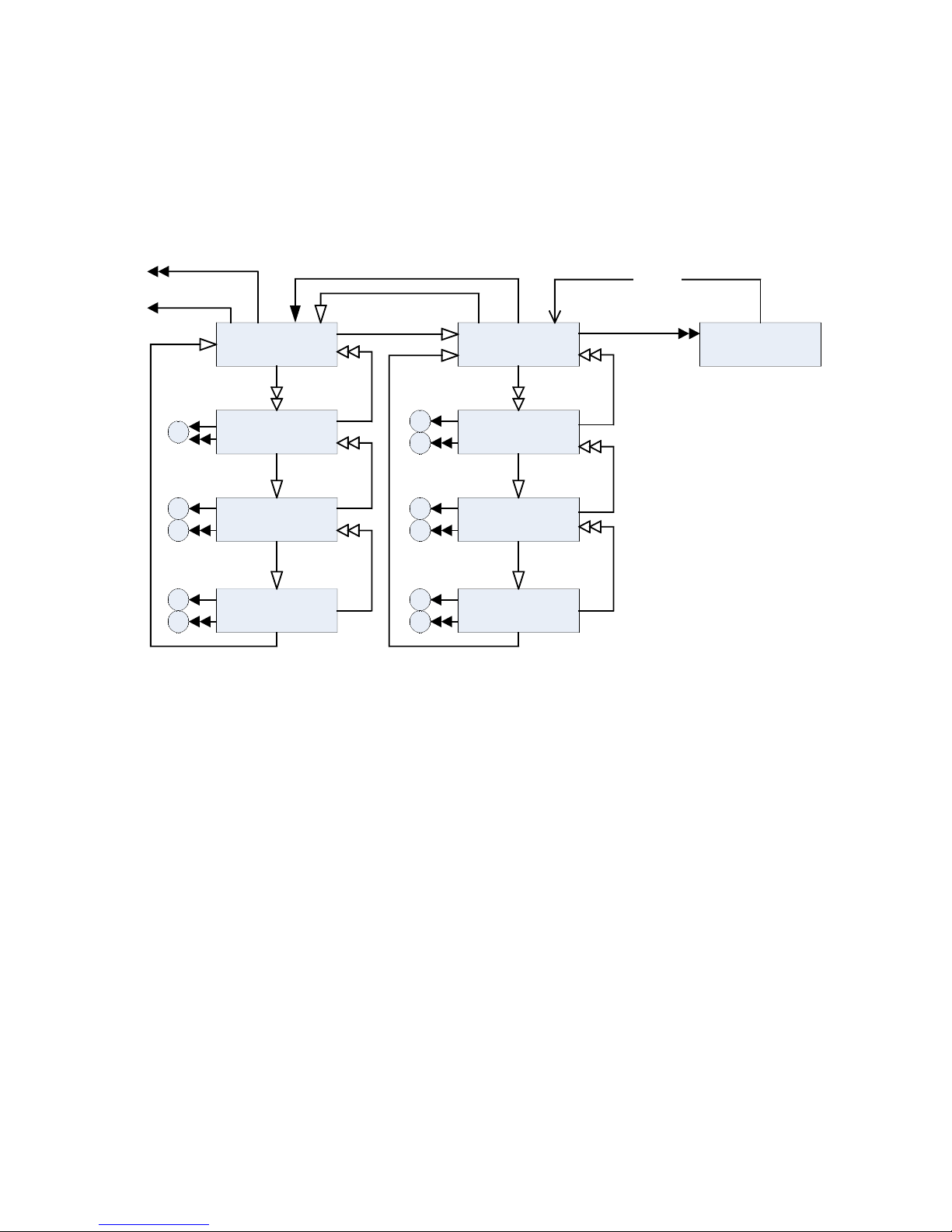
When the clock is powered it automatically enters the time state. A short pus h of SW1 pushbutton
will change the time state into the date state. Next short push of any button will return to the time
state again. A short push of SW2 pushbutton will change the time state to the tube's lifetime counter
state. Next short push of any button will retur n to the time state again. If the clock is left in the date
state or tube's lifetime counter state and none of the buttons is pressed within 30 seconds, timeout
occurs and the clock automatically returns to the time state.
Toggle:
DD/MM/YY
MM/DD/YY
DateTime
Set day
Set month
Set week
Set seconds
Set minutes
Set hours
+
-
+
-
+
-
+
-
+
-
0
Auto return
To 2 branch
Tube’s Lifetime
Counter State
Fig. 12. Menu diagram. 1 branch
3.3 Setting time
When present time is shown, push and hold the SW1 pushbutton. After 3 seconds, the seconds will
start blinking. A short push to SW2 will reset seconds to 00. A short push to SW1 will enter the
minutes setting and minutes display will start blinking. A short push to SW2 will increase the
minutes value by 1, a long push to SW2 will decrease the minutes by 1. Again, a short push to SW1
will enter the hour setting mode and hour display will start blinking. A short push to SW2 will
increase the hour value by 1, a long push to SW2 will decrease the hour by 1. A short push to SW1
will lead to escape the time setting mode and the clock will return to the actual time display.
During the settings, time is not rounded (e.g. when the seconds are reset, the minutes value will
remain the same). If 12-hour mode is selected, the clock will automaticall y convert time to the 24hour format during settings and convert back on exit.
If a GPS receiver is connected time synchronization will be performed automatically and entering to
the time setting menu will not be allowed. If a GPS receiver is connected and time does not
represent your local time, check the time-zone and DST settings.
Page 11

3.4 Setting date
Short push to SW1 to enter the date state. There are two date display modes: DD/MM/YY and
MM/DD/YY. A long push to SW2 will toggle between these modes. To set date, push and hold
SW1 while date is displayed. After 3 seconds day will start blinking. A short pus h to SW2 will
increase the day by 1, a long push to SW2 will decrease by 1. Next pushes to the SW1 will enter
month and year settings appropriately. Month and year settings should be performed in the same
way as day setting. Next push to SW1 will exit date setting mode.
If a GPS receiver is connected date synchronization will be performed automatically and entering to
the date setting menu will not be allowed. If a GPS receiver is connected and the date does not
represent your local time, check the time-zone and DST settings.
Page 12
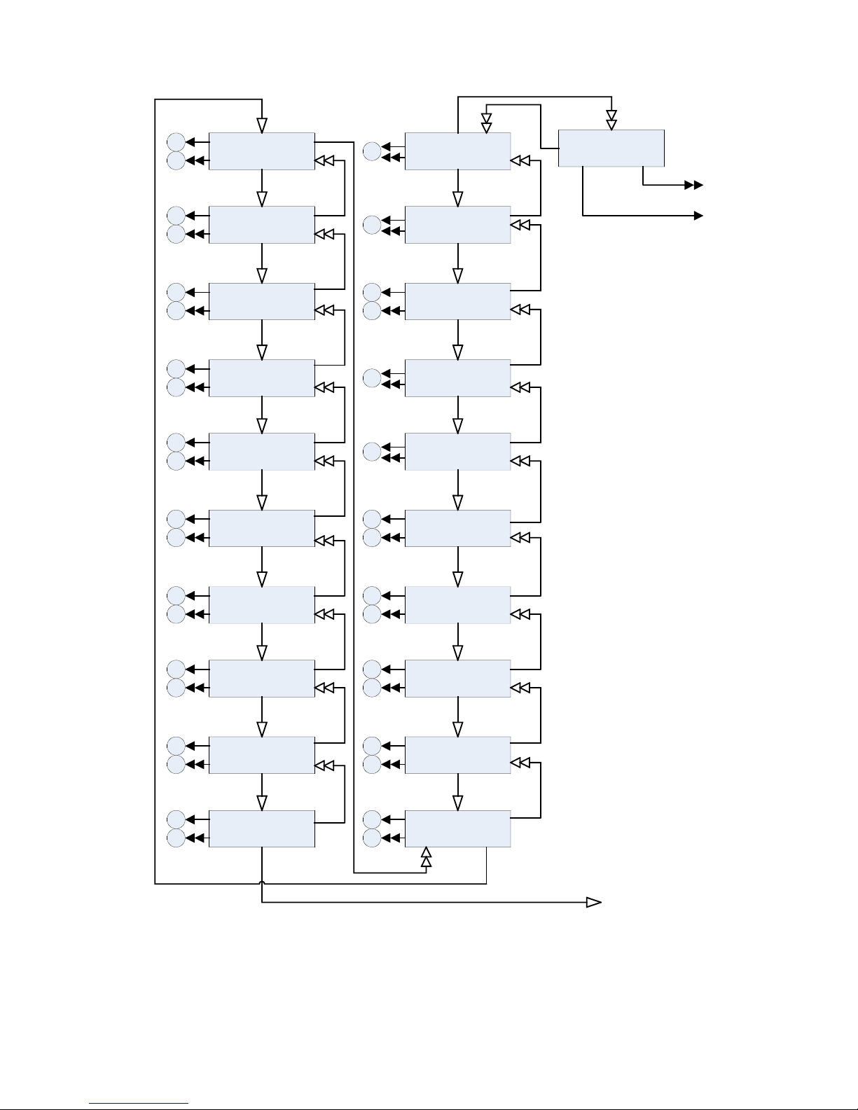
Fig. 13. Menu diagram. 2 branch
Tube’s Lifetime
Counter
Hour Format
12/24
Leading Zero
Column Separator
Mode
+
-
T
To 1 branch
Time State
Autorotate Date
Reset Tube’s
Lifetime Counter
Night Shut-Down
Minutes
+
-
T
Night Shut-Down
Hour
Morning Wake
Minutes
Morning Wake
Hour
+
-
+
-
DST Vernal
Hour
DST Vernal
Weekday
DST Vernal
Week
+
-
+
-
DST Vernal
Month
DST Autumnal
Hour
DST Autumnal
Weekday
+
-
+
-
DST Autumnal
Week
DST Autumnal
Month
Crossfading
Deep
+
-
+
-
Tube’s Refresh
Rate
+
-
Time Zo n e
+
-
1
2
3
4
5
6
7
8
9
10
11
12
13
14
15
16
17
18
19
20
T
0
+
-
+
-
+
-
+
-
To 1 branch
Time State
Page 13

3.5 Tube's lifetime counter
The tube's lifetime counter counts hours when the tubes are lit. During the night shut-down (if
enabled) hours are not taken into account. Counter counts until 65535 hours, then overflow occurs
and counter will start again from zero.
To enter the tube's lifetime counter press SW2 when time is shown. The tube's lifetime counter can
be reset via the settings menu. The data is stored in the battery back upped memory, so it will not be
lost during power off.
3.6 Settings menu
To enter the settings menu push and hold SW1 for 3 or more seconds when the tube's lifetime
counter state is present. When the settings mode is entered, on the most left tubes settings number is
shown, which corresponds with the actual parameter (later this number will be enclosed in
parenthesis). To set the next parameter push SW1 shortly. To return to the previous parameter push
SW1 for 3 or more seconds. When the last parameter (20) is entered next short push to the SW1 will
return the clock into the time state. See fig.3.
3.6.1 Hour format (1)
There are t wo modes availabl e 12- hour and 24-hour. Thes e modes can be toggled pushing SW2.
The actual mode is shown on the most right tubes. For AM/PM mode see chapter 3.4.3
Default mode: 24-hour.
3.6.2 Leading zero (2)
The clock can display time with leading zero or it can be blanked (e.g. 01:23:45 or 1:23:45). These
modes can be toggled pushing SW2. The actual mode is shown on the most right tubes.
Default mode: leading zero is shown.
3.6.3 Column separator mode (3)
Column separator bulbs can be set in one of the four modes. Select desired mode using SW2.
● Mode 0. Column separator bulbs are disabled
● Mode 1. Column separator bulbs are lit all the time
● Mode 2. Column separator bulbs blink by 1Hz
● Mode 3. Column separator bulbs shows AM/PM mode (lit when PM)
The actual mode is shown on the most right tubes.
Default mode: 2.
3.6.4 Auto rotate date (4)
The clock can automatically show date between 50 and 55 seconds every minute. Automatic change
occurs in time state only. It is recommended to enable this option, since visual effects performed
during display change prevents the unused cathodes of the nixie tubes from poisoning. Select
desired the mode using SW2. The actual mode is shown on the most right tubes.
● Mode 00. Auto rotate is diabled
Page 14

● Mode 01. Auto rotate is enabled
Default mode: enabled (in firmware v1.0 and v1.1 default mode - disabled).
3.6.5 Reset tube's lifetime counter (5)
To reset the tube's lifetime counter press SW2. When the counter is reset, 00 will appear on the
most right tubes.
3.6.6 Night shut-down minute (6)
The clock can automatically disable the tubes during preset time (e.g. night time). This function
involves 4 settings (night shut-down minute, night shut-down hour, morning wake-up minute,
morning wake-up hour). During the time between shut-down and wake up the tubes will be
disabled. If any button is pressed while the tubes are disabled, the clock will wake up for 10 seconds
and then will shut down again. After 3 wake-ups tubes will remain enabled until the next shut down
time. This functi on may be disabled by setting the same time (minutes and hours) for shut-down
and wake-up. In this case the tubes will be lit all the time.
Set the night shut-down minutes using SW2.
Default minute: 00.
3.6.7 Night shut-down hour (7)
Set the night shut-down hour using SW2.
Default hour: 00. (12-AM)
Note: regardless of the setting of the clock hour mode (12 or 24 hour), hours during settings always
will be displayed in 24-hour format.
3.6.8 Morning wake-up minute (8)
Set the morning wake-up minutes using SW2.
Default minute: 00.
3.6.9 Morning wake-up hour (9)
Set the morning wake-up hour using SW2.
Default hour: 06. (06-AM)
3.6.10 Time zone (10)
If a GPS receiver is connected, the clock must know your time zone to synchronize the time
properly (in fact GPS service is a global service and provided time is GMT regardless of position).
Select you time zone using SW2. The two middle tubes show offset hour, the two right ones show
offset minutes. Blinking tubes means negative offset according to GMT, constantly lit tubes means
positive offset.
Default time zone: 00:00.
Page 15

3.6.11 DST vernal hour (11)
The clock ca n aut omatically adjust time according to your local daylight saving time (DST). Since
the beginning of DST and reverting to the standard time varies across the world, you shoul d set it
accordingly to your local country rules. On the vernal change the clock is turned forward an hour
and on the autumnal change reverted back. Each autumnal and vernal setting involves 4 settings
(total 8). These settings are: hour, weekday, week of the month and month. Actual weekday is
calculated automatically according to the actual date. If a GPS receiver is connected, DST
correction applies as well. If you don not need DST correction, set the sa me values to all vernal and
autumnal settings.
Set DST vernal hour using SW2. Hour is shown on the most right tubes.
Default hour: 01. (01-AM)
Note: regardless of the setting of clock the hour mode (12 or 24 hour), hours during settings always
will be displayed in 24-hour format.
3.6.12 DST vernal weekday (12)
Set the DST vernal weekday using SW2. The weekday is shown on the most right tube. 1 means
monday; 7- sunday.
Default weekday – 7 (sunday).
3.6.13 DST vernal week (13)
Set the DST ver nal week of the month using SW2. The week is shown on the most right tube. 1
means first week of month; 5- last week of month (regardless how many weeks this month have).
Default week of month – 5 (last week).
3.6.14 DST vernal month (14)
Set the DST vernal month using SW2. The month is shown on the most right tubes.
Default month – 3 (march).
3.6.15 DST autumnal hour (15)
Set the DST autumnal hour using SW2. The hour is shown on the most right tubes.
Default hour: 01. (01-AM)
3.6.16 DST autumnal weekday (16)
Set the DST autumnal weekday using SW2. The weekday is shown on the most right tube. 1 means
monday; 7- sunday.
Default weekday – 7 (sunday).
3.6.17 DST autumnal week (17)
Set the DST autumnal week of the month using SW2. The week is shown on the most right tube. 1
means first week of month; 5- last week of month (regardless how many weeks this month have).
Default week of month – 5 (last week).
Page 16
3.6.18 DST autumnal month (18)
Set the DST autumnal month using SW2. The month is shown on the most right tubes.
Default month – 10 (october).
3.6.19 Crossfading deep (19)
The clock can fade one digit while simultaneously fading into a second digit creating smooth
appearance of digit change. During crossfading di gits are blinked up to several hundre ds times with
variable duration. Smoothness of crossfading may be set using SW2. Available range is 1-25.
Default value: 20.
3.6.20 Tube's refresh rate (20)
The clock uses multiplex mode of tubes driving, so the tubes flickers in pairs all the time. The
flicking rate is very high and eyes can't distinguish it, therefore it creates an illusion of being
constantly lit. Although in some cases flicking rate may correspond the tube's internal construc tions
resonance frequency and may lead to hearable buzzing. One of the three refresh rates can be chosen
using SW2. 1 corresponds with the highest refresh rate, 3 – with the lowest one. If the lowest one
(3) is chosen, deep cr osfading (more than 15) may not look good because the tubes do not flick fast
enough to show enough number of shapes with variable duration.
Default value: 2.
Note: refresh rate selection does not influent brightness much. To select brightness, use R26
potentiometer onboard. Do not exceed voltage limit (170V).
3.7 Reset settings values to default
First time when the clock is connected to the power supply, all settings are set to default
automatically. If you want to reset all values to default manually, do the following sequence:
disconnect the power supply, hold both pushbuttons (SW1 and SW2) pres sed and connect the
power supply, release the pushbuttons.
4 GPS synchronization
To keep time and date accurate all the time a GPS receiver can be connected. It is optional since
clock has internal RTC (Real Time Clock) as a time base and is fully functional without a GPS
receiver. If a GPS receiver is connected, the clock's firmware automatically detects it and
periodically updates internal RTC time and date according to the time provided by the GPS satellite.
Page 17
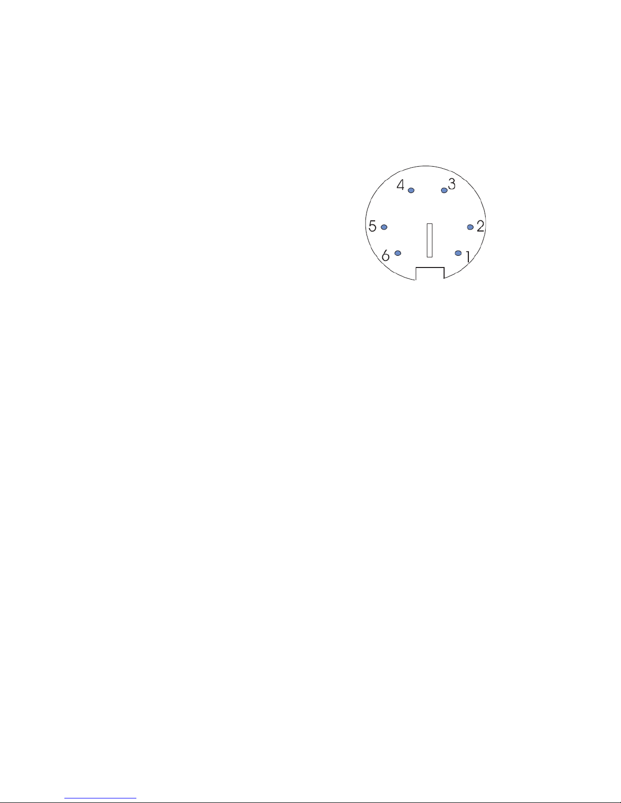
Fig. 14. GPS receiver
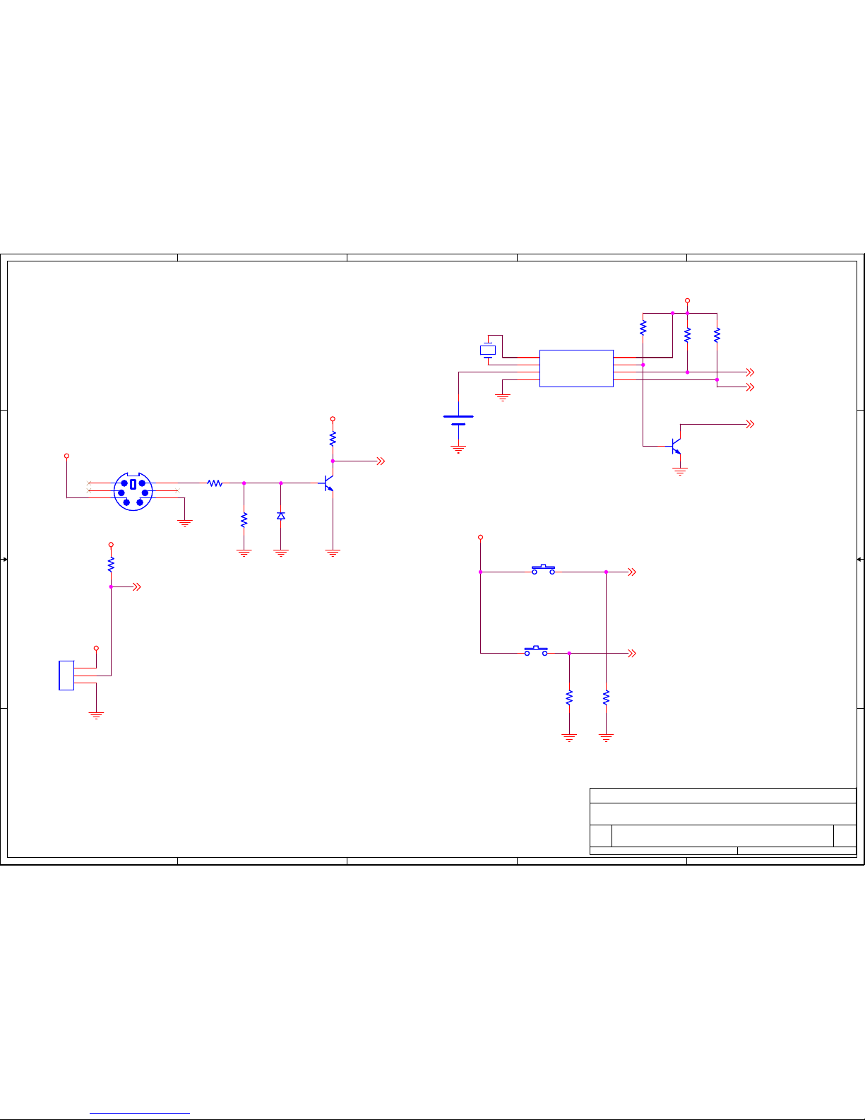
A GPS receiver should be NMEA-0183 standard compatible and should be able to provide GPRMC
sentences via RS232 interface at 4800 baud. A required PS/2 type connector usually is used with
the receivers for PDAs. Compatible receiver s are: “NAVILOCK NL-208P”, “HAICOM HI-204III”
and many others.
GPS female connector pinout:
1. Not connected
2. Not Connected
3. +5V Power supply
4. Ground
5. Not connected
6. RS232 TX
Page 18

4.1.1 Technical data
4.2 Software
● Time display
■ 12-hour mode
■ 24-hour mode
■ AM/PM indication
■ Programmable leading zero suppression
■ Programmable DST correction
● Date display
■ DD/MM/YY mode
■ MM/DD/YY mode
■ Leap year correction
● Programmable column separators
● Programmable tubes shut-down during night time
● Crossfading with selectable deep
● Three visual effects
● Selectable refresh rate of tubes
● Tube's lifetime counter (16-bit, up to 65535 hours)
● GPS time and date synchronization (GPS receiver is optional)
● Selectable time-zone
● Cathode poisoning prevention
● Tube testing routine
4.3 Hardware
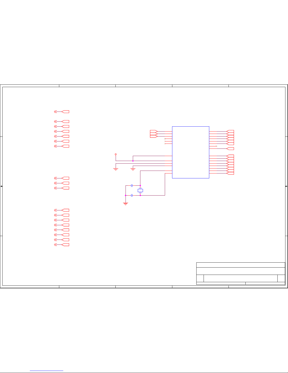
● Microchip PIC16F876A main controller
● Real Time Clock with battery back-up (CR2032 Lithium battery)
● Tube's drive mode: 3x2 multiplex
● High voltage power supply with PWM control and software shut-down
● RS232 levels serial input
● 2 pushbuttons
● Power supply: 9-12V @ 500-1000mA DC; 5.5/2.5mm jack with positive inner
(recommended 12V 1A DC PSU. It does not matter stabilized or not)
● Incorrect polarity protection
● High precision (10ppm) timebase XTAL
Page 19
5
5
4
4
3
3
2
2
1
1
D D
C C
B B
A A
A3_T2
A3_T1
A2_T2
A2_T1
A1_T2
A1_T1
VCC_HI_T2
VCC_HI_T1
COLON_T
A3_T1
COLON_T
VCC_HI_T1
A2_T1
A1_T1
A3_T2
COLON_T
A2_T2
VCC_HI_T2
A1_T2
VCC5
VCC5
0 0
0 0
000
LO_A1
LO_A0
LO_A3
HI_A3
LO_A2
HI_A2
Vcc_HI
HI_A1
HI_A0
A3
A2
A1
COLON
Vcc_HI
Title
Size Document Number Rev
Date: Sheet
of
NCV2, Copyright 2006, TubeHobby
2.1
High Voltage Drivers
A4
14Saturday, April 22, 2006
Title
Size Document Number Rev
Date: Sheet
of
NCV2, Copyright 2006, TubeHobby
2.1
High Voltage Drivers
A4
14Saturday, April 22, 2006
Title
Size Document Number Rev
Date: Sheet
of
NCV2, Copyright 2006, TubeHobby
2.1
High Voltage Drivers
A4
14Saturday, April 22, 2006
R19
10K
R19
10K
R16
100K
R16
100K
R31
10K
R31
10K
R18
10K
R18
10K
R10
470K
R10
470K
Q6
MPSA92
Q6
MPSA92
R8
100KR8100K
Q2
MPSA42Q2MPSA42
R15
10K
R15
10K
Y0
16
Y1
15
Y2
8
Y3
9
Y4
13
Y5
14
Y6
11
Y7
10
Y8
1
Y9
2
A0
3
A1
6
A2
7
A3
4
Vdd
5
Gnd
12
U2
K155ID1U2K155ID1
Y0
16
Y1
15
Y2
8
Y3
9
Y4
13
Y5
14
Y6
11
Y7
10
Y8
1
Y9
2
A0
3
A1
6
A2
7
A3
4
Vdd
5
Gnd
12
U3
K155ID1U3K155ID1
R24
10K
R24
10K
Q9
MPSA42Q9MPSA42
R11
470K
R11
470K
R22
100K
R22
100K
C4
10NC410N
R20
10K
R20
10K
R12
100K
R12
100K
R32
10K
R32
10K
Q8
MPSA92
Q8
MPSA92
Q5
MPSA92
Q5
MPSA92
R21
10K
R21
10K
R23
470K
R23
470K
C8
10NC810N
Q3
MPSA42Q3MPSA42
R17
10K
R17
10K
R9
100KR9100K
1
2
3
4
5
6
7
8
9
10
11
12
13
14
15
16
17
18
19
20
21
22
23
24
25
26
27
28
29
30
J4
CON30J4CON30
Page 20
5
5
4
4
3
3
2
2
1
1
D D
C C
B B
A A
RC3
RC4
RB7
RB6
RB5
RB4
RB3
RB2
RB1
RB0
RC0
RC1
RC2
RC5
RB7
RB6
RB5
RB4
RB3
RB2
RB1
RB0
RA2
RA1
RA2
RA1
RA0
RC2
RC1
RA0
RC0
RC5
RC3
RC4
RC7
RC7
0
0 0
VCC5
HI_A3
HI_A2
HI_A1
HI_A0
LO_A3
LO_A2
LO_A1
A3
A2
LO_A0
PS_DOWN
SDA
SW1
A1
SCL
SW2
DCF77
RX
Title
Size Document Number Rev
Date: Sheet
of
NCV2, Copyright 2006, TubeHobby 2.1
Microcontroller Unit
A4
24Saturday, April 22, 2006
Title
Size Document Number Rev
Date: Sheet
of
NCV2, Copyright 2006, TubeHobby 2.1
Microcontroller Unit
A4
24Saturday, April 22, 2006
Title
Size Document Number Rev
Date: Sheet
of
NCV2, Copyright 2006, TubeHobby 2.1
Microcontroller Unit
A4
24Saturday, April 22, 2006
Y1
20MHZY120MHZ
C3
22PC322P
RA0/AN0
2
RA1/AN1
3
RA2/AN2/Vref-
4
RA3/AN3/Vref+
5
RA4/T0CKI
6
RA5/AN4/_SS
7
RC0/T1OSO/T1CKI
11
RC1/T1OSI/CCP2
12
RC2/CCP1
13
RC3/SCK/SCL
14
RC4/SDI/SDA
15
RC5/SDO
16
RC6/TX/CK
17
RC7/RX/DT
18
RB0/INT
21
RB1
22
RB2
23
RB3/PGM
24
RB4
25
RB5
26
RB6/PGC
27
RB7/PGD
28
Vss1
8
Vss2
19
Vdd
20
OSC1/CLKIN
9
OSC2/CKOUT
10
_MCLR/Vpp/THV
1
U4
PIC16F876
U4
PIC16F876
C5
22PC522P
Page 21
5
5
4
4
3
3
2
2
1
1
D D
C C
B B
A A
000 0 0 0 0 0
00
00
0
VCC5
0
0
0
Vcc_HI
PS_DOWN
Title
Size Document Number Rev
Date: Sheet
of
NCV2, Copyright 2006, TubeHobby 2.1
Power supply
A4
34Sunday, July 30, 2006
Title
Size Document Number Rev
Date: Sheet
of
NCV2, Copyright 2006, TubeHobby 2.1
Power supply
A4
34Sunday, July 30, 2006
Title
Size Document Number Rev
Date: Sheet
of
NCV2, Copyright 2006, TubeHobby 2.1
Power supply
A4
34Sunday, July 30, 2006
Voltage
R27
100K
R27
100K
C6
1U 250VC61U 250V
C1
10UC110U
R29
5.6K
R29
5.6K
L1
270UHL1270UH
D3
1N4148D31N4148
R28
10K
R28
10K
Vin
1
Gnd
2
Vout
3
U1
LM7805U1LM7805
R30
15K
R30
15K
F1
FUSE 0.8A
F1
FUSE 0.8A
M1
IRF640M1IRF640
C9
10NC910N
D1
1N4007D11N4007
C7
330NC7330N
3
2
1
J2
CONN JACK PWR
J2
CONN JACK PWR
R141KR14
1K
D2
UF4007D2UF4007
R6
910KR6910K
1+
1
1-
2
COMP
3
DTC
4
Ct
5
Rt
6
Gnd
7
C1
8
E1
9
E2
10
C2
11
Vcc
12
OC
13
Vref
14
2-
15
2+
16
TL494U5TL494
U5
C2
470UC2470U
R26
22K
R26
22K
Q4
2SA1266Q42SA1266
R7
220R7220
Page 22
5
5
4
4
3
3
2
2
1
1
D D
C C
B B
A A
VCC5
0
0
0
VCC5
VCC5
0
VCC5
0
VCC5
0
VCC5
0
0
0
0
SW2
SW1
SDA
DCF77
SCL
COLON
RX
Title
Size Document Number Rev
Date: Sheet
of
NCV2, Copyright 2006, TubeHobby 2.1
Peripheral
A4
44Sunday, July 30, 2006
Title
Size Document Number Rev
Date: Sheet
of
NCV2, Copyright 2006, TubeHobby 2.1
Peripheral
A4
44Sunday, July 30, 2006
Title
Size Document Number Rev
Date: Sheet
of
NCV2, Copyright 2006, TubeHobby 2.1
Peripheral
A4
44Sunday, July 30, 2006
1
2
3
J3
DCF77J3DCF77
R33
10k
R33
10k
R25
10K
R25
10K
6
4
2
5
3
1
J1
GPSJ1GPS
Q7
MPSA42Q7MPSA42
SW1SW1
R13
10k
R13
10k
Q1
MPSA42Q1MPSA42
R2
100kR2100k
R3
10kR310k
Y2
32.768KHz
Y2
32.768KHz
D4
1N4148D41N4148
SW2SW2
+
V1
3V Lithium Battery
+
V1
3V Lithium Battery
R5
10kR510k
R4
10kR410k
R34
10k
R34
10k
R1
10kR110k
X1
1
X2
2
Vbat
3
Gnd
4
Vdd
8
SQW/OUT
7
SCL
6
SDA
5
U6
DS1307U6DS1307
Page 23
5
5
4
4
3
3
2
2
1
1
D D
C C
B B
A A
H1
H2
H3
H4
H5
H6
H7
H8
H9
H0
H8
H2
H0
H6
H4
H3
H9
H7
H5
H1
H8
H2
H0
H6
H4
H3
H9
H7
H5
H1
H8
H2
H0
H6
H4
H3
H9
H7
H5
H1
L8
L2
L0
L6
L4
L3
L9
L7
L5
L1
L6
L2
L5
L4
L0
L8
L7
L9
L3
L1
L6
L2
L5
L4
L0
L8
L7
L9
L3
L1
L6
L2
L5
L4
L0
L8
L7
L9
L3
L1
A2_T2
A1_T2
VCC_HI_T1
A2_T1
A1_T1
COLON_T
COLON_T
A3_T1
A3_T2
VCC_HI_T2
A1_T1
A1_T2
A2_T1
A2_T2
A3_T1
A3_T2
VCC_HI_T1 VCC_HI_T2COLON_T COLON_T
Title
Size Document Number Rev
Date: Sheet
of
NCV2, Copyright 2006, TubeHobby 1.0
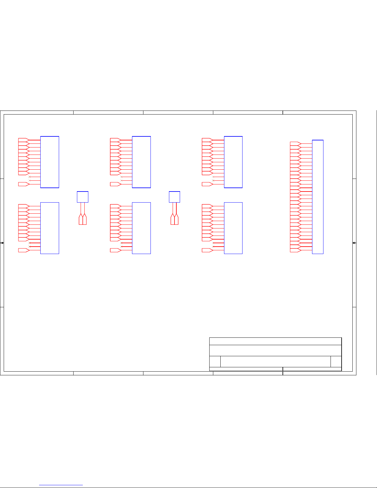
IN-14 Tube's Board
A
11Monday, December 13, 2010
Title
Size Document Number Rev
Date: Sheet of
NCV2, Copyright 2006, TubeHobby 1.0
IN-14 Tube's Board
A
11Monday, December 13, 2010
Title
Size Document Number Rev
Date: Sheet of
NCV2, Copyright 2006, TubeHobby 1.0
IN-14 Tube's Board
A
11Monday, December 13, 2010
T1 T2 TS1 T3 T4 TS2 T5 T6
Hours
Minutes
Seconds
1
3
2
4
3
5
4
6
5
7
6
8
7
9
8
10
9
11
0
12
D1
2
D2
13
A
1
T3
IN-14T3IN-14
1
3
2
4
3
5
4
6
5
7
6
8
7
9
8
10
9
11
0
12
D1
2
D2
13
A
1
T2
IN-14T2IN-14
A1C
2
TS2
IN-3
TS2
IN-3
1
3
2
4
3
5
4
6
5
7
6
8
7
9
8
10
9
11
0
12
D1
2
D2
13
A
1
T1
IN-14T1IN-14
1
3
2
4
3
5
4
6
5
7
6
8
7
9
8
10
9
11
0
12
D1
2
D2
13
A
1
T6
IN-14T6IN-14
1
3
2
4
3
5
4
6
5
7
6
8
7
9
8
10
9
11
0
12
D1
2
D2
13
A
1
T5
IN-14T5IN-14
A1C
2
TS1
IN-3
TS1
IN-3
1
3
2
4
3
5
4
6
5
7
6
8
7
9
8
10
9
11
0
12
D1
2
D2
13
A
1
T4
IN-14T4IN-14
1
2
3
4
5
6
7
8
9
10
11
12
13
14
15
16
17
18
19
20
21
22
23
24
25
26
27
28
29
30
J3J1J3
J1
Page 24
Page 25
Page 26
Page 27
Page 28
Gas discharge indicator type IN-14 (ИН-14)
Datasheet translated by TubeHobby
www.tubehobby.com
Description
Gas discharge indicator is intended for visual indication of electrical signals in digital
form in broad kind of equipment.
Connection diagram
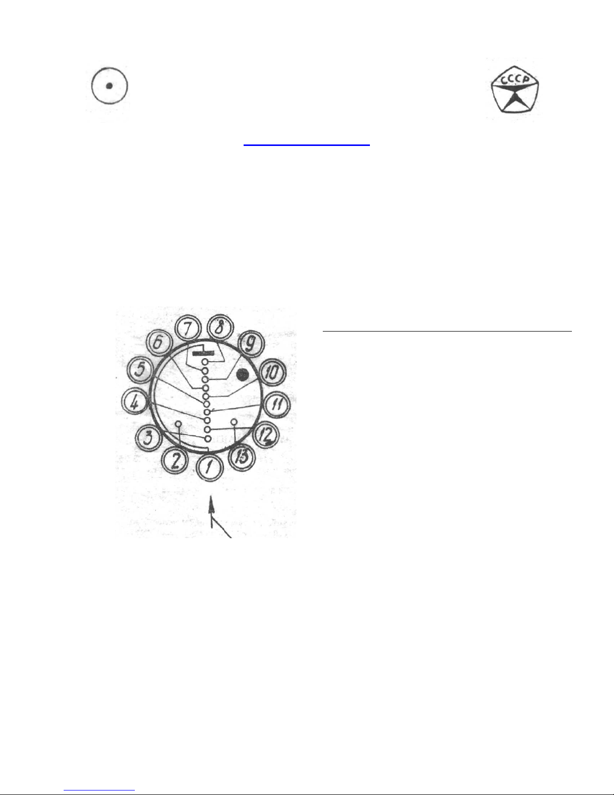
Pins are counted clockwise from pin #1 which is shown by arrow on glass body
underneath the plastic spacer. Pins are counted looking to the tube from the pin’s side
(bottom).
Arrow on glass
Pin
number
1 Anode
2 Cathode comma
3 Cathode “1”
4 Cathode “2”
5 Cathode “3”
6 Cathode “4”
7 Cathode “5”
8 Cathode “6”
9 Cathode “7”
10 Cathode “8”
11 Cathode “9”
12 Cathode “0”
13 Cathode comma
Description
Page 29

Basic electrical and lighting parameters
Firing voltage (no more than) 170V
Current for digits (no more than) 2.5mA
Current for commas (no more than) 0.3mA
Brightness (no less than) 100 cd/m²
Viewing angle (no less than) +/- 30º
Allowable limits
Power supply voltage 200V
Current for digits 2.0 - 3.5mA
Current for commas 0.3 – 0.7mA
Average current (supplying from mains 50Hz via single-period rectifier)
Current for digits (no more than) 2.0mA
Current for commas (no more than) 0.2mA
Multiplex mode
Power supply voltage 190V
Average current for digits 0.7 - 1.5mA
Average current for commas 0.15 – 0.6mA
Pulse current for digits 7 – 13mA
Pulse current for commas 1.5 – 5mA
Pulse width (no less than) 70µS
Period 1 – 1.8 kHz
Tube does not contain precious metals.
Notes
Pin soldering and bending should be performed at least 5mm away from the glass body.
Avoid multiple soldering – desoldering.
After long period of non-use it is recommended to train cathodes applying working
current for 1 minute for each cathode.
 Loading...