

TubeDepot Tweed 5F1 Assembly Manual

Learn Build Play
Assembly Manual
Tweed 5F1
Instructions for Assembling with the:
- Printed Circuit Board (PCB)
with additional modification suggestions and recommended amp settings
version 17.0
May 24, 2017

This manual was developed and published by:
ii TubeDepot.com
TubeDepot.com
Memphis, TN
Written by:
Robert Hull
Edited by:
Mary Klaebel JP Phelps
Design and artwork by:
Robert
Hull
Mary Klaebel
Christian Magee
Acknow
ledgements:
Special thanks to:
Joe Austin Mitchell Bird Rees Shad
Caleb K
im Matt Kirby
Henry Lum Joe Moffett
Brian Overstreet Ben Siler
Doug Sims John Puffer
Rex Cuizon
Copyright © 2009
TubeDepot.com
1958 Vanderhorn Drive
Memphis, TN 38134
(877)289-7994
info@tubedepot.com
REGARDING THESE BOOK MATERIALS
Reproduction, publication, or duplication of this booklet, or any part thereof, in any manner, mechanically,
electronically, or photographically is prohibited without the express written permission of the publisher.
The Author
For permi
, Publisher or Seller assume no liability with respect to the use of the information contained herein.
ssion and other rights under this copyright, contact TubeDepot.com.

page
Table of Contents
TubeDepot.com iii
Preface and Tweed 5 F 1 over view ....................................................................................... iv
Chapter 1
Safety ….........................................................................................................................1
Chapter 2
Tools and Supplies ….....................................................................................................2
Chapter 3
Parts Inventory ...........................…................................................................................3
Chapter 4
Cabinet Preparation …....................................................................................................4
Chapter 5
Circuit Assembly (PCB)…...............................................................................................5
Chapter 6
Chassis Preparation and Assembly …..........................................................................10
Chapter 7
Final Assembly …...........................................................................................................9
Chapter 8
Testing …......................................................................................................................20
Chapter 9
Schematics and Parts Lay out …...................................................................................23
Chapter 10
Cool Modifications …....................................................................................................28
Appendix
A. How to Read Resistor and Capacitor Codes ….......................................................29
B. Soldering Hints ….....................................................................................................32
C. Amplifier Care, Feeding, and Application Hints …...................................................34
D. Drilling Templates …................................................................................................36

Short History of the Tweed Fender Champ
Preface
TM
TM
TM
TM
iv TubeDepot.com
With just 4 watts, the first incarnation of the Fender Champ was introduced in 1948 and
was called the “Champion 800”. It had one 6SJ7 preamp tube, a single 6V6 power tube, and
a 5Y3 rectifier tube. Along with an 8” speaker, it was covered in two toned brown and tan vinyl
and was beautiful to behold. In 1953 the name changed to “Champion 600 ” with a 6”
speaker replacing the original 8”. The two toned vinyl remains, however some of the later
Champion 600's are covered in the new transition tweed covering. By 1953, all Champion
amps were covered in tweed and all still sounded great! These early Champions were the
perfect complement to the new Telecaster family of guitars. But all is not finished yet …
The biggest improvements were brewing. In 1955, the “Champ” is born with the introduction
of the new 12AX7A as the preamplifier tube (replacing the 6SJ7). This brings the output to 5
watts into a 6” speaker. But there is one more big improvement coming. In 1958, along with a
slight component change, the 8” speaker is reintroduced. With this final change, the “mother
of tone” is born. It is as if the planets aligned and whispered to Leo Fender what the near
perfect amp should sound like. He was listening because here it is.
It is this last, near perfect incarnation that we provide for you here.
The tweed champ is one of my favorite amps. Inside its diminutive size rests the heart of an
entire world of music. From blues, to rock-a-billy; from rock-n-roll to soul; from country to jazz,
this amp is capable of holding its own across a wide swath of musical history and genres.
From humble consideration as a “beginner amp”, this amp has become a standard bearer for
what is cool about music.
Therefore imagine my excitement in designing a kit where you can build an incredible amp
on which to put your musical mark on the world. Wow … this is going to be fun!
Thank you for purchasing this great kit. You should be able to easily put this kit together in
an evening or two … whether you have any prior amp building experience or not. I designed
this kit for you to enjoy both building and playing this amp. And once finished, this kit will allow
you to make the best music you can … to make your world mark.
Now, let's have some building and playing fun.
Robert Hull
Director of Technical Services
TubeDepot.com
“Champ” and “Fender” are the property of Fender Musical Instruments Corporation (FMIC). TubeDepot is not
affiliated or associated with FMIC or its subsidiaries and FMIC does not sponsor or endorse any of TubeDepot’s
products.

1
Safety
- DISCLAIMER -
subsidiaries accept no liability for any damage(s), injury(s) or death incurred from
or while building or using this kit.
construction methods are fo
particular procedure in this assembly manual differs from the assembly video, our
recommendation is to follow this manual to insure the best construction possible.
- Used when identifying an action that may cause phys ic al inj ur y or death.
WARNING
- Used when identifying an action that may cause damage to components
and/or equipment.
CAUTION
NOTE
- Used when identifying general points of interest.
TubeDepot.com 1
!!! Read these safety precautions before continuing !!!
ALL tube amplifiers contai n LETHAL VOLTAGES, often several hundred volts which WILL
leave burnt entrance and ex it wounds in skin. These voltages have the potential to cause
permanent physical damage and death. These voltages are present when the amp is
turned on and also for some time after the amp has been turned off. You can still get
shocked with a tube amp turned off and disconnected from AC power.
The above statement is a bit scary, but we want to stress that every piece of electronic
equipment must be treated with respect. When AC power is applied, there is always a chance
for injury or death. With tube amps, even when the AC power is not applied there is still
danger. Being shocked with high voltage is very painful and we do not want anyone finding
out the hard way.
When building this kit, we want your experiences to be both enjoyable and safe. There are
more kits to assemble and we want you to enjoy building and playing them all.
TubeDepot.com, its employees, officers, shareholders, investors and
TubeDepot.com reserves the right to make changes to this manual as new
und to be more efficient and/or safer. When a
Throughout this manual at key points in the construction, we have annotated important
steps with the below alerts. For your safety and to improve construction quality, It is important
that you become familiar with each of these alerts and adhere to their recommendations when
they appear.
Explanation of Alerts

2
Tools and Supplies
2 TubeDepot.com
As with any construction project, there are certain tools and supplies that are recommended
to complete the project. These are tools and supplies not provided with the kit and are instead
provided by the builder.
TubeDepot.com
The following is our recommended list: part number
Phillips screwdriver, #1 and #2 TL-VTSCRSET8
Slip joint pliers
Needle nose pliers TL-VT33
Wire cutters, diagonal TL-VT33
Wire strippers, for 18 and 20 awg wire TL-VT5021
Electric Drill
Drill bit, 3/16” - Chassis mounting in the cabinet
Drill bit, 5/32” - PCB and turret board chassis mounting
Drill bit, 1/8” - Fiberboard mounting
Masking tape, 2”
Ruler or scale, 12” w/ 1/16” markings
Permanent marker, fin e tip
Soldering iron, 25W – 40W (35W recommended) TL-WP35
Solder, electronics safe (60/40 w/ rosin core recommended) TS-24-6040-0027
Flux, electronic – liquid or paste (must be safe for electronic work) TS-83-1000-0186
De-soldering pump extract or TS-384-1000
Solder wick TS-1817-10F
Sponge
The following are really nice to have:
Soldering station w/ temperature control TL-WTCPT
Multimeter w/ DC range of at least 500 V TL-DVM850BL
Variable AC supply (Variac® style)
Current Limiting AC source (build directions in this manual)
Needle nose pliers – small size, for electronics work TL-NN7776
Wire cutters, diagonal – small size, for electronics work TL-170M
Center punch
Nutdrivers - 5/16”, 11/32”, 7/16”, 1/2”
Square, 9”
Scratch Awl
heat shrink, 1/8” x 6” TS-HS-ASST-7
De-burring tool
Fingernail polish (for holding nuts and screws in place)

TubeDepot.com 3
Parts Inventory
3
It is important to review all the parts that came with your kit. The list below is what you
should have received to complete your kit. If you find anything missing, contact us:
Qty Description Application
TubeDepot.com
1958 Vanderhorn Dr.
1 speaker, 8" Jensen MOD, 8 Ω (4 Ω available) speaker
1 chassis, steel chrome plated 5E1/5F1 chassis
1 cabinet, tweed 5E1/5F1 cabinet
1 PCB board, 5E1/5F1 _ printed circuit board
transformers
1 transformer, ClassicTone 40-18027
1 transformer, output tweed 5F1 4 & 8 ohm tap output transformer
tubes
1 5Y3 rectifier tube
1 6V6GT beam power tetrode power tube
1 12AX7 dual triode _ preamp tube
panel hardware
1 knob, vintage pointer
1 fuse holder, conical cap, vintage Fender style fuse holder
1 fuse, 3AG 2A slow-blow fuse
1 lamp holder lamp holder
1 jewel, re d lamp jewel
1 lamp, #47, 6.3 V lamp
2 jack, 12A, shorting, Switchcraft ¼" input jack
1 jack, 11A, open, Switchcraft ¼" speaker jack
3 washer, lock 3/8" jack lock washer
1 plug, Switchcraft ¼" speaker plug
power cord hardware
1 power cord, grounded three prong, 12'
1 strain relief, Heyco power cord strain relief
1 nylon cable clamp power cord clamp
1 screw, zinc plated #8 x 5/8", phillips flat head cord clamp mounting
tube sockets
1 socket, tube, miniature 9pin
2 socket, tube, octal rectifier / power tube
hardware
2 grommets, rubber 3/8" hole
2 bolt, 1 1/2" 10x32 truss screw chassis mounting
2 nuts, KEPS 10x32 chassis mounting
6 screw, zinc plated 6-32 x 1/4", phillips pan head tube socket mounting
9 nuts, KEPS 6x32 tube socket / PCB mounting
1 nuts, 6x32 tube socket w/ solder tab mounting
4 nuts, KEPS 8x32 power / output transformer mounting
2 nuts, 8x32 power transformer w/ solder tab mounting
4 screw, zinc plated 6-32 x 7/8" phillips pan head PCB mounting
4 standoff, nylon; L = .5"; id = .140"; od = .250" PCB mounting
2 screw, zinc plated 8-32 x 1/4", phillips pan head output transformer mounting
2 solder lug, locking, #8 screw grounding at power transformer
1 solder lug, locking, #6 screw grounding at preamp tube socket
1 wire nut power cord to power transformer wiring
electronic, resistors
2 100, 1/2w carbon film
2 68K, 1/2w carbon film input resistors
1 1M, 1/2w carbon film _ input biasing resistor
2 100K, 1/2w carbon film preamp tube plate resistors
rectifier tube
knob
preamp tube
grommets
filament pseudo center tap
power transformer
power cord
Memphis, TN 38134
(877) 289-7994
info@tubedepot.com

2 1.5K,
4 TubeDepot.com
1 22K, 1/2w carbon film feedback resistor
1 220K, 1/2w carbon film biasing resistor
1 470, 3w metal oxide cathode resistor
1 10K, 2w metal oxide B+ resistor
1 22K, 1w metal oxide B+ resistor
electronic, capacitors
2 .022ufd / 630v
2 22ufd / 50V cathode bypass caps
1 22ufd / 500V power supply filter cap
2 10ufd / 450V power supply filter caps
electronic, potentiometers
1 1M pot w/ on-off switch (Alpha )
1 100K trim pot, horizontal mount feedback adjustment
wire
3' wire, 20 awg, stranded, hi-temp PVC – yellow board, general wiring
2' wire, 20 awg, stranded, hi-temp PVC – red board, signal / B+ wiring
2' wire, 20 awg, stranded, hi-temp PVC – black board, ground wiring
3' wire, 18 awg, stranded, hi-temp PVC – green filament wire
2' wire, 18 awg, stranded, hi-temp PVC – black speaker wire, 2' wire, 18 awg, stranded, hi-temp PVC – white speaker wire, +
shielding
3” aluminum tape, 3" width, 10” length, self adhesive electrical and heat shielding
heat shrink
1 heat shrink, 1/4" - black, 6" piece wire dressing / capping
1/2w carbon film
coupling caps
preamp tube cathode resistors
volume / power switch
TubeDepot.com 5
4
Cabinet Preparation
photo 4.1a
4.1
photo 4.1b
Some printers may automatically reduce the size of the template when printed.
Therefore, prior to use, always physically measure the printed template to insure proper
scale is maintained.
CAUTION
The cabinet drilling template should be aligned to the cabinet's very edge. Verify correct
template placement before drilling. Do NOT bend the template to follow the curved edge.
Always measure several times before drilling.
CAUTION
photo 4.1c
photo 4.1c
This chapter deals with preparing the cabinet for installation of the completed chassis. But
first, we need to take inventory of the parts that came installed on the cabinet.
1. Handle w/ mounting hardware – There should be a single flat brown leather handle
with two metal securing ends all fastened to the cabinet with four screws.
2. Feet, chrome metal glide – There should be four metal feet attached with screws to
the underside of the cabinet.
3. Back panels, upper and lower with screws – There
should be two back panels. The top back panel should be
secured with four panel screws, the bottom panel should
be secured with two panel screws.
4. Baffle bolts with nuts – There should be four bronze
plated bolts attaching the baffle to the cabinet. The baffle
is secured with four KEPS nuts, one on each of these
bolts.
5. Speaker bolts with nuts – There should be four black
bolts exiting from the ba ffle board. There should be four
KEPS nuts (one on each of these black bolts) used for
mounting the speaker.
Drilling for the Two Chassis Mounting Bolts
Step 1 – Remove the amp handle from the top of cabinet
Step 2 – Remove the top back panel (place a small mark on the
inside of the panel to indicate which edge is up)
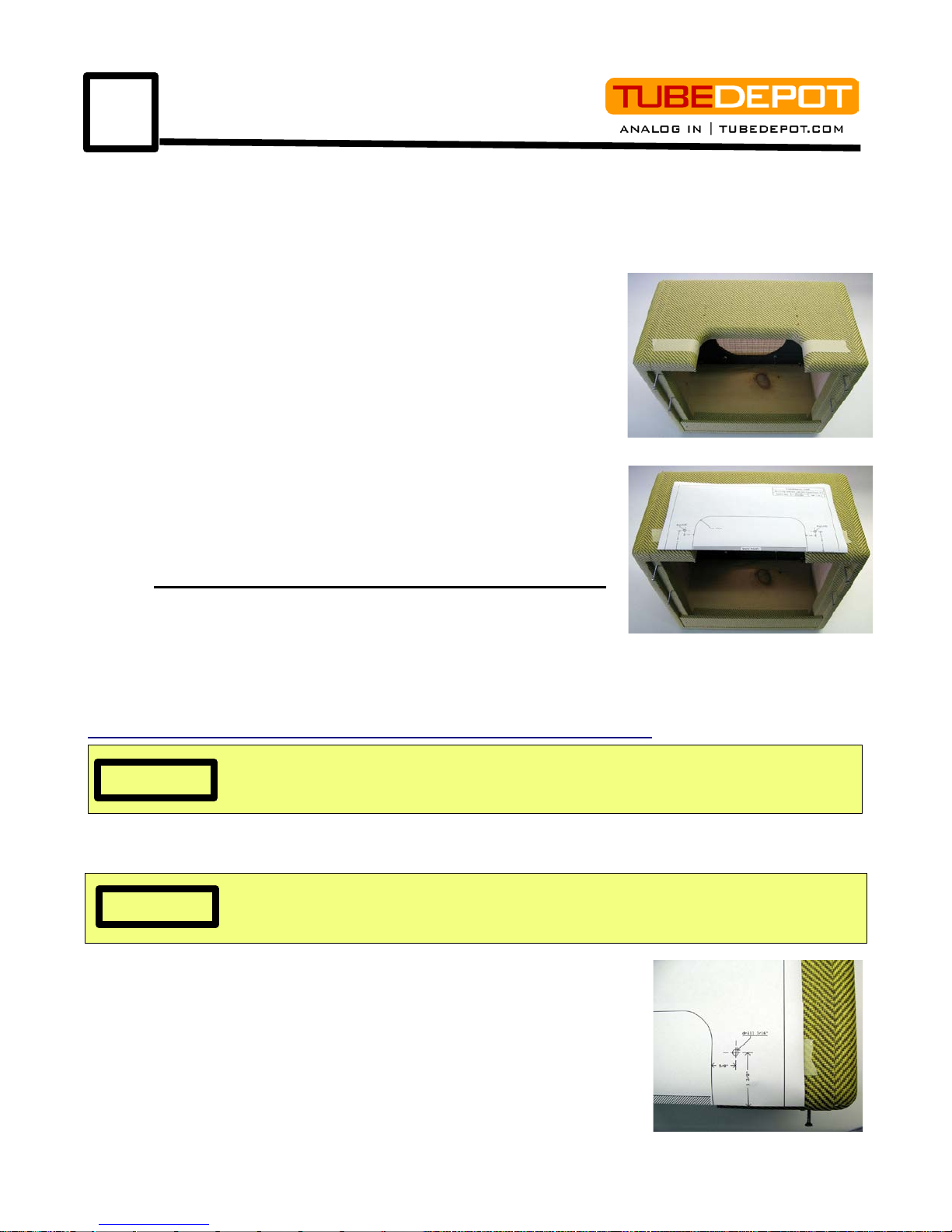
Step 3 – Apply masking tape on each side of cabinet opening (photo 4.1a).
Step 4 – Download and print the correct sized cabinet drilling template from our website:
http://site.tubedepot.com/pdf/5F1_cabinet_drilling_template.pdf
Step 5 – Fold the correctly sized template at indicated line and place template flat on top of
cabinet, properly centered over the opening (photo 4.1b).
Step 6 – With a pointed tool, make a mark through the template at
the cross hair points marked “drill 3/16” (photo 4.1c). Press lightly
into the tape and cabinet. This doesn't have to be a deep mark, just
enough to see the mark on the masking tape underneath.
Step 7 – Remove the template. With a ruler or scale, check and
verify that the marks are properly aligned on the cabinet top as
referenced to the measur em ents on the template.
Step 8 – If the marks are verified correct, drill the two 3/16” holes,
one at each of these two marks all the way through the top of the
tweed cabinet.
Step 9 – Remove the masking tape and clean up any loose
6 TubeDepot.com
4.2
Alignment of all holes during speaker installation is very important. Otherwise, one or more
of the bolts may puncture the speaker cone by accident.
CAUTION
photo 4.2c
photo 4.2b
photo 4.2a
4.3
photo 4.3a
photo 4.3b
NOTE
The ¼” phone plug was invented for use
in telephone switchboards in 1878.
photo 4.3c
Although it is no longer used for telephone switching, this
great plug has become the standard connection type
between musical instrumen ts and outboar d equ ip men t.
material from the holes and test fit the chassis mounting bolts.
Step 10 – With the chassis mounting bolts in the cabinet, test
fit the chassis onto the bolts
Step 11 – Remove chassis and reinstall handle, leaving chassis mounting bolts installed.
Proceed to 4.2
Installing the Speaker
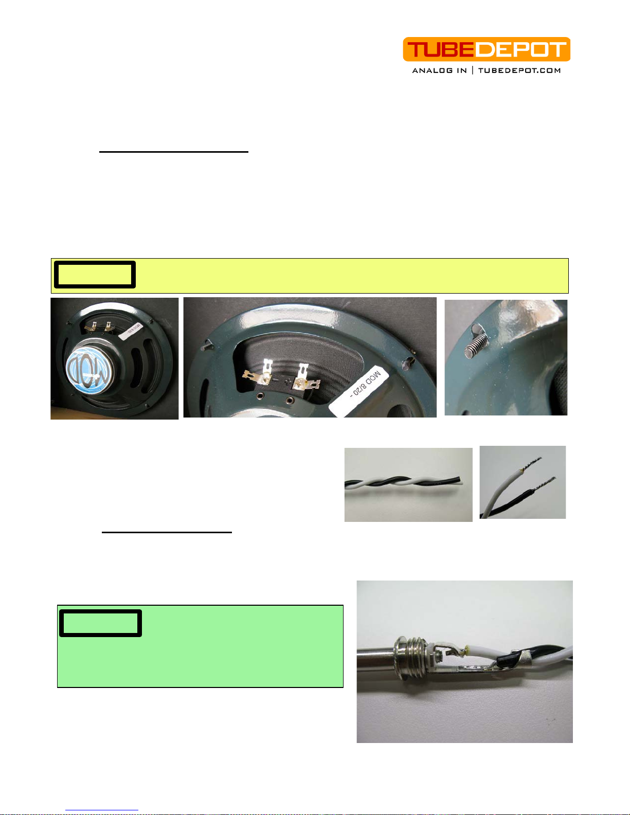
Step 1 – Remove the four nuts from the speaker mounting bolts inside the cabinet.
Step 2 – Remove the speaker from its shipping box. With speaker in hand, carefully align the
speaker mounting holes to the baffle bolts. I recommend installing the speaker with
connecting terminals on top.
Step 3 – Slowly press the speaker onto these bolts, being certain that the bolts are
proceeding through the mounting holes of the speaker equally (photos 4.2a, b, & c).
Step 4 – Once the speaker is installed on the bolts,
install and tighten the KEPS nuts.
Proceed to steps 4.3
Wiring the Speaker
Step 1 – Twist the two lengths of black and white wire together (photo 4.3a).
Step 2 – At one end, strip the insulation back ½ ” from both wires and tin these two wires
(photo 4.3b).
Step 3 – Unscrew the barrel of the ¼ ” phone plug.
Step 4 – Solder the two tinned wires to the plug; white
to center and black to shield (photo 4.3c). Reinstall
plug barrel.
Step 5 – At opposite end of the twisted wire pair, strip the insulation ¼” and tin both wires.
TubeDepot.com 7
4.4
photo 4.3e
Once the backing is removed from the aluminum tape, the tape will have a tendency to curl.
Be sure to keep the tape straight to avoid having the tape stick permanently to itself.
CAUTION
photo 4.4a
photo 4.4b
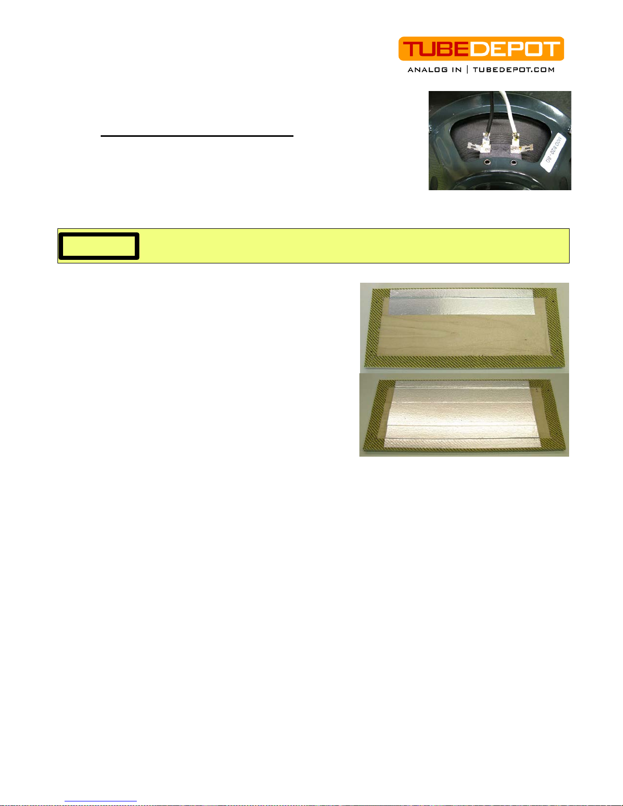
Step 6 – Solder these wires to the solder terminals of the
speaker; the white wire to the “+” terminal and the black wire to
the “-” terminal (photo 4.3e).
Proceed to 4.4
Installing the Shielding Tape
Step 1 – Place the removed back panel with the tweed side toward
the desk and the wood side facing up.
Step 2 – Cut the 30” aluminum shielding tape strip into three equal
lengths of 10”
Step 3 – Remove the backing from the first of the three shielding tape strips.
Step 4 – Apply the aluminum tape to the back of the
panel. Leave 1/8th of an inch space at the top of the
panel and centered the strip between the two panel
edges (photo 4.4a).
Step 5 – Remove the backing from the second
shielding tape strip and apply the tape to the back of
the panel similar to the first strip. Place it just below the
first strip, over lapping by 1/8th of an inch and centered
on the panel.
Step 6 – Remove the backing from the final s hi eldi ng
tape strip and apply the tape to the back of the panel
similar to the previous two strips. Align the edge of the
tape along the bottom edge of the panel, offset by 1/8th
of an inch from the bottom edge of the panel and overlapping the second strip (photo 4.4b).
Proceed to chapter 5
8 TubeDepot.com
5
Circuit Assembly
5.1
For great hints on improved soldering skills, review Appendix B at the end of this manual.
Additionally, visit:
NOTE
CAUTION
Electrolytic capacitors DO have a polarity and must be installed into the circuit according to
the markings on the component and the PC board.
NOTE
See “Cool Mods”, chapter 10 for description on how to use this
control
photo 5.1a
Here is where good soldering skills and attention to detail will pay off. By following these
directions, you should be able to complete the circuit assembly quickly and without errors.
I encourage you to first read all the steps to familiarize yourself with not only the installation
flow, but also the components to be used. Appendix A has explanations on how to read the
value codes found on both the resistors and capacitors. Appendix B has helpful hints on
improving soldering skills.
Printed Circuit Board (PCB) Assembly
This PCB was designed to sound great and to maximize your customizing ability in a
compact, easy to assemble package. This PCB layout closely follows the original point-topoint layout in order to duplicate any tone shaping created by component and wiring proximity
interactions. With over-sized traces and through-hole plating, this board will provide years of
trouble free life.
Step 1 – Gather all components necessary to complete the PCB. Separate the components
by type; the resistors in one pile, the capacitors in another, the trim pot a third. The resistors
will be installed first. They have no polarity and can therefore be installed in either direction.
Step 2 – Install a 1.5K / ½ watt resistor (brown, green, red, gold) in R6 position.
Step 3 – Install two 68K / ½ watt resistors (blue, gray, orange, gold) in positions R1 & R2.
Step 4 – Install two 100K / ½ watt resistors (brown, black, yellow, gold) in positions R4 & R5.
Step 5 – Install a 22K / ½ watt resistor (red, red, orange, gold) in position R8.
Step 6 – Install a 220K / ½ watt resistor (red, red, yellow, gold) in position R9.
Step 7 – Install a 1.5K / ½ watt resistor (brown, green, red, gold) in position R7.
Step 8 – Install a 470 / 3 watt resistor (yellow, violet, brown, gold) in position R10. The PC
board says 2 watt but I upgraded to a larger resistor.
Step 9 – Install a 22K / 1 watt resistor (red, red, orange, gold) in position R12.
Step 10 – Install a 10K / 2 watt resistor (brown, black, orange, gold) in position R11. The PC
board says 1 watt but I upgraded to a larger resistor.
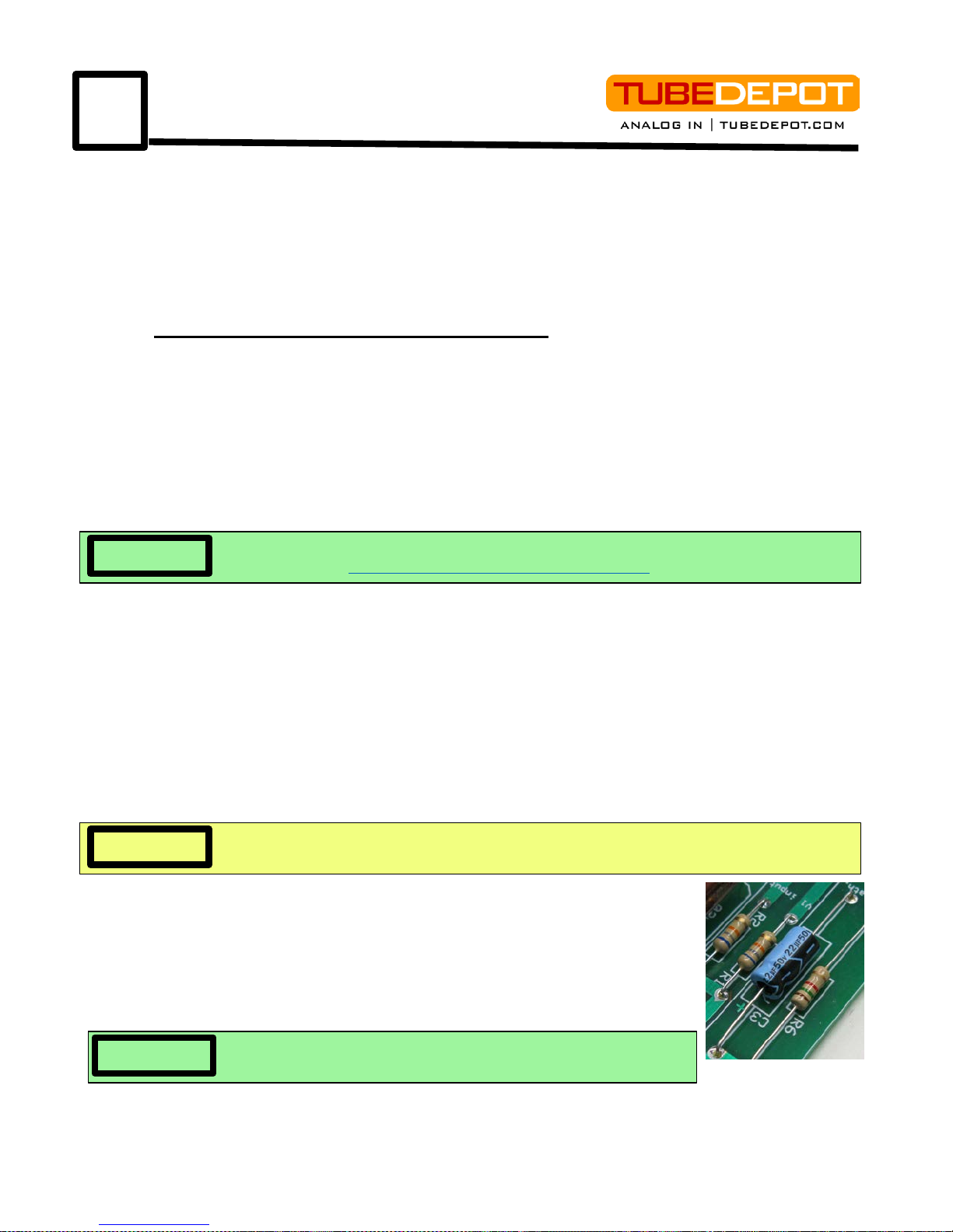
Step 11 – Install a 22ufd/50V electrolytic capacitor in position C3. This
component has a polarity, therefore it must be installed according to case
and board markings (photo 5.1a).
Step 12 – Install a 22 u fd/50V elec tr ol y t ic capac i tor in posi ti o n C4. This
component has a polarity, therefore it must be installed according to case
and board markings.
Step 13 – Install the 100K trimmer pot (VR2, negative feedback adj.)
http://www.youtube.com/user/TubeDepotTV and watch “How To Solder”.
to fine tube this amp to your sound.
 Loading...