

Page 1
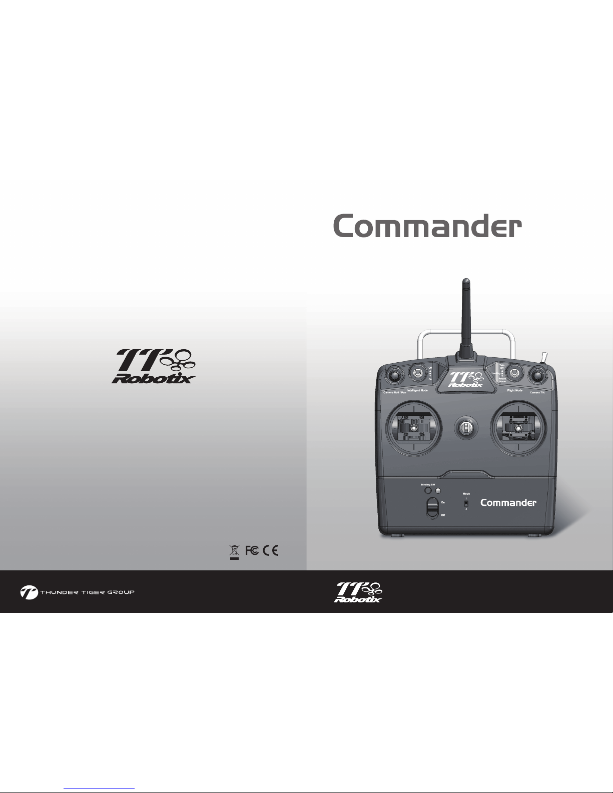
More information can view the tutorial videos on our TTR official website (www.ttrobotix.com)
or YouTube channel (https://www.youtube.com/user/ThunderTigerVideo)
您可登入TTR官網或YouTube官方頻道,以獲取最新的產品資訊與更詳盡的產品說明
thundertiger.com
JC7405
2.4
GHz DIGITAL PROPORTIONAL 9-CH RADIO CONTROL SYSTEM
Instruction Manual
No.8901
FCC ID: VEJ-COUGARGP3
Page 2
Introduction
1
Congratulations on your purchase of the Commander advanced 2.4GHz spread spectrum radio
control system. This system was specifically-designed with the latest wireless and Thunder Tiger
advanced-programming technology to meet R/C model requirements. With spread spectrum and
smart frequency-hopping system, the Commander radio system delivers precision & reliability
control without any interference risks.
Features
■
■
■
2.4GHz Frequency hopping spread spectrum wireless system
Built with advanced frequency hopping program on the spread spectrum base to deliver system
safety and reliability without interference risks.
Security ID binding link
A binding feature is included with the Commander 2.4 GHz spread spectrum system ensuring
transmitter and receiver only recognize each other to prevent interferences from other controllers.
Range checking function
A range checking button on the transmitter reduces transmitter signal for pre-flight range check.
It is recommended to perform range check before every flight.
System Contents
Specifications
Item No.
Configuration
Encoder
Frequency(GHz)
Modulation
Current Drain
Frequency Band Width
Transmission System
Antenna Type
Antenna Peak Gain
Power Requirement
Dimension (w/o antenna)
Weight (g/oz)
Commander
8901
Dual Sticks
9Ch
2.4GHz
GFSK
[email protected]
2402~2479MHz
FHSS
1/4λDipole Sleeve
2dBi Typical
7.2V/6 cell AA Battery
180 x 180 x 70mm
435g / 15.37oz
Receiver
Frequency(GHz)
BEC
Type
Antenna Type
Battery Power
Dimension(mm)
Weight(g/oz)
TRS901DD
2.4GHz
No
PPM
Dual Antenna & Diversity
4.8~7.4V
29.2 x 44.9 x 14.1
10.5g / 0.37oz
Transmitter
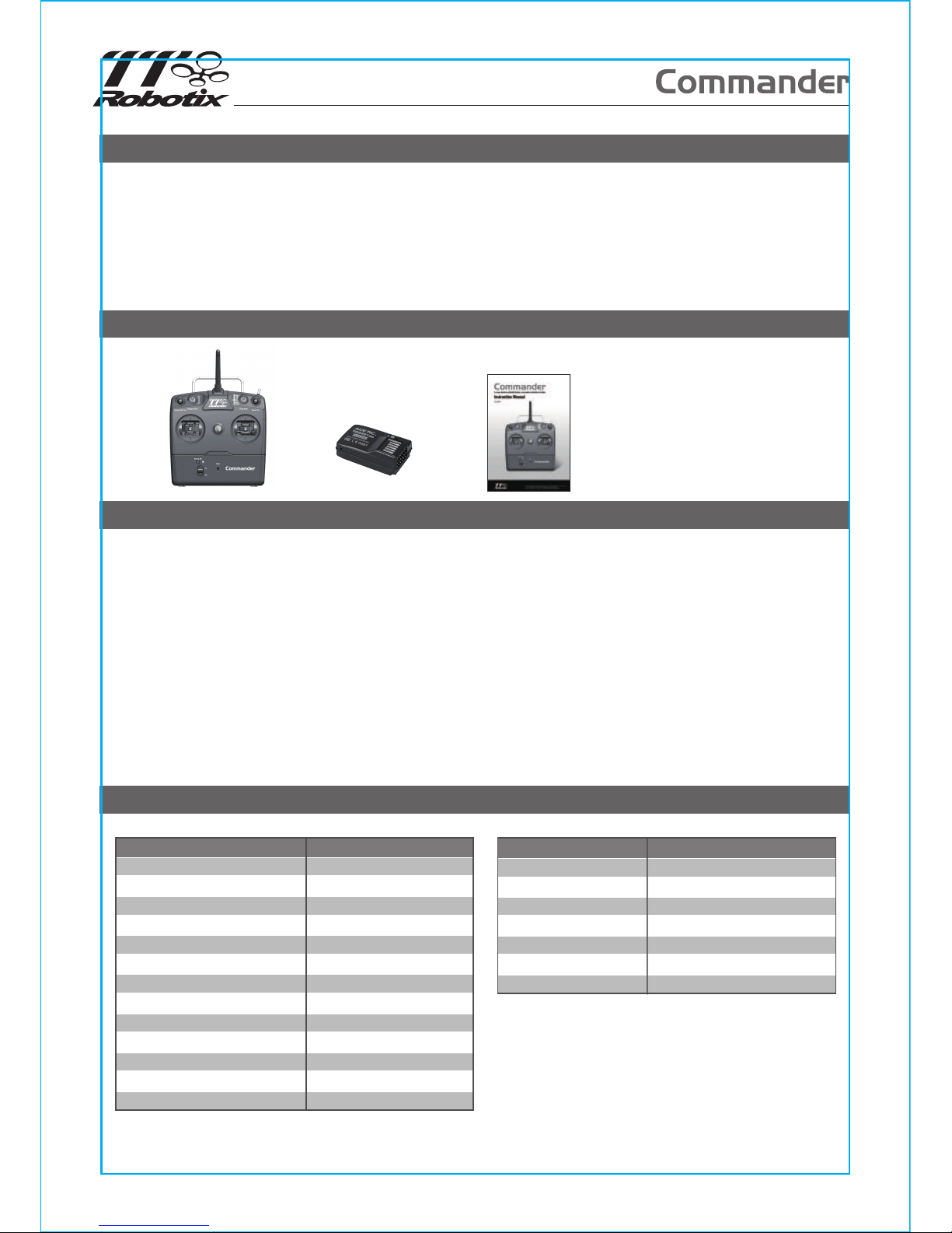
Transmitter Receiver Manual
1
Page 3
Transmitter Controls
11
1
2
4
6
8
10
7
9
5
3
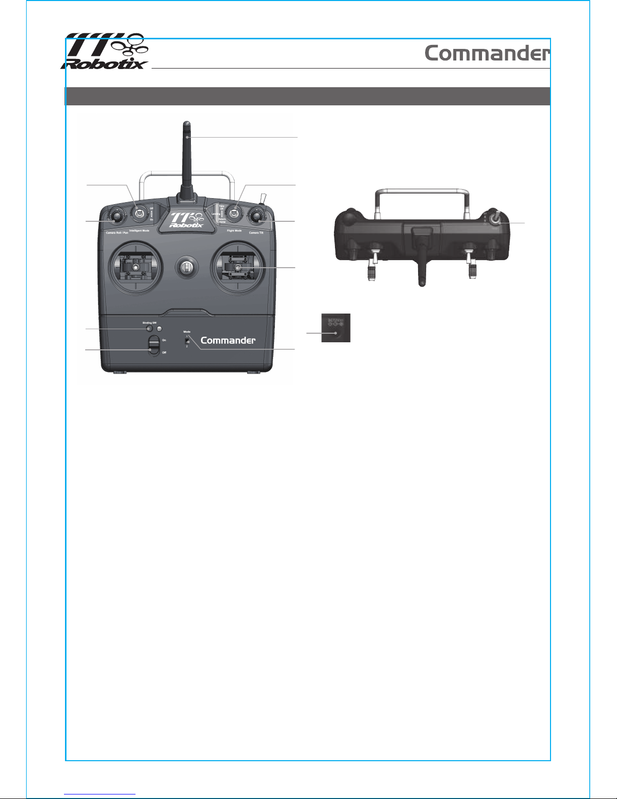
Antenna
Flight Mode Switch:
(1) Take Off Mode: When the GPS antenna receives 7 signals from the satellite, it will switch to the
GPS mode automatically.
(2) Landing Assist: The Landing Assist will automatically decelerate and stabilize the drone when in
landing, the function will be activated when drone is within 2M from the ground.
(3) Return Home: The Return Home feature will autopilot the drone back to the original take off point
and proceed the landing automatically.
IOC (Intelligent Orientation Control):
(1) IOC OFF: When IOC switches to the “OFF” mode, the IOC function will be dismissed.
(2) IOC ON: When IOC switches to the “ON” mode, the drone will be heading locked intelligently and
oriented to its original take off point
Gimbal Angle Knob(Tilt): Trim the Tilt of the Gimbal.
Gimbal Angle Knob(Roll/Pan): Trim the Roll or Pan of the Gimbal.
Joystick
Binding Button
Stick Mode Switch:
(1) MODE 1:
(1-1) Altitude Control (CH 3) is at right joystick/ Up and Down.
(1-2) Forward/Backward Control( CH 2) is at left joystick/ Up and Down.
(2) MODE 2:
(2-1) Altitude Control (CH 3) is at left joystick / Up and Down.
(2-2) Elevator Control (CH 2) is at right joystick/ Up and Down.
Power Switch
Charger Jack
Reract Landing Skid Switch: To control the Retract Landing Gear uplock / downlock.
1.
2.
3.
4.
5.
6.
7.
8.
9.
10.
11.
2
Page 4
Radio installation
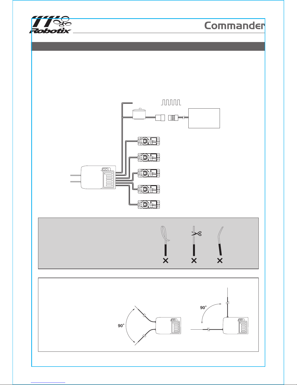
Before installing your radio into your model, connect the receiver, servos, and switch
harness/battery pack as shown. In addition to checking for proper operation, this "bench test" helps
you become familiar with the operation of your radio. Begin by turning on the transmitter, and then
turn on the receiver switch. Make sure that all servos and trims levers are operating, and take a few
moments to "play" with your system. After completion of your bench testing, turn off the receiver,
followed by the transmitter.
CAUTION
To prevent loss of radio range do not kink or
cut the gray wire, do not bend or cut the
metal tip, and do not bend or cut the white
wire at the end of the metal tip.
HELPFUL HINT
1. The two antennas must be
kept as straight as possible.
Otherwise it will reduce the
effective range.
2. The two antennas should be
placed at 90 degrees to each
other.
CH5
Switch
Harness
Receiver
Receiver
Battery
CH9
PPM SUM
CH8
CH7
CH6
3
Page 5
Functions
The Commander transmitter was specifically-designed to operate air models. Basic functions for
this transmitter are listed below.
NOTE
Binding process may take 2~4 seconds to execute. If binding fails, the LED light on the receiver will
turn red. Please turn off power and repeat the above steps from a) ~ e).
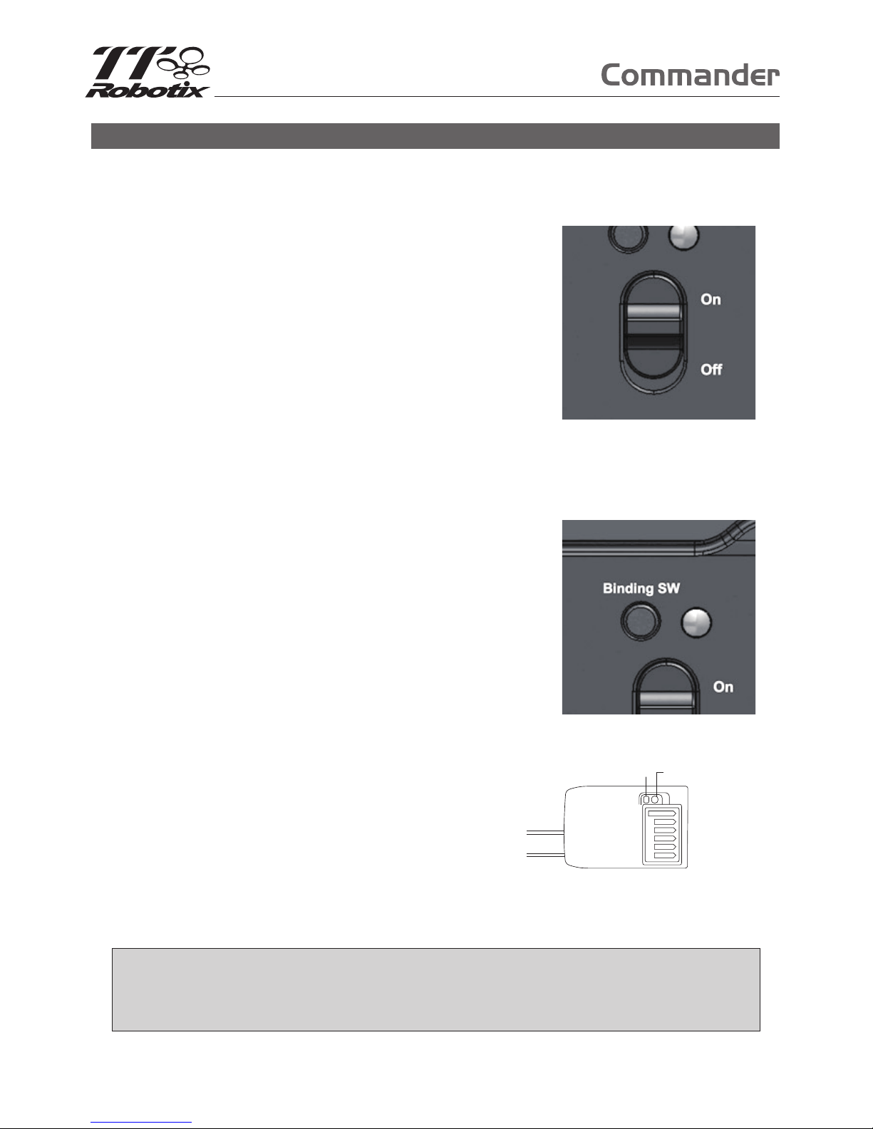
1. Power On
a) Turn On/Off
After installing the transmitter batteries, turn on the
transmitter power by sliding up the switch located on
the front middle position of the transmitter. The LED
light turns “GREEN”. To turn off the power, slide down
the switch, the LED indicator light will turn off.
b) Low Battery Power Warning
If the transmitter battery power is too low, a “Bi--Bi--”
warning tone will be emitted and the LED indicator will
flash “GREEN”. It’s very dangerous to fly the model
with low battery transmitter. Please change the
batteries immediately.
2. Binding process
A binding feature is included in the Commander 2.4 GHz
spread spectrum system to ensure the transmitter and
receiver bind properly and prevent interference from
other controllers. To bind Tx/Rx, please proceed as per
the following:
a) Press and hold “Binding SW” button located on the
transmitter.
b) Simultaneously, turn on the power.
c) Release the “Binding SW” button. The binding LED
will blink Green / Red, indicating the transmitter is
binding.
d) Press and hold the BINDING push button on the
Receiver, plug the battery power connector on the
receiver to turn power on. Then release the
BINDING button.
Press & hold Binding switch
LED
Binding Switch
Receiver
6CH
e) Successful binding is confirmed by the binding LED
changing from Green / Red to a Green flash on the
transmitter. The LED will turn green on the receiver. Upon confirmation, turn off power of
the receiver and transmitter and launch normal start-up procedures.
4
Page 6
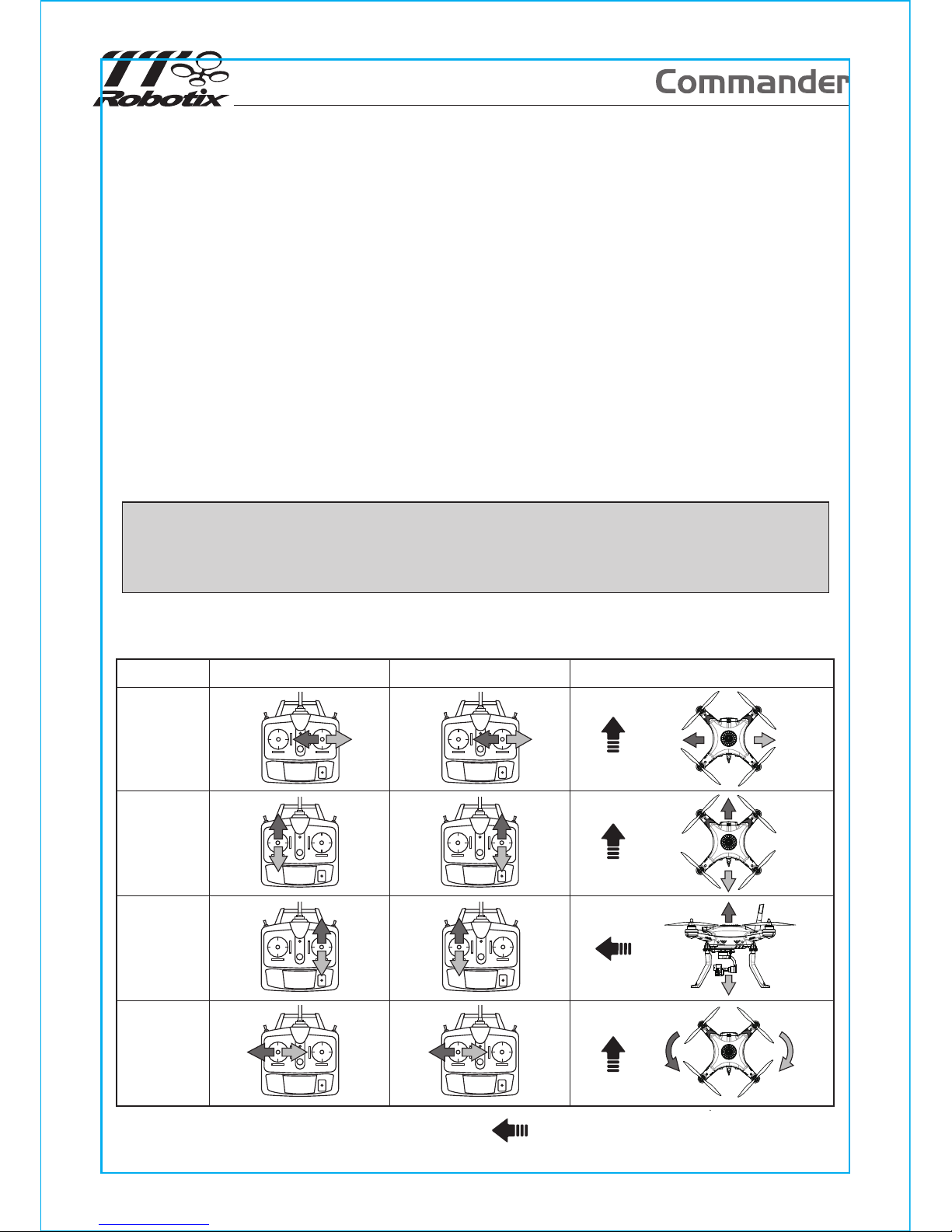
Forward Direction (Indicates Front Side)
Drone MovementMode 2Mode 1
Aileron
Elevator
Throttle
Rudder
3. Range-Check
A built-in range-check function on the transmitter reduces signal strength for pre-flight rangecheck. When this function is activated, signal strength is weak. Use the weak signal strength for
pre-flight range-check to confirm operation of wireless radio control system is normal. It is
recommended to perform a complete range-check before every flight.
NOTE
Never push the “Binding SW” button during flight. Flying under weak signal strength will result in signal
loss and model crash.
Range-Checking” procedure:
a) Turn both transmitter and model power on and ensure the system is functioning properly.
b) Take the transmitter to a distance of about 20~30m from the model.
c) Press and hold the “Binding SW” button. Signal strength is now weak. The transmitter buzzer
will signal with a “Bi - - Bi” warning tone. Please do not release “Binding SW” at this stage.
d) Operate both left and right sticks to drive movement on the servos.Visually confirm that all
movements are accurate and signal is interference-free.
e) Release “Binding SW” button. Signal reverses back to full strength and warning tone stops.
And the warning tone also will stop in the same time.
f) Model is ready to fly.
4. Stick Controls
5
Page 7
FCC Interference Statement
This equipment has been tested and found to comply with the limits for a Class B digital device,
pursuant to Part 15 of the FCC Rules. These limits are designed to provide reasonable protection
against harmful interference in a residential installation.
This equipment generates, uses and can radiate radio frequency energy and, if not installed and
used in accordance with the instructions, may cause harmful interference to radio communications.
However, there is no guarantee that interference will not occur in a particular installation. If this
equipment does cause harmful interference to radio or television reception, which can be
determined by turning the equipment off and on, the user is encouraged to try to correct the interference by one of the following measures:
■
■
■
■
Reorient or relocate the receiving antenna.
Increase the separation between the equipment and receiver.
Connect the equipment into an outlet on a circuit different from that to which the receiver is
connected.
Consult the dealer.
FCC Caution
To assure continued compliance, any changes or modifications not expressly approved by the party
responsible for compliance could void the user's authority to operate this equipment. (Example - use
only shielded interface cables when connecting to computer or peripheral devices).
This device complies with Part 15 of the FCC Rules. Operation is subject to the following two conditions:
(1) This device may not cause harmful interference, and (2) This device must accept any interference
received, including interference that may cause undesired operation.
FCC Radiation Exposure Statement
This equipment complies with FCC RF radiation exposure limits set forth for an uncontrolled
environment.This equipment should be installed and operated with a minimum distance of 20
centimeters between the radiator and your body. This transmitter must not be co-located or operating in
conjunction with any other antenna or transmitter.
The antennas used for this transmitter must be installed to provide a separation distance of at least 20
cm from all persons and must not be co-located or operating in conjunction with any other antenna or
transmitter.
Using Caution at the Flying Field
■
■
■
■
■
■
■
■
Always perform a pre-flight range-check to ensure conditions are interference-free.
Do not operate the model or use the radio in rain or lightning.
Do not operate the model or use the radio if you have been drinking alcohol or under the influence
of any other substance that could affect your skills and judgment.
Always check battery charge before flight.
Keep out of reach of children.
Do not store the radio in temperatures below -10 ˚C (14˚F) or above 40˚C (104˚F) or in a humid,
dusty, or high vibration environment.
Keep the radio away from direct sunlight.
To prevent corrosion, remove batteries before storing the radio for a long period.
5
Page 8
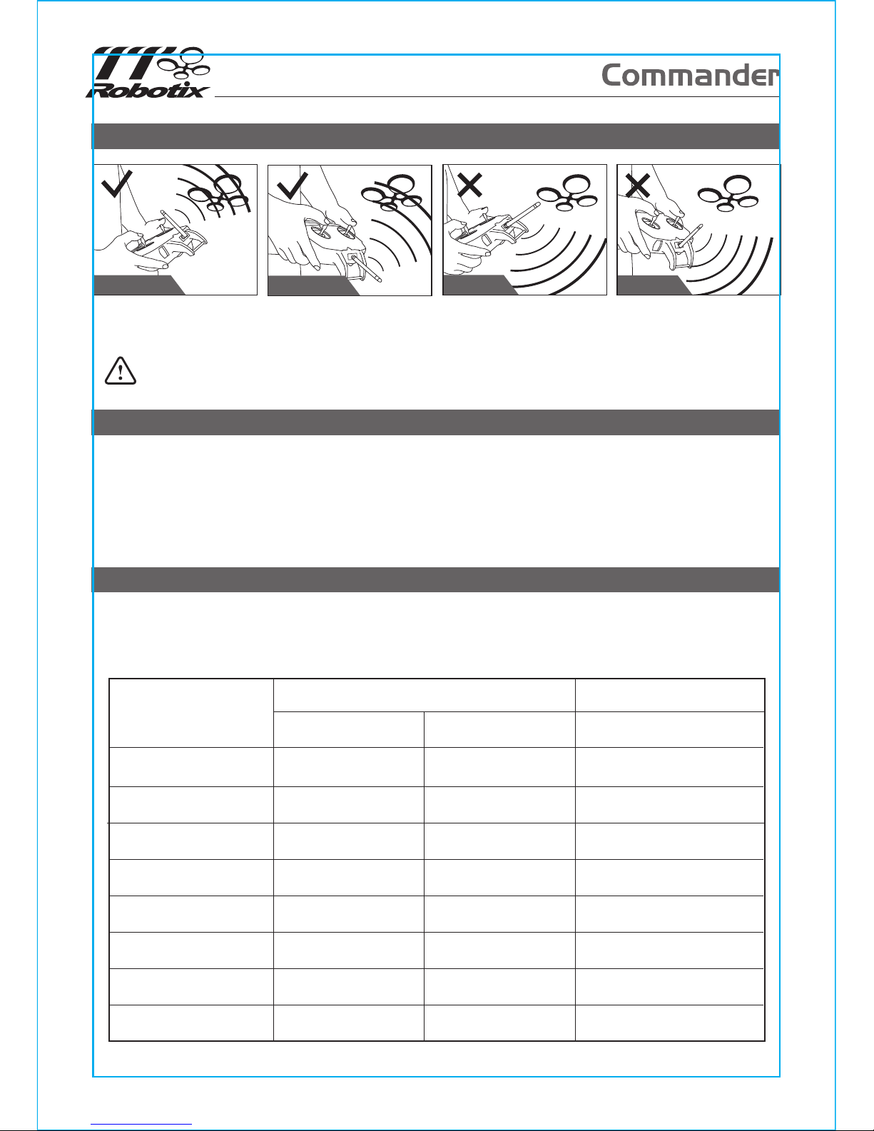
Status Indication Chart
The following chart indicates LED and buzzer status. Do not operate your model if you suspect your
radio is not working properly. If you encounter a signal not indicated on this chart and can not solve
the problems by yourself, please contact your local Thunder Tiger authorized distributor for service.
Normal Operation
Binding
Binding Success
Binding Failed
RF Failed
Range Check
Low Battery
Status
Transmitter Receiver
LED indication
Buzzer
Bi-Bi-Bi
-
-
-
-
--
Bi - - Bi
Bi - - Bi
Binding LED
Red/ 1 second
Green/ Flashing
Green/ Red Flash
Green/ Flashing
Green/ Red Flash
Red
Green/ Rapid Flashing
Green/ Flashing
Red/ 1 second
Green/ Solid
Green/ Red Flash
Green/Solid
Green/ Red Flash
Red/ Solid
Green/ Solid
Green/ Solid
Initializing
(when power on)
Additional Note for 2.4GHz Radio System
Warning! Operating range may be significantly reduced with the transmitter antenna pointing
directly at the model!
CORRECT
WRONG
CORRECT
CORRECT
WRONG
For best operating range, always ensure the largest section of your transmitter antenna faces the
model.
Service
Thank you for purchasing the ACE RC Commander Radio. This radio was produced by Thunder
Tiger Corp.
Thunder Tiger products are sold worldwide through authorized distributors supported directly by
Thunder Tiger. To receive the latest product information and enjoy full technical support, please
contact your nearest hobby shop or Thunder Tiger authorized distributor.
7
Page 9
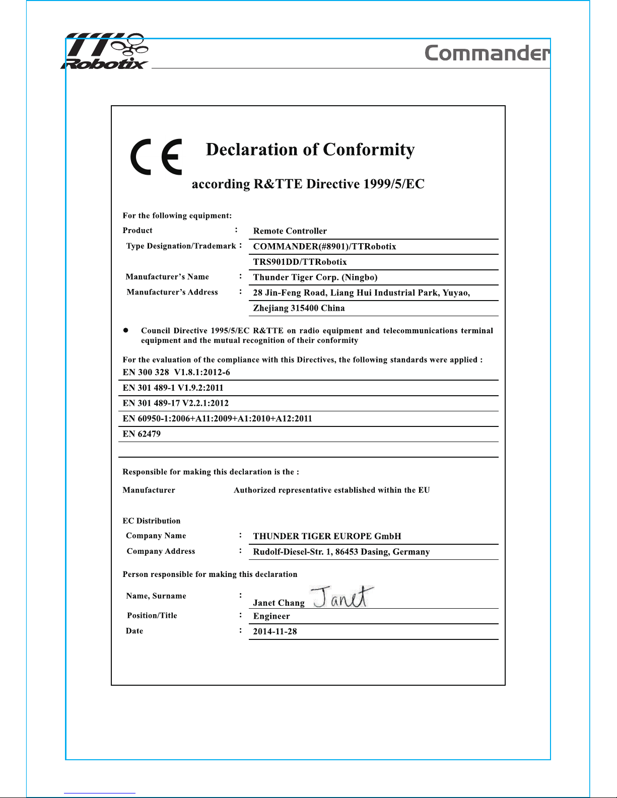
8
Page 10

Federal Communication Commission Interference Statement
This equipment has been tested and found to comply with the limits for a Class B
digital device, pursuant to Part 15 of the FCC Rules. These limits are designed to
provide reasonable protection against harmful interference in a residential installation.
This equipment generates, uses and can radiate radio frequency energy and, if not
installed and used in accordance with the instructions, may cause harmful interference
to radio communications. However, there is no guarantee that interference will not
occur in a particular installation. If this equipment does cause harmful interference to
radio or television reception, which can be determined by turning the equipment off
and on, the user is encouraged to try to correct the interference by one of the
following measures:
. Reorient or relocate the receiving antenna.
. Increase the separation between the equipment and receiver.
. Connect the equipment into an outlet on a circuit different from that to which the
receiver is connected.
. Consult the dealer or an experienced radio/TV technician for help.
FCC Caution: To assure continued compliance, any changes or modifications not
expressly approved by the party responsible for compliance could void the user's
authority to operate this equipment. (Example - use only shielded interface cables
when connecting to computer or peripheral devices).
FCC Radiation Exposure Statement
This equipment complies with FCC RF radiation exposure limits set forth for an
uncontrolled environment. This equipment should be installed and operated with a
minimum distance of 1 centimeters between the radiator and your body.
This transmitter must not be co-located or operating in conjunction with any other
antenna or transmitter.
The antennas used for this transmitter must be installed to provide a separation
distance of at least 1 cm from all persons and must not be co-located or operating in
conjunction with any other antenna or transmitter.
This device complies with Part 15 of the FCC Rules. Operation is subject to the
following two conditions:
(1) This device may not cause harmful interference, and (2) This device must accept
any interference received, including interference that may cause undesired operation
 Loading...